


 本文详细介绍了在LTE-FDD移动通信系统中,如何设计和仿真基于OFDM的下行无线传输链路,包括子载波选择、循环前缀、导频信号配置、功率控制和调制方式,以及如何通过仿真评估性能。
✅作者简介:热爱科研的Matlab仿真开发者,修心和技术同步精进,代码获取、论文复现及科研仿真合作可私信。
🍎个人主页:Matlab科研工作室
🍊个人信条:格物致知。
🔥 内容介绍
OFDM(正交频分复用)是一种在无线通信系统中广泛使用的调制技术,它能够有效地提高频谱利用率和抗多径干扰能力。LTE-FDD(长期演进-频分双工)是一种主流的移动通信标准,其下行链路采用了OFDM技术。本文将重点讨论基于LTE-FDD的OFDM下行无线传输链路设计与仿真。
首先,我们需要了解LTE-FDD的基本特点和无线传输链路结构。LTE-FDD采用了频分双工技术,即将上行和下行信号分配到不同的频段中进行传输,从而避免了上下行信号之间的干扰。在下行链路中,OFDM技术被用于将数据信号分割成多个子载波进行传输,以提高频谱利用率和抗多径干扰能力。
接下来,我们将介绍OFDM下行无线传输链路的设计要点。首先是子载波数量的确定,一般情况下会根据带宽和系统要求来确定子载波的数量。然后是循环前缀的添加,循环前缀是为了抵消多径传输引起的符号间干扰,其长度一般为符号长度的1/4。接着是导频信号的插入,导频信号用于信道估计和均衡,其位置和数量需要根据系统的要求来确定。最后是功率控制和调制方式的选择,这些都是影响系统性能的重要因素。
在设计完成后,我们可以利用仿真工具对OFDM下行无线传输链路进行仿真。仿真可以帮助我们验证设计的正确性和性能,同时也可以用于系统参数的优化和性能分析。在仿真过程中,我们需要考虑信道模型、多径干扰、噪声等因素对系统性能的影响,以及系统参数的选择对性能的影响。
总的来说,基于LTE-FDD的OFDM下行无线传输链路设计与仿真是一个复杂而又重要的课题。通过深入了解LTE-FDD和OFDM技术,合理设计无线传输链路,并利用仿真工具进行验证和分析,我们可以更好地理解系统的性能特点,从而为实际系统的部署和优化提供参考。希望本文能够对相关领域的研究和工程实践有所帮助。
📣 部分代码
% Script for MIMO LTE (mode 3)%% 开环空分复用,2个码字,2*2天线% QPSK,信道11,相关性lowclear allclear functionsdisp('Simulating the LTE Mode 3: Multiple Tx & Rx antrennas with open loop Spatial Multiplexing');%% initializationSNR_Vector = 2:2:20;BER_DLSCH_Vector = zeros(size(SNR_Vector)); % 传输层的BER (其实传输层用TrCh表示)BER_Physical_Vector = zeros(size(SNR_Vector)); % 物理层的BERnum_initialData = [7480,7736,7864,15264,15648,15840,22920,23432,23688]; % 这是自己算的对应每种调制方式的最开始的生成随机数据的大小,7480,7736,7864对应QPSK的第0、第5及其他子帧生成随机数据的大小,15264,15648,15840对应16QAM的第0、第5及其他子帧生成随机数据的大小,22920,23432,23688对应64QAM的第0、第5及其他子帧生成随机数据的大小% LTE_params = LTE_parameters( num_initialData,chanBandWidth,cpType,maxIter,PDSCH_Qm,NumTx,NumRx, NumLayer,NumCodeword,channelType,SNR,CorrelationLevel)LTE_params = LTE_parameters( 0,6,1,6,1,2,2, 2,2,11,0,1); % num_initialData和SNR还没有赋正确值switch LTE_params.PDSCH_Qmcase 1Modulation_Type = 'QPSK';case 2Modulation_Type = '16QAM';case 3Modulation_Type = '64QAM';endswitch LTE_params.channel_typecase 1channel_type = 'awgn channel model, fixed channel matrix';case 2channel_type = 'awgn model,random channel matrix';case 3channel_type = 'SCM';case 4channel_type = 'flat-low-mobility ';case 5channel_type = 'flat-high-mobility';case 6channel_type = 'frequency-selective-low-mobility';case 7channel_type = '% frequency-selective-high-mobility';case 8channel_type = 'EPA 0Hz';case 9channel_type = 'EPA 5Hz';case 10channel_type = 'EVA 5Hz';case 11channel_type = 'EVA 70Hz';case 12channel_type = 'ETU 70Hz';case 13channel_type = 'ETU 300Hz';case 14channel_type = 'for test';endfprintf(1,'Modulation Type: %s, channel model: %s\n',Modulation_Type,channel_type);%% Simulation looptic;for idx = 1:length(SNR_Vector)LTE_params.channel_SNR = SNR_Vector(idx);maxNumErrs=1e5;maxNumBits=1e6;Measures_TrCh = zeros(3,1); %initialize BER output for TrCh layerMeasures_Phy = zeros(3,1); %initialize BER output for Physical layerBer_TrCh = comm.ErrorRate;Ber_Phy = comm.ErrorRate;% Rx_data1 = []; % 均衡后没有解调的数据,用于画星座图% Rx_data2 = []; % 均衡后没有解调的数据,用于画星座图nS = 0;while (( Measures_TrCh(2)< maxNumErrs) && (Measures_TrCh(3) < maxNumBits))if(nS==0)LTE_params.DLSCH_dataGenerator = num_initialData(1);elseif(nS == 10)LTE_params.DLSCH_dataGenerator = num_initialData(2);elseLTE_params.DLSCH_dataGenerator = num_initialData(3);endend[ Tx_a1,Tx_a2,Rx_a1,Rx_a2,Tx_f1,Tx_f2,Rx_f1_hard,Rx_f2_hard,Tx_g1,Tx_g2,Rx_g1_hard,Rx_g2_hard,Rx_data_estimate,nVar,iters1,iters2] = LTE_openLoop_step( LTE_params,nS,LTE_params.channel_SNR);% 记录Rx_data的值,用于画星座图% Rx_data1 = [Rx_data1;Rx_data_estimate{1}];% Rx_data2 = [Rx_data2;Rx_data_estimate{2}];% Calculate bit errors% TrChdataIn_TrCh = [Tx_a1.',Tx_a2.'].';dataOut_TrCh = [Rx_a1.',Rx_a2.'].';% PhysicaldataIn_Phy = [Tx_f1.',Tx_f2.'].';dataIn_Phy = logical(dataIn_Phy); % 因为调用comm.ErrorRate需要logicaldataOut_Phy = [Rx_f1_hard.',Rx_f2_hard.'].';Measures_TrCh = step(Ber_TrCh, dataIn_TrCh, dataOut_TrCh);Measures_Phy = step(Ber_Phy, dataIn_Phy, dataOut_Phy);fprintf(1,'TrCh: Bits processed %8d ; Errors found %5d BER = %g \r', Measures_TrCh(3), Measures_TrCh(2), Measures_TrCh(1));fprintf(1,'Physical: Bits processed %8d ; Errors found %5d BER = %g \r', Measures_Phy(3), Measures_Phy(2), Measures_Phy(1));% Update subframe numbernS = nS + 2;if nS > 19,nS = mod(nS, 20);end;endBER_DLSCH_Vector(idx) = Measures_TrCh(1); % 传输层的BER (其实传输层用TrCh表示)BER_Physical_Vector(idx) = Measures_Phy(1); % 物理层的BERdisp('TrCh BER:');disp(BER_DLSCH_Vector);disp('Physical BER:');disp(BER_Physical_Vector);endtoc;% 确定title和legend的值Title1 = ['BER-SNR of TM3, ',Modulation_Type,', ',channel_type,', ',LTE_params.channel_MIMOChannel_CorrelationLevel];Title2 = ['Physical layer BER-SNR of TM3, ',Modulation_Type,', ',channel_type,', ',LTE_params.channel_MIMOChannel_CorrelationLevel];Legend = [Modulation_Type,' ,20MHz BW'];temp_idx = find(BER_DLSCH_Vector==0);temp = BER_DLSCH_Vector;temp(temp_idx) = 1e-8;FileName = ['TM3_',Modulation_Type,'_',channel_type,'_',LTE_params.channel_MIMOChannel_CorrelationLevel];save(FileName);figure(1);semilogy(SNR_Vector, temp);title(Title1);legend(Legend);xlabel('SNR (dB)');ylabel('BER');grid;figure(2);semilogy(SNR_Vector, BER_Physical_Vector);title(Title2);legend(Legend);xlabel('SNR (dB)');ylabel('BER');grid;FigureName1 = [Modulation_Type,'_',channel_type,'_',LTE_params.channel_MIMOChannel_CorrelationLevel,'_TrCh_TM3.jpg'];FigureName2 = [Modulation_Type,'_',channel_type,'_',LTE_params.channel_MIMOChannel_CorrelationLevel,'_Phy_TM3.jpg'];saveas(figure(1),FigureName1);saveas(figure(2),FigureName2);
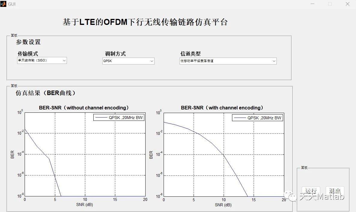
⛳️ 运行结果
🔗 参考文献
[1] 吴秋景.基于picoChip PC203的LTE系统基站物理层API的设计与实现[D].北京邮电大学[2023-12-28].DOI:CNKI:CDMD:2.2010.222179.
[2] 向伟.3GPP LTE下行链路物理层研究与实现[D].电子科技大学,2011.DOI:CNKI:CDMD:2.1011.191936.
[3] 刘宏轩.LTE-TDD下行波束成形技术研究[D].电子科技大学[2023-12-28].DOI:CNKI:CDMD:2.1011.073556.
[4] 余治良.LTE-Advanced系统下行链路同步技术的仿真和实现[D].电子科技大学[2023-12-28].DOI:10.7666/d.D662961.


 2689
2689

 被折叠的 条评论
为什么被折叠?
被折叠的 条评论
为什么被折叠?
 到【灌水乐园】发言


