


 本文探讨了智能反射表面(IRS)在无线通信中的应用,强调了准确获取信道状态信息(CSI)的重要性以及由此带来的挑战。在窄带系统中,IRS引入了大量的信道系数,且由于没有射频链路,无法直接进行信道估计。为解决此问题,提出了半被动IRS的概念,通过集成传感器进行信道感应和反射模式的交替操作来估算信道。然而,这带来了低维到高维信道重建的难题和精度限制。文章还讨论了增加传感器数量、提高ADC分辨率和延长信道感应时间作为改善信道估计的方法。对于被动IRS,通过BS和用户在上行/下行链路中估计级联信道。主要挑战包括联合设计、反射模式选择和接收信号处理。
A. Problem Description and Challenges
To fully achieve various performance gains brought by IRS, ths acquisition of accurate Channel State Informance (CSI) is crucial, which, however, is practically challenging.
Next, we consider a general problem as follows. Specifically, assuming the IRS-aided uplink multi-user MIMO communication in a narrow-band system over flat-fading channels, the received signal at the MBM_BMB-antenna BS from KKK users (each of which is equipped with MuM_uMu antennas) can be expressed as
y=∑k=1K(GTΘHr,k+Hd,k)xk+z(52)
\bf{y}=\sum_{k=1}^{K} \left( \bf{G}^{T} \bf{\Theta} \bf{H}_{r, k}+\bf{H}_{d, k} \right) \bf{x}_{k} + \boldsymbol{z} \qquad(52)
y=k=1∑K(GTΘHr,k+Hd,k)xk+z(52)
其中,G∈CN×MB\mathbf{G} \in \mathbb{C}^{N \times M_B}G∈CN×MB, Hr,k∈CN×Mu\mathbf{H}_{r, k} \in \mathbb{C}^{N \times M_u}Hr,k∈CN×Mu, and Hd,k∈CMB×Mu\mathbf{H}_{d, k} \in \mathbb{C}^{M_B \times M_u}Hd,k∈CMB×Mu denote IRS-BS, user k−IRSk-IRSk−IRS, and user kkk-BS direct channels, respecitvely, with k=1,...,Kk=1,...,Kk=1,...,K; Θ=diag(ejθ1,ejθ2,...,ejθN)\mathbf{\Theta} = \text{diag}(e^{j\theta_1},e^{j\theta_2},...,e^{j\theta_N})Θ=diag(ejθ1,ejθ2,...,ejθN) represents the diagonal phase-shift matrix of one or more IRSs comprising NNN relfecting elements in total, with the reflection amplitude of each element set to one for simplicity; xk∈CMu×1\mathbf{x}_k \in \mathbb{C}^{M_u \times 1}xk∈CMu×1 is the transmit signal of user kkk; and z∈CMB×1\mathbf{z} \in \mathbb{C}^{M_B \times 1}z∈CMB×1 is the Addictive White Gaussian Noise (AWGN).
Accordingly, the uplink CSI includes G\mathbf{G}G, {Hr,k}k=1K\{\mathbf{H}_{r,k}\}^{K}_{k=1}{Hr,k}k=1K, and thus the total number of uplink channel coefficients consists of two parts:
- The number of channel coefficients (K×NMu+MBNK \times N M_u + M_B NK×NMu+MBN) for the links to/from the (equivalent single) IRS (i.e., G\mathbf{G}G and {Hr,k}k=1K\{\mathbf{H}_{r,k}\}^{K}_{k=1}{Hr,k}k=1K), which are newly introduced due to the employment of IRS;
- The number of channel coeeficients (equal to K×MBMuK \times M_B M_uK×MBMu) for the direct links (i.e., {Hd,k}k=1K\{\mathbf{H}_{d,k}\}^{K}_{k=1}{Hd,k}k=1K), which exist in conventional communication systems without IRS.
The Diferences of the total number of channel coefficients between Time-Division Duplexing (TDD) and Frequency-Division Duplexing (FDD) systems.
- FDD: the FDD system requires to estimate twice the number of channel coefficients in (52) due to the generally non-symmetric uplink and downlink channels;
- TDD: the TDD system may only need to acquire either the uplink or downlink channel coefficients by exploiting the uplink-downlink channel reciprocity.
Challenging:
- A large number of channel coefficients: In broad-band communication systems over frequency-selective fading channels, more channel coefficients are induced for both user-BS direct channels and user-IRS-BS reflected channels due to (1) multi-path delay spread and (2) resultant convolutionof time-domain impluse responses of user-IRS and IRS-BS multi-path channels , which makes the channel acquisition problem even more challenging.
- No RF chains: Reflecting elements, which donot possess any active RF chains, cannot transmit pilot/training signals to facilitate channel estimation, which is different to the active BSs/user terminals in conventional wireless systems.
B. Semi-Passive IRS Channel Estimation
To endow the IRS with sensing capability for channel estimation, additional sensing devices (such as low-power sensors) need to be integrated into IRS, each equipped with a low-cost receive RF chain (e.g, low-resolution Analog-to-Digital Converter (ADC) ) for processing the sensed signal.
(1). Two IRS Modes in Semi-Passive IRS Channel Estimation
As such, the semi-passive IRS generally operates in one of the following two modes alternately over time:
- Channel sensing mode: With all the reflecting elements turned OFF, the sensors are actived/enabled to receive the pilot signals from the BS/users in the downlink/uplink for estimating their respective channels to IRS.
- Reflection mode: With the sensors deactived/disabled, the IRS reflecting elements are turned ON to reflect the data signals from the BS/users for enhancing the downlink/uplink communication, respectively.
(2). Estimation Phases of Semi-Passive IRS
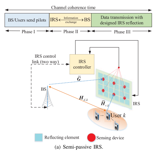
As shown in the above figure, a general transmission protocol for semi-passive IRS can be divided into three phases.
- In the first phase, the BS/users send their pilot/training signals in the downlink/uplink to estimate the BS-user direct channels as in the conventional system, while the IRS enables channel sensing mode to estimate the Channel State Information (CSI) from the BS/users based on the signals received by its sensors.
- In the second phase, the CSI is exchanged between the IRS controller and BS, based on which the active and passive beamforming coefficients are jointly designed at the IRS controller or BS, and then sent to the other via the separate wired/wireless backhaul link between them.
- In the third phase, the IRS switches to the relection mode to assist data transmission between the BS and users with the designed active/passive beamforming coefficients set at the BS/IRS.
To be noted, only the downlink CSI of BS →\rightarrow→ IRS links and uplink CSI of users →\rightarrow→ IRS links can be separately estimated by the IRS sensors; whereas that of their corresponding reverse links can be obtained only in the TDD system by leveraging the channel reciprocity. However, such CSI is unavailable in the FDD system, thus making channel estimation in FDD systems infeasible for semi-passive IRS.
(3). Challeges in Semi-Passive IRS Estimation
As shown in the above figure, Gˉ∈CNs×MB\bar{G} \in \mathbb{C}^{N_s \times M_B}Gˉ∈CNs×MB and Hˉr,k∈CNs×MB\bar{H}_{r,k} \in \mathbb{C}^{N_s \times M_B}Hˉr,k∈CNs×MB denote the channels from the BS and user kkk to the NsN_sNs IRS sensors, respectively.
- The essential challenge for semi-passive IRS channel estimation is how to construct the high-dimensional channels G\mathbf{G}G and Hr,k\mathbf{H}_{r,k}Hr,k from the estimated CSI on the low-dimensional channel Gˉ\mathbf{\bar{G}}Gˉ and Hˉr,k\mathbf{\bar{H}}_{r,k}Hˉr,k. This is because the dimension of Gˉ∈CNs×MB\bar{G} \in \mathbb{C}^{N_s \times M_B}Gˉ∈CNs×MB/Hˉr,k∈CNs×MB\bar{H}_{r,k} \in \mathbb{C}^{N_s \times M_B}Hˉr,k∈CNs×MB is lower than that of G∈CN×MB\mathbf{G} \in \mathbb{C}^{N \times M_B}G∈CN×MB/Hr,k∈CN×Mu\mathbf{H}_{r, k} \in \mathbb{C}^{N \times M_u}Hr,k∈CN×Mu in (52)(52)(52).
- The channel estimation accuracy for semi-passive IRS is generally limited by (1) the number of sensors, (2) ADC resolution, and (3) the channel sensing (downlink/uplink training) time.
(4). Improvement Methods for Semi-Passive IRS Channel Estimation
- Increasing the number of sensors: it provides more measurements for reducing the IRS CSI construction error in general;
- Higher-resolution ADC: it can reduce quantization error;
- Increasing the channel sensing time: it can average out the sensing noise more effectively.
(5). Some Key Points
- Fixed locations: Since the AP and IRS are at fixed locations once deployed, the AP-IRS link typically has a much longer channel coherence time than the IRS-user link (due to user mobility) and thus can be considered as quasi-static.
- As the AP and IRS are typically at high altitudes with few scatterers between them, the AP-IRS link can be efficiently estimated by exploiting some channel properites, such as, low-rank, sparsity, spatial correlation, etc. As a result, it is less challeging to acquire the CSI of the AP-IRS link, as compared to that of the IRS-user link.
Future Works
C. Passive IRS Channel Estimation
To be noted, the IRS without sensors cannot acquire the CSI between IRS and BS/user directly, but it provides a approach to estimate the cascaded user-IRS-BS channels at the BS/users in the uplink/downlink, respectively.
And, this approach, unlike the case of semi-passtive IRS, can apply to both TDD and FDD systems and only needs to estimate the cascaded channel thanks to the uplink-downlink channel reciprocity.
The total number of channel coefficients for the cascaded user-IRS-BS links is K×NMBMuK \times N M_B M_uK×NMBMu which is in general much larger than that of channel coefficients for the separate user-IRS and IRS-BS links (equal to K×NMu+MBNK \times N M_u + M_B NK×NMu+MBN).
(1). Estimation Phases of Passive IRS Channel Estimation
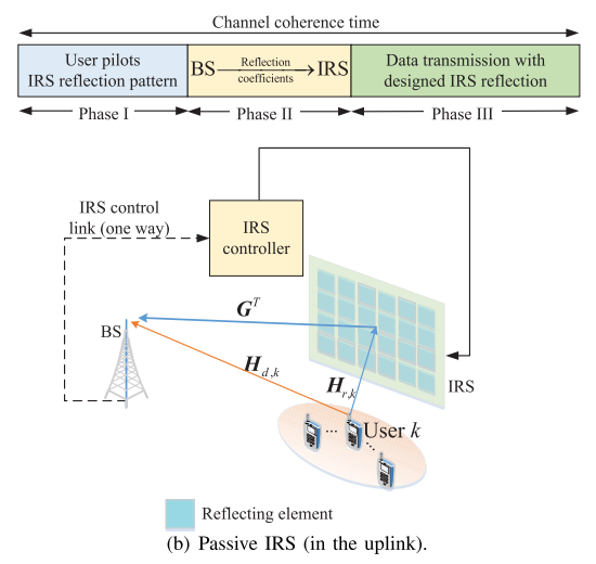
- IRS sets to reflection pattern for user pilots: In the first phase, users transmit orthogonal pilots to the BS and meanwhile the IRS varies its reflection coefficients according to a pre-designed reflection pattern, based on which the BS estimates both the user-BS direct channels and the cascaded user-IRS-BS channels.
- BS&BS jointly allocate beamforming coefficients: In the second phase, the CSI is exchanged between the IRS controller and BS, based on which the active and passive beamforming coefficients are jointly designed at the IRS controller or BS and then sent to the other via the separate wired/wireless backhual link between them.
- Data transmission with designed IRS relfection: In the third phase, the IRS controller sets the relection coefficients accordingly for assisting independent data transmission from the users to BS.
To be noted, for TDD system, the estimated uplink CSI can also be used to design IRS relfection for data transmissions in the downlink from the BS to users; while for FDD system, the transmission protocol in the above figure is still applicable for the downlink, with the only modification that the roles of the BS and users are swapped in the first phase, i.e., the BS-user/BS-IRS-user channels are estimated at the users based on the pilot signals sent by the BS, then the users need to feed back their estimated CSI to the BS for the joint optimization of IRS reflection and BS transmit beamforming.
(2). Challenges
For the (uplink) passive IRS channel estimation, the key problems are
1) the joint design of the pilot sequences,
2) IRS reflection, and
3) signal processing algorithm at the receiver to accurately estimate the channels with minimum training overhead (number of pilot symbols).


 786
786

 被折叠的 条评论
为什么被折叠?
被折叠的 条评论
为什么被折叠?
 到【灌水乐园】发言


