


 本文档详细介绍了如何配置MSTP生成树,包括基础的链路配置、链路聚合、MSTP区域配置、根桥选举,以及VRRP负载均衡设置,以确保网络的稳定性和高可用性。通过配置VRRP虚拟IP地址,实现网关冗余,提升网络服务的可靠性。
实验topo
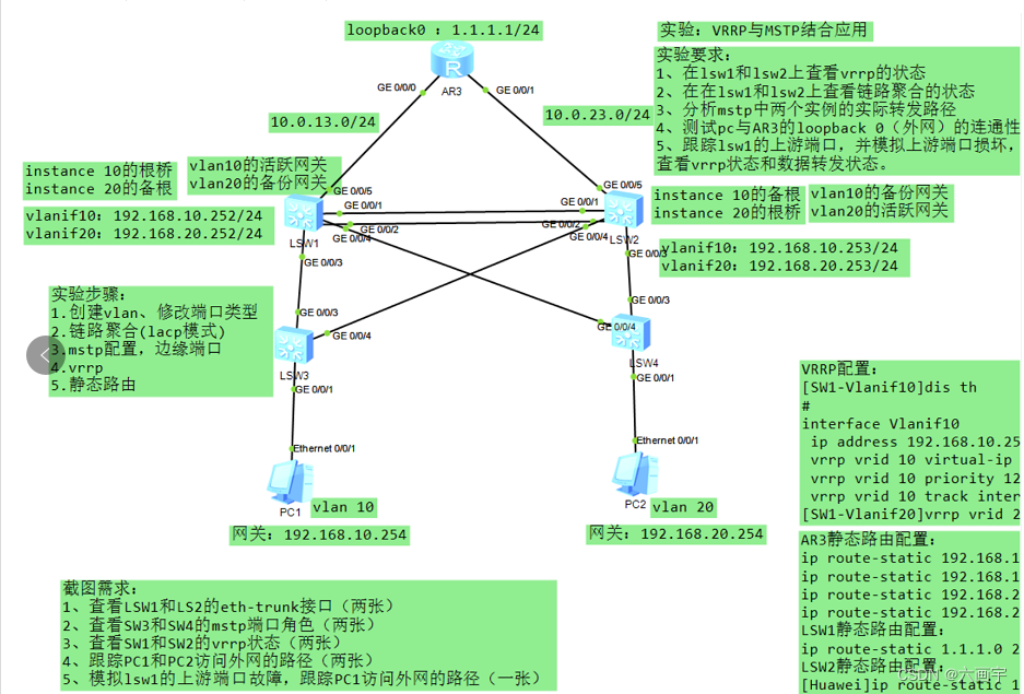
将各设备进行基础配置
1.创建vlan、修改端口类型
将交换机之间连接的接口配置为trunk口并放行,将交换机连接PC的接口配置为access口
SW1
interface GigabitEthernet0/0/3
port link-type trunk
port trunk allow-pass vlan 2 to 4094
#
interface GigabitEthernet0/0/4
port link-type trunk
port trunk allow-pass vlan 2 to 4094
#
interface GigabitEthernet0/0/5
port link-type access
port default vlan 30
SW2
interface GigabitEthernet0/0/3
port link-type trunk
port trunk allow-pass vlan 2 to 4094
#
interface GigabitEthernet0/0/4
port link-type trunk
port trunk allow-pass vlan 2 to 4094
#
interface GigabitEthernet0/0/5
port link-type access
port default vlan 40
SW3
interface GigabitEthernet0/0/3
port link-type trunk
port trunk allow-pass vlan 2 to 4094
#
interface GigabitEthernet0/0/4
port link-type trunk
port trunk allow-pass vlan 2 to 4094
interface GigabitEthernet0/0/1
port link-type access
port default vlan 10
SW4
interface GigabitEthernet0/0/3
port link-type trunk
port trunk allow-pass vlan 2 to 4094
#
interface GigabitEthernet0/0/4
port link-type trunk
port trunk allow-pass vlan 2 to 4094
interface GigabitEthernet0/0/1
port link-type access
port default vlan 20
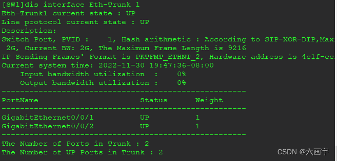
2.创建链路聚合
SW1
interface GigabitEthernet0/0/1
eth-trunk 1
#
interface GigabitEthernet0/0/2
eth-trunk 1
interface Eth-Trunk1
port link-type trunk
port trunk allow-pass vlan 2 to 4094
mode lacp-static
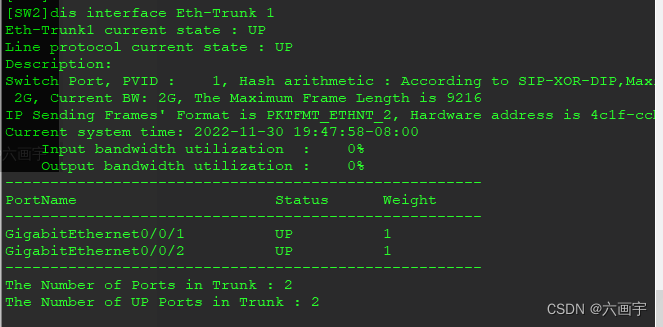
SW2
interface GigabitEthernet0/0/1
eth-trunk 1
#
interface GigabitEthernet0/0/2
eth-trunk 1
interface Eth-Trunk1
port link-type trunk
port trunk allow-pass vlan 2 to 4094
mode lacp-static
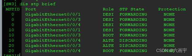
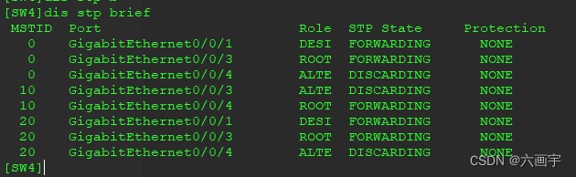
3.mstp配置,端口配置
sw1到sw4配置
stp region-configuration
region-name huawei
instance 10 vlan 10
instance 20 vlan 20
active region-configuration
#
mstp根桥配置
SW1
stp instance 10 root primary
stp instance 20 root secondary
SW2
stp instance 10 root secondary
stp instance 20 root primary
sw3到sw4配置边缘端口
interface GigabitEthernet0/0/1
stp edged-port enable
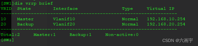
4.vrrp配置
SW1
interface Vlanif10
ip address 192.168.10.252 255.255.255.0
vrrp vrid 10 virtual-ip 192.168.10.254
vrrp vrid 10 priority 120
vrrp vrid 10 track interface GigabitEthernet0/0/5 reduced 30 //检测端口
#
interface Vlanif20
ip address 192.168.20.252 255.255.255.0
vrrp vrid 20 virtual-ip 192.168.20.254
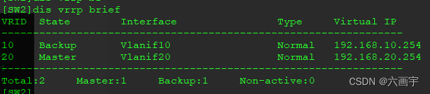
SW2
interface Vlanif10
ip address 192.168.10.253 255.255.255.0
vrrp vrid 10 virtual-ip 192.168.10.254
#
interface Vlanif20
ip address 192.168.20.253 255.255.255.0
vrrp vrid 20 virtual-ip 192.168.20.254
vrrp vrid 20 priority 120
vrrp vrid 20 track interface GigabitEthernet0/0/5 reduced 30 //检测端口
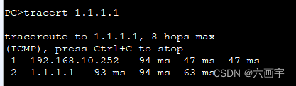
5.静态路由
SW1
ip route-static 0.0.0.0 0.0.0.0 10.0.13.3
SW2
ip route-static 0.0.0.0 0.0.0.0 10.0.23.3
AR1
ip route-static 192.168.10.0 255.255.255.0 10.0.13.1
ip route-static 192.168.10.0 255.255.255.0 10.0.23.2
ip route-static 192.168.20.0 255.255.255.0 10.0.13.1
ip route-static 192.168.20.0 255.255.255.0 10.0.23.2
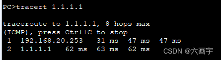
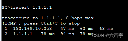
截图
1.
2.
3.
4.
5.


 1728
1728


 被折叠的 条评论
为什么被折叠?
被折叠的 条评论
为什么被折叠?
 到【灌水乐园】发言


