


Figure 1 shows the block diagram of the sensorless FOC algorithm. These blocks, which are available as IP cores, are discussed in this section.
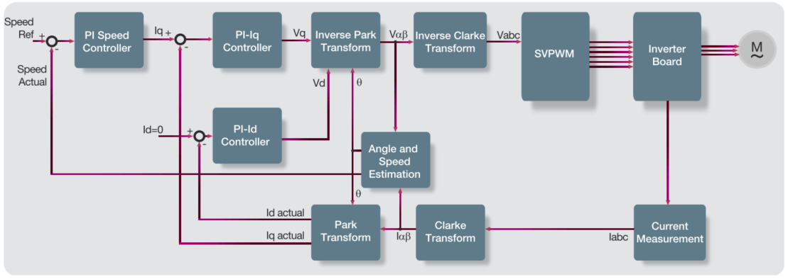
Figure 1: Block Diagram of FOC of Permanent Magnet Synchronous Motor
- PI Controller
The proportional-integral (PI) controller is a feedback mechanism that is used to control a system parameter. The PI controller has two tunable gain parameters which control the dynamic response of the controller—the proportional and integral gain constants. The proportional component of the PI controller is a product of the proportional gain constant and the error input, while the integral component is a product of the accumulated error and the integral gain constant. The two components are then added together. The integral stage of the PI controller can cause instability in the system because of uncontrolled increase in the data value. This uncontrolled rising of data is called wind-up. All PI controller implementations include an anti-windup mechanism which ensures that the controller output is limited. The Microsemi PI controller IP block uses a hold-on-saturation algorithm for anti-windup. The block also offers additional features to set the initial value of the output.
- FOC Transformations
FOC is an algorithm, which can supply optimal current to a motor by determining and controlling the torque and magnetization current components independently. In permanent magnet synchronous motors (PMSMs), the rotor is already magnetized, and hence the current supplied to the motor contributes to torque only. FOC is computationally intensive, but the Microsemi motor control reference design has been built to optimally use device resources. The FOC algorithm consists of the Clarke, Park, inverse Clarke, and inverse Park transforms.
- Position and Speed Estimator
FOC needs precise rotor position and speed as inputs. Determining rotor angle accurately is essential to ensure low power consumption. Adding physical sensors to determine position and speed add to the system cost and reduce reliability. Sensorless algorithms help in eliminating the sensor, but increase the computational complexity.
- PLL
The phase-locked loop (PLL) is used to synchronize signals. PLLs are useful in several applications, suchas angle estimation and grid-synchronization of inverters.
- Rate Limiter
The rate limiter block enables a smooth change of a variable or input to the system. For example, in a motor control system, if there is a sudden change in desired speed of the motor, the system may become unstable. To avoid such scenarios, a rate limiter block is used to transition from the initial speed to the desired speed. The rate limiter block can be configured to control the rate of change.
- Space Vector Modulation
The space vector modulation block improves DC bus utilization and eliminates short pulses to transistor switches. It improves DC bus utilization by 15% compared to using sinusoidal PWM.
- Three-Phase PWM Generation
At the end of all computations, the three phase motor voltages are available. The voltages are used to generate switching signals for transistors in the inverter. The PWM block produces switching signals for six (three high-side and three low-side) transistors, and has advanced features such as dead time and delay time insertion. The programmable dead time insertion feature helps avoid a catastrophic short circuit condition on an inverter leg which could occur because of the transistor turn-off time. The block also has a programmable delay time insertion feature, which allows synchronization of analog-to-digital converters (ADC) measurement with PWM signal generation. The block can be configured to work with inverters consisting of N-MOSFETs only or both N-MOSFETs and P-MOSFETs.
- Debugging FPGA Designs in SoC
Generally, debugging a design on a microcontroller is relatively easier compared to debugging on an FPGA. In an SoC, the high performance of an FPGA can be utilized, while retaining the advantage of faster debugging in a microcontroller. The microcontroller subsystem and the FPGA fabric in the Microsemi SmartFusion2 SoC FPGA can communicate with each other through an AMBA APB or AXI bus. This allows injecting test data into the FPGA fabric, or logging debug data from the FPGA fabric, which in-turn helps in visualizing internal data at runtime for real-time debugging. The firmware code can be run in steps and breakpoints can be set in the code to analyze the FPGA register data. The SmartFusion2 SoC FPGA based multi-axis motor control solution connects to a host PC through USB, and communicates with a graphical user interface (GUI) to start and stop the motor, set motor speed value and other system parameters, and plot upto four system variables such as motor speed, motor currents,
and rotor angle.
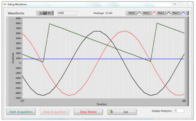
Figure 4: Screenshot of the GUI - Plotting Internal Parameters: Rotor Angle (green), Valpha (red), Vbeta (black),
Motor Speed (blue)
- Ecosystem
Microsemi provides a rich set of IP libraries consisting of IP blocks for several motor control functions that were discussed in previous sections. These blocks are customizable easily and can be ported across Microsemi devices. These blocks can be configured and connected together graphically using SmartDesign tools of Libero SoC software. With the help of these IP blocks, designers can significantly reduce the time required to implement the motor control algorithm in FPGA. These IP blocks have been tested with motors running at speeds as high as 30,000 RPM and switching frequency of 400 kHz.
- Industrial Communication Protocols
The trend in industrial networks is to migrate towards faster communication through networks instead of point-to-point communication. Implementation of such high speed communication demands for support of higher bandwidths which is not easy for a microcontroller or DSP to handle along with motor control algorithm simultaneously. In many cases, an additional microcontroller or FPGA is used to handle the communication with each motor controller. Commonly used Ethernet based protocols are Profinet, EtherNet/IP and EtherCAT standards that are still evolving. Other protocols include CAN and Modbus. The advantage of using an SoC in this context is supporting multiple industrial Ethernet protocol standards on a single FPGA platform. Depending on the end system goals, it might be possible to optimize the system for cost by reusing IP and protocol stacks (for communication), or optimize performance by carefully partitioning of the functions into hardware (FPGA) and software (ARM Cortex-M3 processor).
Microsemi's SmartFusion2 SoC FPGA has built-in CAN, high-speed USB, and a gigabit Ethernet block as part of the MSS. A high-speed SERDES block is available for implementing protocols involving serial data transfer.
Several IP blocks are available through Microsemi's IP partners. For more information, refer to .


 被折叠的 条评论
为什么被折叠?
被折叠的 条评论
为什么被折叠?
 到【灌水乐园】发言


