 基于QGIS的GIS数据投影变换实习


实习五 GIS数据的投影变换
5.1 任务要求
- 自定义坐标系统。
- 实现单点的坐标系转换。
- 实现shp和qgs格式的矢量文件的坐标系转换。
- 实现栅格文件的坐标系转换。
- 实现不同坐标系统数据的动态投影和可视化。
5.2 完成过程
5.2.1 GIS数据投影变换实现技术
在QGIS中,GIS投影变换功能的实现主要应用到了<QgsCoordinateReferenceSystem>类和<QgsCoordinateTransform>类。<QgsCoordinateReferenceSystem>类(CRS)是 QGIS 中用于表示坐标参考系统的核心类。它用于定义和操作投影信息,支持多种坐标系统(如 EPSG 代码、Proj.4 字符串等)。该类提供了设置、转换和查询坐标系的功能。
<QgsCoordinateTransform>类用于在不同的坐标参考系统(CRS)之间进行坐标转换。它可以将一个坐标系中的点转换为另一个坐标系,支持投影转换和地理坐标转换。
< QgsCoordinateReferenceSystem >类的开发文档如图5.2.1-1所示。

图5.2.1-1 < QgsCoordinateReferenceSystem >类的继承关系
与之相搭配的,< QgsCoordinateTransform >类的继承关系如图5.2.1-2所示。
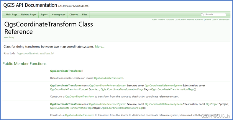
图5.2.1-2 < QgsCoordinateTransform >类的继承关系
接下来我们就如何实现基于QGIS二次开发实现GIS数据投影变换操作给出详细过程。
5.2.2 GIS数据投影变换实现过程
这里我们首先打开项目的ui文件,在主界面添加需要使用的QAction控件,分别为“shp坐标转换”、“QGIS坐标转换”、“栅格坐标转换” 和“单点坐标转换”。为了便于代码的编辑,将添加的按钮的objectName分别命名为“actionCoordTransShp”、“actionCoordTransqgis”、“actionCoordTranstif”和“actionCoordTranspoint”。操作如图5.2.2-1所示。
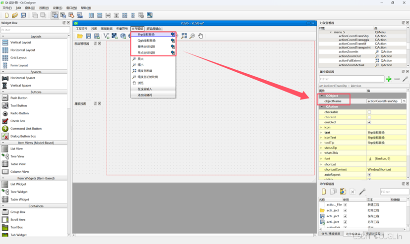
图5.2.2-1 对ui进行操作
将设定的ui进行保存后,即可回到Visual Studio中,对相应的代码进行适当的编辑。
一、坐标转换的实现
首先,需要进入头文件中,定义必要的函数,这是由于QT的信号与槽的机制,必须要进行信号与槽的相关绑定,这里我们主要预先声明了一个函数,即“on_actionCoordTrans_triggered ()”。如图5.2.2-2所示。

图5.2.2-2 声明函数
接下来,需要对声明的函数进行详细的定义。“on_actionCoordTrans_triggered ()”函数用于将当前矢量图层(Shapefile)从原始坐标参考系统(CRS)转换到目标坐标参考系统(如 UTM 区域 49),并将转换后的数据保存为新的 Shapefile 文件。转换过程包括几何坐标变换,并生成新的图层存储转换后的要素数据。操作如图5.2.2-3所示。

图5.2.2-3 定义函数
二、详细完成各类型投影的实现
接下来,需要进入头文件中,定义必要的函数,这是由于QT的信号与槽的机制,必须要进行信号与槽的相关绑定,这里我们主要预先声明了五个函数,即“on_actionCoordTrans_triggered()“函数、 “on_actionCoordTransShp_triggered()”函数、“on_actionCoordTransqgis_triggered()”函数、“on_actionCoordTranstif_triggered()”函数和“on_actionCoordTranspoint_triggered()”函数。如图5.2.2-4所示。

图5.2.2-4 声明函数
接下来,需要对声明的函数进行详细的定义。“on_actionCoordTransShp_triggered”函数用于将当前的 Shapefile 矢量图层从原始坐标参考系统(CRS)转换到目标 CRS(例如 UTM 坐标系),并将转换后的数据保存为新的 Shapefile 文件。
“on_actionCoordTransqgis_triggered”函数用于将当前 QGIS 项目的坐标参考系统转换为指定的目标 CRS(例如 UTM 坐标系),应用于整个项目。
“on_actionCoordTranstif_triggered”函数用于将当前的栅格图层(TIF 格式)从原始 CRS 转换为目标 CRS(例如 UTM 坐标系),并保存为新的 TIF 文件。
“on_actionCoordTranspoint_triggered”函数用于将一个特定的点(墨卡托坐标)转换到目标 CRS(例如 UTM 坐标系),创建一个包含转换后点的内存矢量图层,并将其添加到 QGIS 项目中。操作如图5.2.2-5所示。
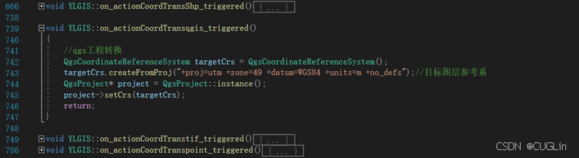
图5.2.2-5 定义函数
进行完如上步骤,编译即可得到相应具备GIS矢量数据编辑功能的系统,如图5.2.2-6所示。
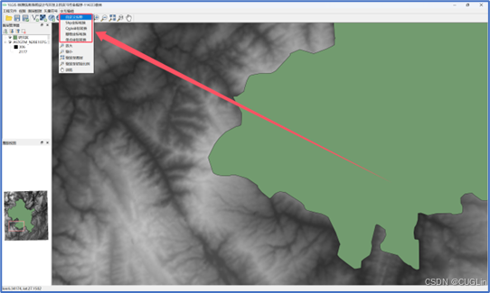
图5.2.2-6 系统界面
5.3 结果展示
完成5.2部分的系统构建后,我们便可以使用系统的GIS数据投影变换功能了,这里我们也可以进行栅格数据的投影,依次点击“交互编辑”-“自定义投影变换”,如图5.3-1所示。

图5.3-1 自定义投影变换
使用“添加矢量图层”添加一个矢量文件,点击“shp坐标转化”,便可以完成矢量数据的坐标的投影。如图5.3-2所示。
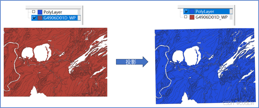
图5.3-2 shp坐标转换
这里我们也可以进行栅格数据的投影,依次点击“交互编辑”-“栅格坐标转换”,如图5.3-3所示。
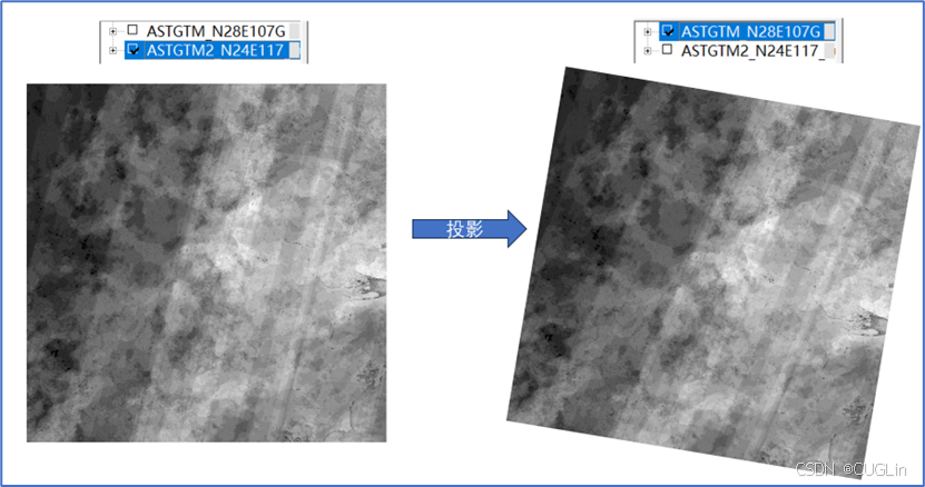
图5.3-3 栅格数据的投影
当然,这里也可以进行单点的坐标系统的转换,依次点击“交互编辑”-“单点坐标转换”如图5.3-4所示。
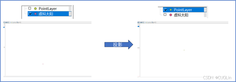
图5.3-4 单点的坐标系统的转换
同样,这里也可以进行动态投影和整体的“.qgs”文件的坐标系的转换,依次点击“交互编辑”-“qgs坐标转换”如图5.3-5所示。
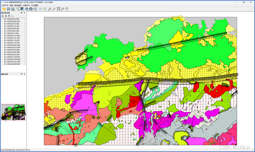
图5.3-5 动态投影
5.4 关键代码
这里的关键代码是针对GIS的投影变换操作。
具体代码的功能主要是:“on_actionCoordTrans_triggered”函数用于将当前的无定义的图层进行地理变换。
“on_actionCoordTransShp_triggered”函数用于将当前的 Shapefile 矢量图层从原始坐标参考系统(CRS)转换到目标 CRS(例如 UTM 坐标系),并将转换后的数据保存为新的 Shapefile 文件。
“on_actionCoordTransqgis_triggered”函数用于将当前 QGIS 项目的坐标参考系统转换为指定的目标 CRS(例如 UTM 坐标系),应用于整个项目。
“on_actionCoordTranstif_triggered”函数用于将当前的栅格图层(TIF 格式)从原始 CRS 转换为目标 CRS(例如 UTM 坐标系),并保存为新的 TIF 文件。
“on_actionCoordTranspoint_triggered”函数用于将一个特定的点(墨卡托坐标)转换到目标 CRS(例如 UTM 坐标系),创建一个包含转换后点的内存矢量图层,并将其添加到 QGIS 项目中。
源代码如下:
//自定义地理坐标系
void YLGIS::on_CustomCRS_triggered()
{
    // 创建一个 QDialog 对象
    QDialog* pdDialog = new QDialog(this);
    pdDialog->setWindowTitle(QString::fromLocal8Bit("Custom CRS"));
    pdDialog->setFixedWidth(500);  // 设置窗口宽度

    QVBoxLayout* plBoxLayout = new QVBoxLayout(pdDialog); // 创建布局
    // 输入框:CRS 名称
    QLineEdit* peCrsNameEdit = new QLineEdit(pdDialog);
    peCrsNameEdit->setPlaceholderText(QString::fromLocal8Bit("Inport the CRS name"));
    plBoxLayout->addWidget(peCrsNameEdit);
    // 输入框:PROJ 字符串
    QLineEdit* peProjStringEdit = new QLineEdit(pdDialog);
    peProjStringEdit->setPlaceholderText(QString::fromLocal8Bit("Inport the Proj string"));
    plBoxLayout->addWidget(peProjStringEdit);
    // 创建按钮
    QDialogButtonBox* pbButtonBox = new QDialogButtonBox(QDialogButtonBox::Ok | QDialogButtonBox::Cancel, pdDialog);
    plBoxLayout->addWidget(pbButtonBox);
    pdDialog->setLayout(plBoxLayout); // 设置布局
    // 连接信号和槽
    connect(pbButtonBox, &QDialogButtonBox::accepted, pdDialog, &QDialog::accept);
    connect(pbButtonBox, &QDialogButtonBox::rejected, pdDialog, &QDialog::reject);
    // 显示对话框
    if (pdDialog->exec() == QDialog::Accepted) {
        QString sCrsName = peCrsNameEdit->text();
        QString sProjString = peProjStringEdit->text();
        // 检查输入
        if (sCrsName.isEmpty() || sProjString.isEmpty()) {
            QMessageBox::warning
            (
                this,
                QString::fromLocal8Bit("输入错误"),
                QString::fromLocal8Bit("坐标系名称或投影字符串不能为空!")
            );
            return;
        }
        CustomCRS cCustomCRS;
        if (cCustomCRS.addCustomCRS(sCrsName, sProjString)) {
            QMessageBox::information
            (
                this,
                QString::fromLocal8Bit("成功"),
                QString::fromLocal8Bit("自定义坐标系添加成功")
            );
        }
        else {
            QMessageBox::warning
            (
                this,
                QString::fromLocal8Bit("错误"),
                QString::fromLocal8Bit("自定义坐标系添加失败")
            );
        }
    }
    delete pdDialog;  // 清理资源
}
//shp坐标系转换
void YLGIS::on_actionCoordTransShp_triggered()
{
	//shp文件转换
	QgsVectorLayer* layer = (QgsVectorLayer*)m_curMapLayer;
	QString outputFile = QStringLiteral("E:/output.shp");;
	if (layer == nullptr || !layer->isValid() || QgsMapLayerType::VectorLayer != m_curMapLayer->type())
	{
		return;
	}
	//确定原始图层的参考系和目标图层的参考系
	QString targetCrsCode = "EPSG:4326";
	QgsCoordinateReferenceSystem shpCrs = layer->crs();//原始图层参考系
	QgsCoordinateReferenceSystem targetCrs = QgsCoordinateReferenceSystem();
	targetCrs.createFromProj("+proj=utm +zone=49 +datum=WGS84 +units=m +no_defs");//目标图层参考系
	if (!targetCrs.isValid()) {
		qDebug() << "目标图层参考系无效:" << targetCrs.authid();
		return;
	}
	//构造坐标转换对象
	QString srsDbName = QgsApplication::srsDatabaseFilePath();
	QgsCoordinateTransform* pTransform = new QgsCoordinateTransform(shpCrs, targetCrs, QgsProject::instance());
	if (pTransform == nullptr || !pTransform->isValid())
	{
		return;
	}
	//对图层中每一个要素进行转换,将转换后的结果放入postRansfeatureLIst中
	QgsFeatureList postTransfeatureList;
	QgsFeatureIterator iter = layer->getFeatures();
	QgsFeature feature;
	while ((iter.nextFeature(feature)))
	{
		QgsGeometry g = feature.geometry();
		QgsAttributes f = feature.attributes();
		//transform函数就是转换函数,将每一个geometry进行转换
		//QgsGeometry是基类,transform函数是个虚函数
		//根据具体的类型调用各自Geometry中的transfrom
		//具体的转换可以参考QgsGeometry的子类的transform
		if (g.transform(*pTransform) == 0)
		{
			feature.setGeometry(g);
		}
		else
		{
			feature.clearGeometry();
		}
		postTransfeatureList << feature;
	}
	//创建一个新shp,将转换后的postTransfeatureList存入新的shp中
	QString errorMessage;
	const QString fileFormat = "ESRI Shapefile";
	const QString enc = "System";
	QgsFields fields = layer->fields();
	QgsVectorLayer* targetLayer = createTempLayer(layer->geometryType(), targetCrs.authid(), fields, postTransfeatureList);
	QString errMsg;
	QgsVectorFileWriter::SaveVectorOptions saveOptions;
	saveOptions.fileEncoding = targetLayer->dataProvider()->encoding();
	saveOptions.driverName = "ESRI Shapefile";
	targetLayer->setCrs(targetCrs);//再设置一次!
	QgsVectorFileWriter::WriterError err = QgsVectorFileWriter::writeAsVectorFormatV2(targetLayer, outputFile, targetLayer->transformContext(), saveOptions, nullptr, nullptr, &errMsg);
	if (err != QgsVectorFileWriter::WriterError::NoError)
	{
		return;
	}
	QgsProject::instance()->addMapLayer(targetLayer);
	return;
}
//qgs坐标转换
void YLGIS::on_actionCoordTransqgis_triggered()
{
	//qgs工程转换
	QgsCoordinateReferenceSystem targetCrs = QgsCoordinateReferenceSystem();
	targetCrs.createFromProj("+proj=utm +zone=49 +datum=WGS84 +units=m +no_defs");//目标图层参考系
	QgsProject* project = QgsProject::instance();
	project->setCrs(targetCrs);
	return;
}
//栅格坐标系转换
void YLGIS::on_actionCoordTranstif_triggered()
{
	//tif转换
	QgsRasterLayer* layer = (QgsRasterLayer*)m_curMapLayer;
	QString outputFile = QStringLiteral("E:/output.tif");;
	if (layer == nullptr || !layer->isValid())
	{
		return;
	}
	//确定原始图层的参考系和目标图层的参考系
	QString targetCrsCode = "EPSG:4326";
	QgsCoordinateReferenceSystem shpCrs = layer->crs();//原始图层参考系
	QgsCoordinateReferenceSystem targetCrs = QgsCoordinateReferenceSystem();
	targetCrs.createFromProj("+proj=utm +zone=49 +datum=WGS84 +units=m +no_defs");//目标图层参考系
	layer->setCrs(targetCrs);
	if (!targetCrs.isValid()) {
		qDebug() << "目标图层参考系无效:" << targetCrs.authid();
		return;
	}
	QgsRasterFileWriter writer(outputFile);
	// 创建一个QgsRasterPipe对象并设置渲染器
	QgsRasterPipe pipe;
	pipe.set(layer->dataProvider()->clone());
	// 创建一个QgsRasterBlockFeedback对象
	QgsRasterBlockFeedback feedback;
	// 写入新的tif文件
	//writer.writeRaster(&pipe, layer->width(), layer->height(), layer->extent(), layer->crs(), &feedback);
	QgsProject::instance()->addMapLayer(layer);
	return;
}
//点坐标坐标转换
void YLGIS::on_actionCoordTranspoint_triggered()
{
	QgsPointXY curPoint(11472426, 4197692);
	QgsCoordinateReferenceSystem srcCrs = QgsCoordinateReferenceSystem(); // 墨卡托坐标
	srcCrs.createFromProj("+proj=merc +lon_0=0 +k=1 +x_0=0 +y_0=0 +datum=WGS84 +units=m +no_defs");
	QgsCoordinateReferenceSystem dstCrs = QgsCoordinateReferenceSystem();
	dstCrs.createFromProj("+proj=utm +zone=49 +datum=WGS84 +units=m +no_defs");// WSG84坐标
	QgsCoordinateTransform* crsTras = new QgsCoordinateTransform(srcCrs, dstCrs, QgsProject::instance());
	if (crsTras == nullptr || !crsTras->isValid())
	{
		return;
	}
	auto tmpPt = crsTras->transform(curPoint);
	QgsPoint* newPoint = new QgsPoint();
	newPoint->setX(tmpPt.x());
	newPoint->setY(tmpPt.y());
	QList<QgsField> fields;
	fields.append(QgsField("id", QVariant::Int)); // 添加一个字段
	QgsVectorLayer* pointLayer = new QgsVectorLayer("Point?crs=EPSG:4326", "PointLayer", "memory");
	if (!pointLayer) {
		qWarning() << "Layer not created!";
		return;
	}
	// 设置字段
	pointLayer->dataProvider()->addAttributes(fields);
	pointLayer->updateFields();
	// 创建要素
	QgsFeature feature;
	feature.setGeometry(QgsGeometry::fromPointXY(*newPoint)); // 使用 newPoint 设置几何体
	feature.setAttributes(QgsAttributes() << 1); // 设置属性,这里示例为 ID 为 1
	// 将要素添加到图层
	pointLayer->dataProvider()->addFeature(feature);
	pointLayer->updateExtents();
	// 将图层添加到地图画布
	QgsProject::instance()->addMapLayer(pointLayer);
}


 3001
3001

 被折叠的 条评论
为什么被折叠?
被折叠的 条评论
为什么被折叠?
 到【灌水乐园】发言


