


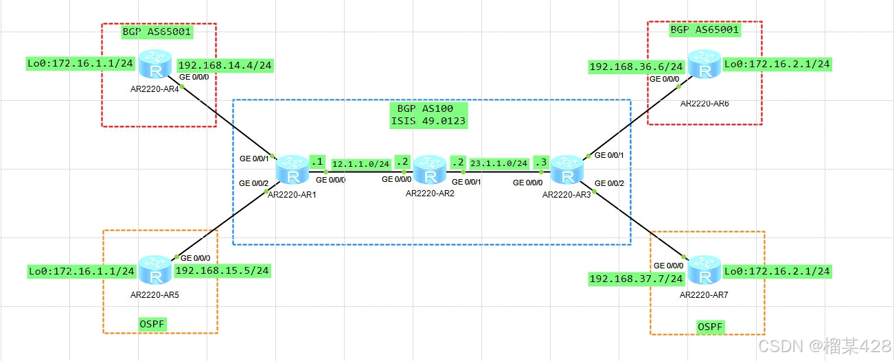
一、 实验拓扑
二、 实验需求及解法
本实验模拟ISP为企业用户提供MPLS-VPN的网络环境。
R1/2/3为ISP设备,组成公网MPLS域。
R4/6是客户A设备,R5/7是客户B设备。
完成以下需求:
1.如图所示,配置各设备IP地址
ISP设备R1/2/3都有环回口Lo0,地址如下:
R1:1.1.1.1/32
R2:2.2.2.2/32
R3:3.3.3.3/32
R1/3与客户互联接口,划分VRF后再配置IP地址。
R1:
interface GigabitEthernet0/0/0
ip address 12.1.1.1 255.255.255.0
interface LoopBack0
ip address 1.1.1.1 255.255.255.255

R2:
interface GigabitEthernet0/0/0
ip address 12.1.1.2 255.255.255.0
interface GigabitEthernet0/0/1
ip address 23.1.1.2 255.255.255.0
interface LoopBack0
ip address 2.2.2.2 255.255.255.255

R3:
interface GigabitEthernet0/0/0
ip address 23.1.1.3 255.255.255.0
interface LoopBack0
ip address 3.3.3.3 255.255.255.255

R4:
interface GigabitEthernet0/0/0
ip address 192.168.14.4 255.255.255.0
interface LoopBack0
ip address 172.16.1.1 255.255.255.0

R5:
interface GigabitEthernet0/0/0
ip address 192.168.15.5 255.255.255.0
interface LoopBack0
ip address 172.16.1.1 255.255.255.0

R6:
interface GigabitEthernet0/0/0
ip address 192.168.36.6 255.255.255.0
interface LoopBack0
ip address 172.16.2.1 255.255.255.0

R7:
interface GigabitEthernet0/0/0
ip address 192.168.37.7 255.255.255.0
interface LoopBack0
ip address 172.16.2.1 255.255.255.0
2.ISP网络,配置R1/2/3
2.1运行IGP协议,满足以下需求:
2.1.1 运行ISIS,进程号1,区域号49.0123
2.1.2 系统ID如下:
R1:0000.0000.0001
R2:0000.0000.0002
R3:0000.0000.0003
2.1.3 所有设备均为level-2路由器。
2.1.4 激活所有公网接口。
2.1.5 确认ISP公网互通。
R1:
isis 1
is-level level-2
network-entity 49.0123.0000.0000.0001.00
interface GigabitEthernet0/0/0
isis enable 1
interface LoopBack0
isis enable 1

R2:
isis 1
is-level level-2
network-entity 49.0123.0000.0000.0002.00
interface GigabitEthernet0/0/0
isis enable 1
interface GigabitEthernet0/0/1
isis enable 1
interface LoopBack0
isis enable 1

R3:
isis 1
is-level level-2
network-entity 49.0123.0000.0000.0003.00
interface GigabitEthernet0/0/0
isis enable 1
interface LoopBack0
isis enable 1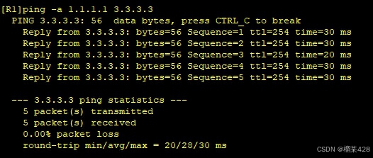
2.2 运行BGP协议,满足以下需求:
2.2.1 AS号100,手动设置RID为Loopback0地址。
2.2.2 关闭BGP默认建立ipv4邻居功能
2.2.3 R1与R3使用Looback0建立vpnv4邻居。
2.2.4 R2不运行BGP
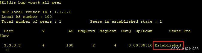
2.2.5 确认R1/3邻居关系。
R1:
bgp 100
router-id 1.1.1.1
undo default ipv4-unicast
peer 3.3.3.3 as-number 100
peer 3.3.3.3 connect-interface LoopBack0
ipv4-family vpnv4
peer 3.3.3.3 enable

R3:
bgp 100
router-id 3.3.3.3
undo default ipv4-unicast
peer 1.1.1.1 as-number 100
peer 1.1.1.1 connect-interface LoopBack0
ipv4-family vpnv4
peer 1.1.1.1 enable
[R1]dis bgp vpnv4 all peer \\注意此时查看vpnv4邻居,而不是ipv4邻居。
2.3 运行MPLS协议,满足以下需求:
2.3.1 LSR-ID为Loopback0地址
2.3.2 启用LDP,自动分发标签。
R1:
mpls lsr-id 1.1.1.1
mpls
mpls ldp
interface GigabitEthernet0/0/0
mpls
mpls ldp
R2:
mpls lsr-id 2.2.2.2
mpls
mpls ldp
interface GigabitEthernet0/0/0
mpls
mpls ldp
interface GigabitEthernet0/0/1
mpls
mpls ldp
R3:
mpls lsr-id 3.3.3.3
mpls
mpls ldp
interface GigabitEthernet0/0/0
mpls
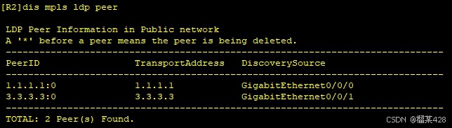
mpls ldp[R2]dis mpls ldp peer \\查看LDP邻居
3.配置MPLS-VPN
3.1 客户A与ISP之间运行BGP,满足以下需求:
3.1.1 R1创建VRF(vpn-instance),名称4,RD 4:4,出方向RT(vpn-target)4:6 R3创建VRF,名称6,RD 6:6,出方向RT6:4 R1/3配置合适的入方向RT,接收对端vpnv4路由。
R1:
ip vpn-instance 4
ipv4-family
route-distinguisher 4:4
vpn-target 4:6 export-extcommunity
vpn-target 6:4 import-extcommunity
R3:
ip vpn-instance 6
ipv4-family
route-distinguisher 6:6
vpn-target 6:4 export-extcommunity
vpn-target 4:6 import-extcommunity
3.1.2 R1将G0/0/1划入VRF4,IP地址192.168.14.1/24
R3将G0/0/1划入VRF6,IP地址192.168.36.3/24
R1:
interface GigabitEthernet0/0/1
ip binding vpn-instance 4
ip address 192.168.14.1 255.255.255.0
R3:
interface GigabitEthernet0/0/1
ip binding vpn-instance 6
ip address 192.168.36.3 255.255.255.0
3.1.3 R1/4,R3/6分别使用物理口建立EBGP邻居关系。
R1:
bgp 100
ipv4-family vpn-instance 4
peer 192.168.14.4 as-number 65001

R4:
bgp 65001
peer 192.168.14.1 as-number 100

R3:
bgp 100
ipv4-family vpn-instance 6
peer 192.168.36.6 as-number 65001

R6:
bgp 65001
peer 192.168.36.3 as-number 100
[R1]dis bgp vpnv4 all peer \\R1认为R4是vpnv4邻居
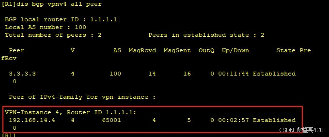
[R4]dis bgp peer \\R4认为R1是ipv4邻居

R3/6同理。
3.1.4 R4宣告172.16.1.0/24,R6宣告172.16.2.0/24
R4:
bgp 65001
network 172.16.1.0 255.255.255.0
R6:
bgp 65001
network 172.16.2.0 255.255.255.0
3.1.5 由于R4/6的AS号相同,配置允许接收同as路由。(allow-as-loop)
R4:
bgp 65001
peer 192.168.14.1 allow-as-loop
R6:
bgp 65001
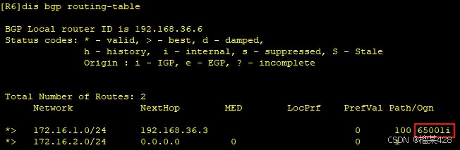
peer 192.168.36.3 allow-as-loop [R4]dis bgp routing-table \\收到和本地AS相同的路由
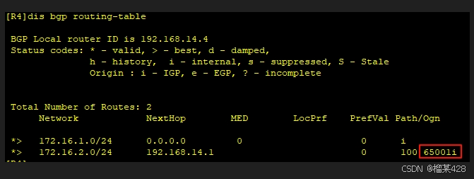
[R6]dis bgp routing-table
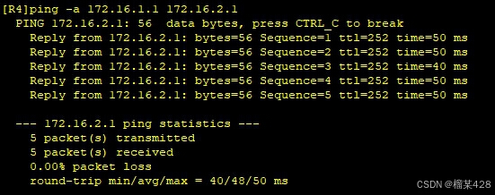
3.1.6 确认客户A的172.16.1.1与172.16.2.1互通。
3.2 客户B与ISP之间运行OSPF,满足以下需求:
3.2.1 R1创建VRF,名称5,RD5:5,出方向RT5:7
R3创建VRF,名称7,RD7:7,出方向RT7:5
R1/3配置合适的入方向RT,接收对端vpnv4路由。
R1:
ip vpn-instance 5
ipv4-family
route-distinguisher 5:5
vpn-target 5:7 export-extcommunity
vpn-target 7:5 import-extcommunity

R3:
ip vpn-instance 7
ipv4-family
route-distinguisher 7:7
vpn-target 7:5 export-extcommunity
vpn-target 5:7 import-extcommunity
3.2.2 R1将G0/0/2划入VRF5,IP地址192.168.15.1/24
R3将G0/0/2划入VRF7,IP地址192.168.37.3/24
R1:
interface GigabitEthernet0/0/2
ip binding vpn-instance 5
ip address 192.168.15.1 255.255.255.0

R3:
interface GigabitEthernet0/0/2
ip binding vpn-instance 7
ip address 192.168.37.3 255.255.255.0
3.2.3 R1/5,R3/7建立OSPF邻居关系。
1)进程1,手动设置RID如下:
R1:1.1.1.1 R5:5.5.5.5
R3:3.3.3.3 R7:7.7.7.7
2)注意R1/3的OSPF需要划入对应VRF。
3) 所有接口都属于区域0 4)使用network命令宣告,通配符0.0.0.0
R1:
ospf 1 router-id 1.1.1.1 vpn-instance 5
area 0.0.0.0
network 192.168.15.1 0.0.0.0
R5:
ospf 1 router-id 5.5.5.5’
area 0.0.0.0
network 172.16.1.1 0.0.0.0
network 192.168.15.5 0.0.0.0
R3:
ospf 1 router-id 3.3.3.3 vpn-instance 7
area 0.0.0.0
network 192.168.37.3 0.0.0.0
R7:
ospf 1 router-id 7.7.7.7
area 0.0.0.0
network 172.16.2.1 0.0.0.0
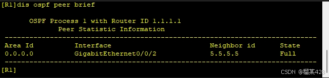
network 192.168.37.7 0.0.0.0 [R1]dis ospf peer brief \\OSPF可以直接查看VRF邻居
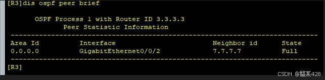
[R3]dis ospf peer brief
3.2.4 在R1/3上,将OSPF引入BGP。(无策略)
R1:
bgp 100
ipv4-family vpn-instance 5
import-route ospf 1
R3:
bgp 100
ipv4-family vpn-instance 7
import-route ospf 1
3.2.5 在R1/3上,将BGP引入OSPF。(无策略)
R1:
ospf 1 router-id 1.1.1.1 vpn-instance 5
import-route bgp
R3:
ospf 1 router-id 3.3.3.3 vpn-instance 7
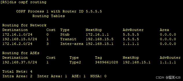
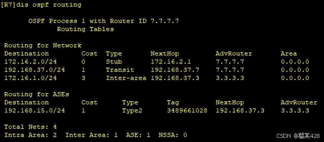
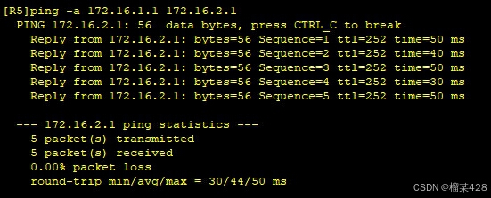
import-route bgp 3.2.6 确认客户B的172.16.1.1和172.16.2.1互通。
R5和R7的Loopback0有预配ospf network-type broadcast
所以会根据接口配置产生24位路由。
[R5]dis ospf routing
[R7]dis ospf routing


 1189
1189

 被折叠的 条评论
为什么被折叠?
被折叠的 条评论
为什么被折叠?
 到【灌水乐园】发言


