


DAPLink源码固件编译与制作
- 📍个人制作调试烧录器相关篇《【开源电路】ST-LINKv2/V2-1/DAP/J-LINK-OB 烧录器》
- ✨这里以Air/stm
32f103cbt6固件编译为例。 - 📌DAPLink源码地址:
https://github.com/ARMmbed/DAPLink - 🥕其它比较有人气的DAP开源工程:
https://github.com/wuxx/nanoDAP - 🔖 如果不想自己生成,可以使用合宙提供的现成的工程以及固件;
https://gitee.com/openLuat/daplink/tree/main,但是需要注意,适配的是216MHz主频。
- 👉原项目地址页面,目前已经无法访问,个人提供以前下载下来的资源,并重新上传到个人gitee项目:
https://gitee.com/perseverance51/air32-daplink/tree/master
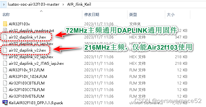
- 🎉现成的固件下载地址:
https://gitee.com/openLuat/luatos-soc-air32f103/tree/master/AIR_Jlink_Keil(其中v1为72MHz主频的,v2为216MHz主频的,不通用其他品牌同型号使用)
- 🍕或者在上面的DAPLINK项目里,最终版本固件资源页面,可以下载到包含stm32f103型号的daplink固件(
https://github.com/ARMmbed/DAPLink/releases/tag/v0257)
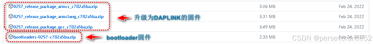
- 🔰合宙提供的固件说明:
- ⚡合宙提供的DAPLink源码说明:
- 🔰主频参数做了修改:
- 🔖使用合宙提供的源码工程,还需要拷贝DAPLink源码工程中的
version_git.h文件,或者修改对应的宏,否则会报错,找不到头文件。
- 📓stm32其他型号制作,可以参考DAPLINK源码生成的Keil工程目录型号列表:
📗nanoDAP开源项目固件简要说明
✨以v2.3为例,原理图和ST-LINKV2基本通用,具体详情可以查看
nanoDAP\hardware\V2.3\nanoDAP.pdf原理图。
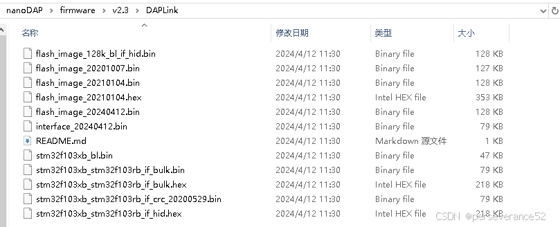
- 🌿编译好的固件:
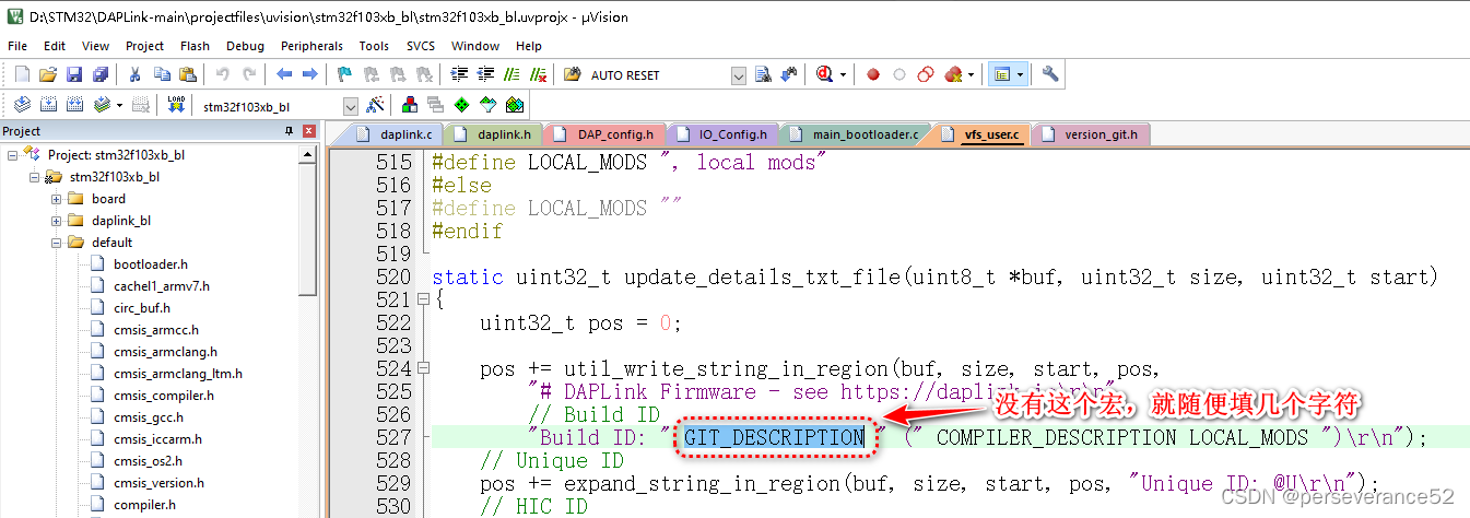
- 🌿如果自己直接打包下载的nanoDAP原创进行固件编译,需要添加
version_git.h头文件到目录nanoDAP\software\DAPLink\source\daplink目录下:
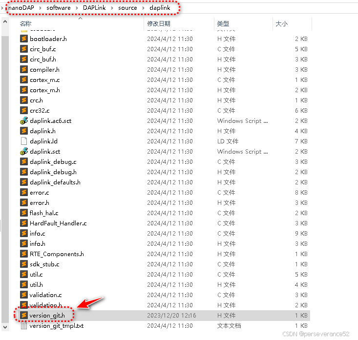
-📄version_git.h头文件内容格式如下,宏GIT_DESCRIPTION、GIT_COMMIT_SHA可以随便填写
#ifndef VERSION_GIT_H
#define VERSION_GIT_H

#define GIT_DESCRIPTION  "123456"
#define GIT_COMMIT_SHA  "123456"
#define GIT_LOCAL_MODS  1

#endif
🈯需要使用到的CMD命令集合
python.exe -m pip install --upgrade pip --升级pip命令
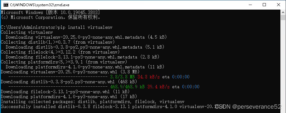
pip install virtualenv 安装虚拟环境
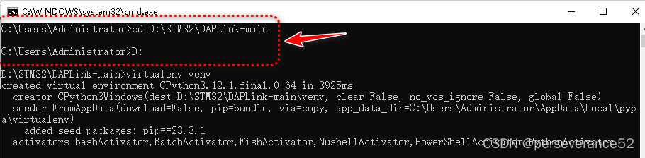
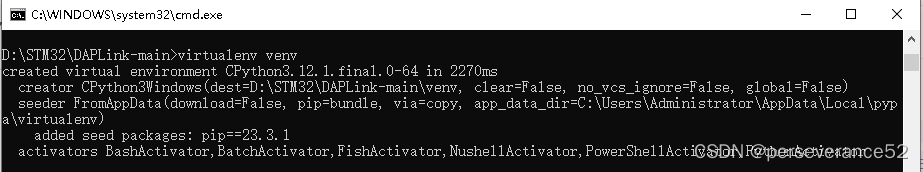
virtualenv venv --创建虚拟环境
cd D:\STM32\DAPLink-main\venv -- 进入虚拟环境文件夹
venv/Scripts/activate.bat -- 执行激活虚拟环境
cd D:\STM32\DAPLink-main\ -- 返回主目录
pip install -r requirements.txt -- 安装所需组件
progen generate -t uvision -- 生成Keil工程列表
venv/Scripts/deactivate.bat -- 退出虚拟环境
🛠固件编译前的环境搭建
- 🌿需要安装Python3,并且将Python路径添加到系统环境变量中。
- 📍Python下载地址:
https://www.python.org/getit/
-
🌿Windows环境下,
Python虚拟环境的搭建::pip install virtualenv安装虚拟环境
-
🌿在cmd命令提示符窗口内,通过cd命令进入到所下载下来的并解压的DAPLink源码文件夹内:
cd D:\STM32\DAPLink-main
-
🌿在
.\DAPLink-main源码所在文件夹内,创建虚拟环境:virtualenv venv,会随之创建一个名为venv文件夹。
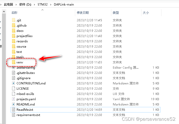
- 🌿通过cd命令进入到
venv文件夹内:
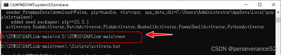
- 🌿执行
.\Scripts\activate.bat命令.激活虚拟环境
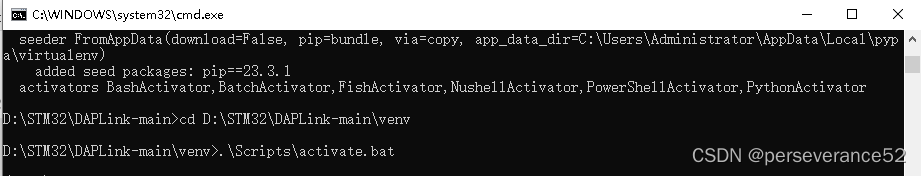
✨上面2个步骤可以合并,直接在
DAPLink-main源码所在文件位置,执行.venv\Scripts\activate.bat
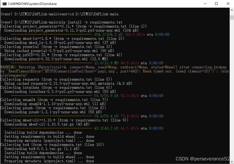
- 🌿f返回源目录:
cd D:\STM32\DAPLink-main\;执行:pip install -r requirements.txt,安装所需组件。
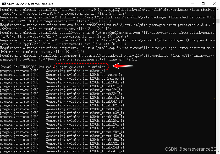
- 🌿在
DAPLink-main目录下,执行progen generate -t uvision;生成Keil工程列表
- 🌿退出虚拟环境
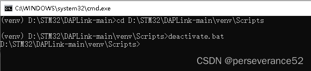
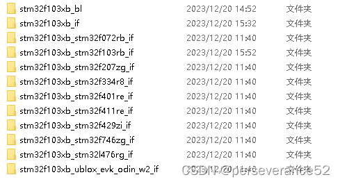
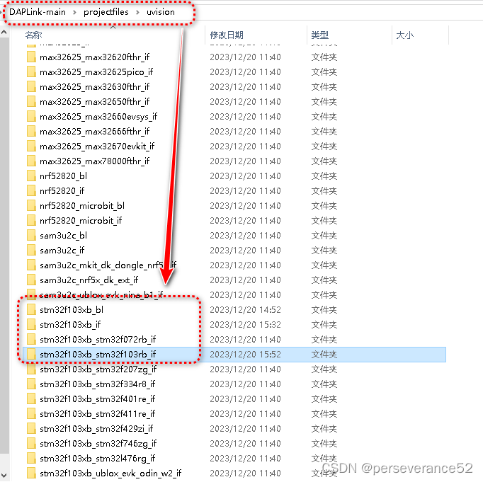
- ✨在
DAPLink-main\projectfiles\uvision路径下的得到下面的工程列表,我们只需要保留其中的2个工程:(经常测试stm32f103xb_if生成的Hex也可以作为daplink IAP升级固件)
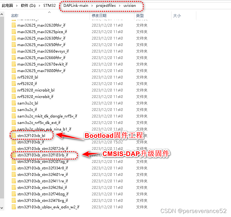
- ✨工程说明:
stm32f103xb_bl:Bootload固件,支持拖拽升级
stm32f103xb_stm32f103rb_if:实际实现dap功能的工程
- 📢烧录完成stm32f103xb_bl.Hex固件后,通过USB(P11,PA12)连接电脑,会出现一个64M的U盘,让后将
stm32f103xb_stm32f103rb_if工程生成的Hex文件拷贝到U盘中完成DAPLINK功能升级。
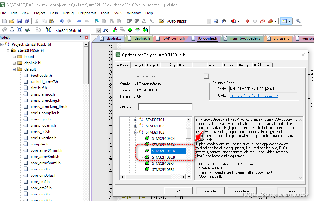
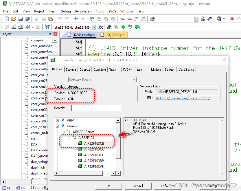
🔨工程编译
- 🔖以stmAir32F103c8t6为例,型号选择:✨选择stm32/Air32F103C8t6作为对象都可以正常编译。
- 📢由于工程中的头文件路径依赖关系,工程目录结构不能随意移动。(如需拷贝,需要将
DAPLink-main目录全部拷贝)。
- 👉这里需要根据具体使用的单片机型号选择对于的工程。
-
- 🌿对于使用
stm/Air32f103CxTx单片机,那么这里可以选择:
- 🌿对于使用
stm32f103xb_bl//Bootload程序
stm32f103xb_if//IAP升级程序
-
- 🌿对于使用
stm/Air32f103RxTx单片机,那么这里可以选择:
- 🌿对于使用
stm32f103xb_bl//Bootload程序
stm32f103rb_if//IAP升级程序
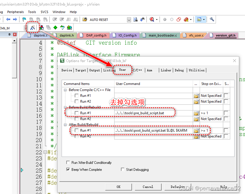
- 🌿
options for Target选项-User
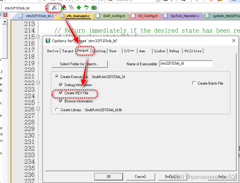
- 🌿勾选生成Hex文件
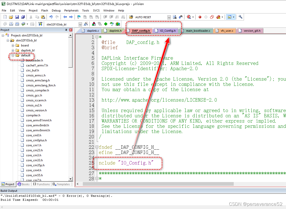
🛠相关参数配置
- 🌿相关引脚配置都在
IO_Config.h文件中:
/**
 * @file    IO_Config.h
 * @brief
 *
 * DAPLink Interface Firmware
 * Copyright (c) 2009-2016, ARM Limited, All Rights Reserved
 * SPDX-License-Identifier: Apache-2.0
 *
 * Licensed under the Apache License, Version 2.0 (the "License"); you may
 * not use this file except in compliance with the License.
 * You may obtain a copy of the License at
 *
 * http://www.apache.org/licenses/LICENSE-2.0
 *
 * Unless required by applicable law or agreed to in writing, software
 * distributed under the License is distributed on an "AS IS" BASIS, WITHOUT
 * WARRANTIES OR CONDITIONS OF ANY KIND, either express or implied.
 * See the License for the specific language governing permissions and
 * limitations under the License.
 */

#ifndef __IO_CONFIG_H__
#define __IO_CONFIG_H__

#include "stm32f1xx.h"
#include "compiler.h"
#include "daplink.h"

COMPILER_ASSERT(DAPLINK_HIC_ID == DAPLINK_HIC_ID_STM32F103XB);

//USB control pin
#define USB_CONNECT_PORT_ENABLE()    __HAL_RCC_GPIOA_CLK_ENABLE()
#define USB_CONNECT_PORT_DISABLE()   __HAL_RCC_GPIOA_CLK_DISABLE()
#define USB_CONNECT_PORT             GPIOA
#define USB_CONNECT_PIN              GPIO_PIN_15
#define USB_CONNECT_ON()             (USB_CONNECT_PORT->BSRR = USB_CONNECT_PIN)
#define USB_CONNECT_OFF()            (USB_CONNECT_PORT->BRR  = USB_CONNECT_PIN)

//Connected LED
#define CONNECTED_LED_PORT           GPIOB
#define CONNECTED_LED_PIN            GPIO_PIN_11
#define CONNECTED_LED_PIN_Bit        11

//When bootloader, disable the target port(not used)
#define POWER_EN_PIN_PORT            GPIOB
#define POWER_EN_PIN                 GPIO_PIN_15
#define POWER_EN_Bit                 15

// nRESET OUT Pin
#define nRESET_PIN_PORT              GPIOB
#define nRESET_PIN                   GPIO_PIN_0
#define nRESET_PIN_Bit               0

//SWD
#define SWCLK_TCK_PIN_PORT           GPIOB
#define SWCLK_TCK_PIN                GPIO_PIN_13
#define SWCLK_TCK_PIN_Bit            13

#define SWDIO_OUT_PIN_PORT           GPIOB
#define SWDIO_OUT_PIN                GPIO_PIN_14
#define SWDIO_OUT_PIN_Bit            14

#define SWDIO_IN_PIN_PORT            GPIOB
#define SWDIO_IN_PIN                 GPIO_PIN_12
#define SWDIO_IN_PIN_Bit             12

//JTAG
#define TDO_PIN_PORT                 GPIOA
#define TDO_PIN                      GPIO_PIN_10
#define TDO_PIN_Bit                  10

#define TDI_PIN_PORT                 GPIOA
#define TDI_PIN                      GPIO_PIN_9
#define TDI_PIN_Bit                  9

//LEDs
//USB status LED
#define RUNNING_LED_PORT             GPIOA
#define RUNNING_LED_PIN              GPIO_PIN_2
#define RUNNING_LED_Bit              2

#define PIN_HID_LED_PORT             GPIOA
#define PIN_HID_LED                  GPIO_PIN_6
#define PIN_HID_LED_Bit              6

#define PIN_CDC_LED_PORT             GPIOA
#define PIN_CDC_LED                  GPIO_PIN_10
#define PIN_CDC_LED_Bit              10

#define PIN_MSC_LED_PORT             GPIOA
#define PIN_MSC_LED                  GPIO_PIN_0
#define PIN_MSC_LED_Bit              0


#endif
- 🔨设备虚拟U盘,显示容量大小调整位置:
vfs_user.c
//! @brief Size in bytes of the virtual disk.
//!
//! Must be bigger than 4x the flash size of the biggest supported
//! device.  This is to accomodate for hex file programming.
#define VFS_DISK_SIZE (MB(64))
- 🔧设备显示名称调整位置:
stm32f103rb.c
const board_info_t g_board_info = {
    .info_version = kBoardInfoVersion,
    .board_id = "0001",
    .family_id = kStub_HWReset_FamilyID,
    .target_cfg = &target_device,
    .board_vendor = "ANY",
    .board_name = "STM32 DAPLink",
};
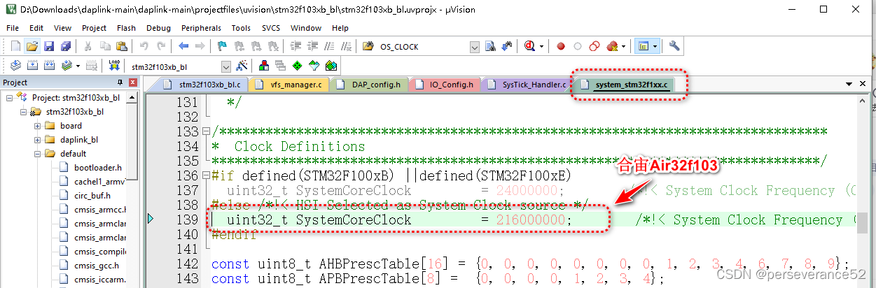
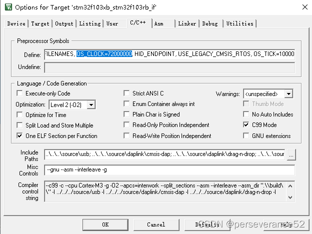
- ⌛主时钟频率(
SystemCoreClock)调整位置:system_stm32f1xx.c
/*******************************************************************************
*  Clock Definitions
*******************************************************************************/
#if defined(STM32F100xB) ||defined(STM32F100xE)
  uint32_t SystemCoreClock         = 24000000;        /*!< System Clock Frequency (Core Clock) */
#else /*!< HSI Selected as System Clock source */
  uint32_t SystemCoreClock         = 72000000;        /*!< System Clock Frequency (Core Clock) */
#endif
- ✨虽然宏中有定义
OS_CLOCK=72000000,,个人认为,起作用的还是上面代码。
- ⏰外部时钟晶振参数调整位置:
stm32f1xx_hal_conf.h
/**
  * @brief Internal High Speed oscillator (HSI) value.
  *        This value is used by the RCC HAL module to compute the system frequency
  *        (when HSI is used as system clock source, directly or through the PLL).
  */
#if !defined  (HSI_VALUE)
  #define HSI_VALUE    ((uint32_t)8000000) /*!< Value of the Internal oscillator in Hz*/
#endif /* HSI_VALUE */
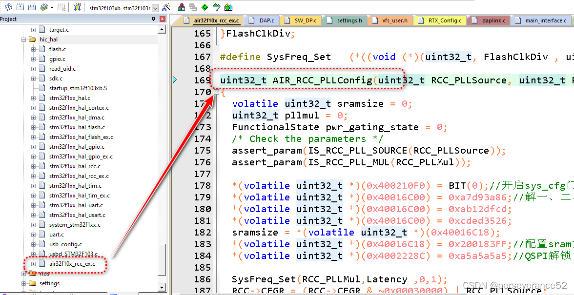
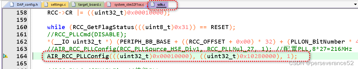
- ⏱时钟主频配置函数位置:
sdk.c
/**
    * @brief  Switch the PLL source from HSI to HSE bypass, and select the PLL as SYSCLK
  *         source.
  *         The system Clock is configured as follow :
  *            System Clock source            = PLL (HSE bypass)
  *            SYSCLK(Hz)                     = 72000000
  *            HCLK(Hz)                       = 72000000
  *            AHB Prescaler                  = 1
  *            APB1 Prescaler                 = 2
  *            APB2 Prescaler                 = 1
  *            HSE Frequency(Hz)              = 8000000
  *            HSE PREDIV1                    = 1
  *            PLLMUL                         = 9
  *            Flash Latency(WS)              = 2
  * @param  None
  * @retval None
  */
void sdk_init()
{
    RCC_ClkInitTypeDef RCC_ClkInitStruct = {0};
    RCC_OscInitTypeDef RCC_OscInitStruct = {0};

    SystemCoreClockUpdate();
    HAL_Init();

    /* Select HSI as system clock source to allow modification of the PLL configuration */
    RCC_ClkInitStruct.ClockType = RCC_CLOCKTYPE_SYSCLK;
    RCC_ClkInitStruct.SYSCLKSource = RCC_SYSCLKSOURCE_HSI;
    if (HAL_RCC_ClockConfig(&RCC_ClkInitStruct, FLASH_LATENCY_1) != HAL_OK) {
        /* Initialization Error */
        util_assert(0);
    }

    /* Enable HSE bypass Oscillator, select it as PLL source and finally activate the PLL */
    RCC_OscInitStruct.OscillatorType = RCC_OSCILLATORTYPE_HSE;
    RCC_OscInitStruct.HSEState = RCC_CR_HSEON;
    RCC_OscInitStruct.PLL.PLLSource = RCC_PLLSOURCE_HSE;
    RCC_OscInitStruct.PLL.PLLState = RCC_PLL_ON;
    RCC_OscInitStruct.HSEPredivValue = RCC_HSE_PREDIV_DIV1;
    RCC_OscInitStruct.PLL.PLLMUL = RCC_PLL_MUL9;
    if (HAL_RCC_OscConfig(&RCC_OscInitStruct) != HAL_OK) {
        /* Initialization Error */
        util_assert(0);
    }

    /* Select the PLL as system clock source and configure the HCLK, PCLK1 and PCLK2 clocks dividers */
    RCC_ClkInitStruct.ClockType = (RCC_CLOCKTYPE_SYSCLK | RCC_CLOCKTYPE_HCLK | RCC_CLOCKTYPE_PCLK1 | RCC_CLOCKTYPE_PCLK2);
    RCC_ClkInitStruct.SYSCLKSource = RCC_SYSCLKSOURCE_PLLCLK;
    RCC_ClkInitStruct.AHBCLKDivider = RCC_SYSCLK_DIV1;
    RCC_ClkInitStruct.APB1CLKDivider = RCC_HCLK_DIV2;
    RCC_ClkInitStruct.APB2CLKDivider = RCC_HCLK_DIV1;
    if (HAL_RCC_ClockConfig(&RCC_ClkInitStruct, FLASH_LATENCY_2) != HAL_OK) {
        /* Initialization Error */
        util_assert(0);
    }
}
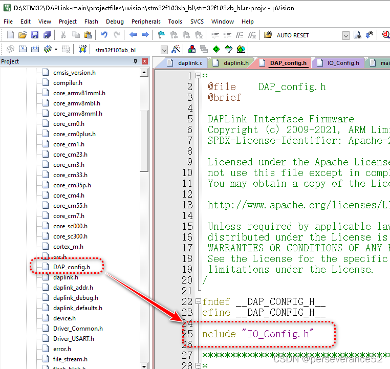
📄 DAP_config.h相关参数信息
- 📍参考信息:
https://www.armbbs.cn/forum.php?mod=viewthread&tid=99649
(1)CMSIS-DAP调试单元中使用的Cortex-M处理器参数的定义。
(2)调试单元标识字符串(供应商,产品,序列号)。
(3)调试单元通信包大小。
(4)调试访问端口支持的模式和设置(JTAG / SWD和SWO)。
(5)有关已连接目标设备(用于评估板)的可选信息。
#define         CPU_CLOCK    100000000U
数值:CPU主频时钟
描述:调试单元中使用的Cortex-M MCU的处理器时钟。该值用于计算SWD / JTAG时钟速度。

#define         IO_PORT_WRITE_CYCLES    2U
数值:I/O时钟周期, 2=default,  1=Cortex-M0+ fast I/O
描述:I / O端口写操作时钟周期(主频)。此值用于计算Cortex-M MCU在调试单元中通过I / O端口写操作生成的SWD / JTAG时钟速度。大多数Cortex-M处理器需要2个处理器周期来进行I / O端口写操作。如果调试单元使用具有高速外围设备I / O的Cortex-M0 +处理器,则可能只需要1个处理器周期。

#define         DAP_SWD    1
数值:1 = available, 0 = not available
描述:表示在调试访问端口上使用SWD调试接口。此信息由命令DAP_Info作为Capabilities的一部分返回。

#define         DAP_JTAG    1
数值:1 = available, 0 = not available
描述:表示在调试端口上使用JTAG接口。此信息由命令DAP_Info作为Capabilities的一部分返回。

#define         DAP_JTAG_DEV_CNT    8U
数值:调试访问接口上外接的设备数
描述:在连接到调试访问端口的扫描链上配置JTAG设备的最大数量。此设置会影响调试单元的RAM要求。有效范围是1 ..255。

#define         DAP_DEFAULT_PORT    1U
数值:Default JTAG/SWJ Port Mode: 1 = SWD, 2 = JTAG
描述:调试访问端口上的默认通信模式,选择端口默认模式时,用于命令DAP_Connect。

#define         DAP_DEFAULT_SWJ_CLOCK    1000000U
数值:SWJ/JTAG时钟速度。
描述:SWD和JTAG模式的调试访问端口上的默认通信速度。用于初始化默认的SWD / JTAG时钟频率。可以使用命令DAP_SWJ_Clock覆盖此默认设置。

#define         DAP_PACKET_SIZE    512U
数值:数据包大小
描述:命令和响应数据的最大包大小。此配置设置用于优化与调试器的通信性能,并且取决于USB外设。对于全速USB HID或WinUSB,典型值是64,对于高速USB HID是1024,对于高速USB WinUSB是512。

#define         DAP_PACKET_COUNT    8U
数值:支持的数据包缓冲个数,即DAP_PACKET_SIZE的个数
描述:命令和响应数据的最大包缓冲区,此配置设置用于优化与调试器的通信性能,并且取决于USB外设。对于RAM或USB缓冲区有限的设备,可以减小设置(有效范围是1 .. 255)。

#define         SWO_UART    1
数值: 1 = available, 0 = not available
貌似:指示UART串行线输出(SWO)是否可用。此信息由命令DAP_Info作为Capabilities的一部分返回。

#define         SWO_UART_MAX_BAUDRATE    10000000U
数值:SWO波特率
描述:最大SWO UART波特率。

#define         SWO_MANCHESTER    0
数值:WO Manchester:  1 = available, 0 = not available
描述:指示曼彻斯特串行线输出(SWO)跟踪可用。此信息由命令DAP_Info作为Capabilities的一部分返回。

#define         SWO_BUFFER_SIZE    4096U
数值:SWO缓冲大小
描述:两个跟踪缓冲区大小。

#define         SWO_STREAM    0
数值:SWO Streaming Trace: 1 = available, 0 = not available
描述:SWO流跟踪。

#define         TIMESTAMP_CLOCK    100000000U
数值:时间戳
描述:测试域计时器的时钟频率。计时器值通过TIMESTAMP_GET返回。

#define         TARGET_DEVICE_FIXED    0
数值:Target Device: 1 = known, 0 = unknown
调试单元连接到固定的目标设备。调试单元可以是评估板的一部分,并且始终连接到固定的已知设备。在这种情况下,将存储设备供应商和设备名称字符串,调试器或IDE可以使用该字符串来配置设备参数。
#if TARGET_DEVICE_FIXED
#define TARGET_DEVICE_VENDOR    ""              ///< String indicating the Silicon Vendor
#define TARGET_DEVICE_NAME      ""              ///< String indicating the Target Device
#endif
厂商,产品ID和串行字符串获取:
/** Get Vendor ID string.
\param str Pointer to buffer to store the string.
\return String length.
*/
__STATIC_INLINE uint8_t DAP_GetVendorString (char *str) {
  (void)str;
  return (0U);
}

/** Get Product ID string.
\param str Pointer to buffer to store the string.
\return String length.
*/
__STATIC_INLINE uint8_t DAP_GetProductString (char *str) {
  (void)str;
  return (0U);
}

/** Get Serial Number string.
\param str Pointer to buffer to store the string.
\return String length.
*/
__STATIC_INLINE uint8_t DAP_GetSerNumString (char *str) {
  (void)str;
  return (0U);
}
📚72MHz主频STM32F103编译的固件
- 🔖由于源工程630M太多不方便分享。进提供相关固件。
📢烧录再啰嗦一遍:可通过STM32 ST-LINK Utility或者STM32CubeProgrammer软件烧录stm32f103xb_bl.Hex,Bootload程序。之后,就不需要以上工具了,再通过USB(PA11,PA12)连接电脑,将出现一个64M的U盘,将stm32f103xb_stm32f103rb_if.Hex或者stm32f103xb_if.hex文件拷贝到U盘中进行升级成DAPLINK。
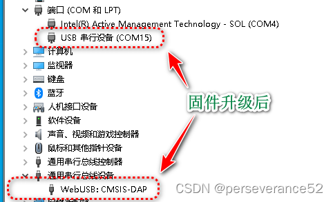
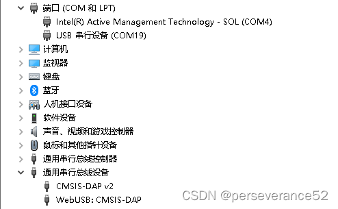
- 🌿当使用stm32f103xb_if.hex作为daplink IAP升级固件后的硬件显示:
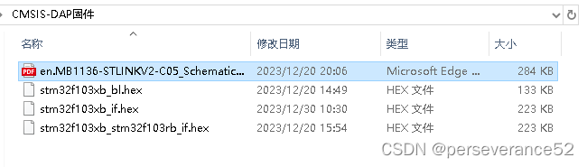
📙/包含ST-LINKV2原理图 、
stm32f103xb_bl.hex、stm32f103xb_if.hex、stm32f103xb_stm32f103rb_if.hex
链接:https://pan.baidu.com/s/1ts1Jje73dy5K0f3aVjT34A
提取码:xay4
//仅包含stm32f103xb_bl.hex、stm32f103xb_stm32f103rb_if.hex
链接:https://pan.baidu.com/s/1NDvg_HMIuZ8lElKROrOsEg
提取码:gqq2
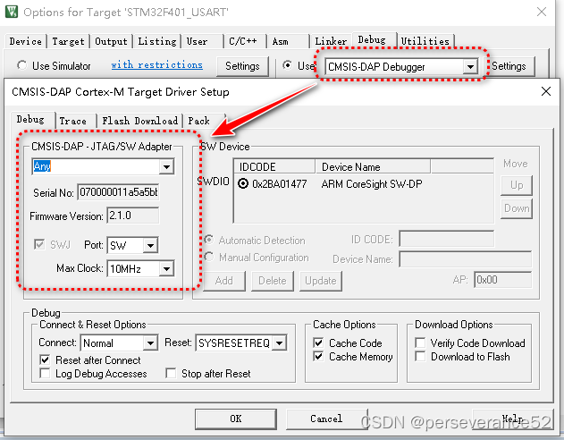
- 🔖Keil 选择DAPLINK烧录默认选项界面:
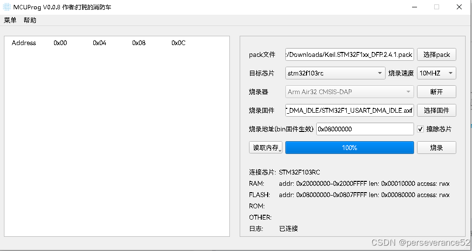
🔨CMSIS-DAP MUC烧录上位机软件推荐
- 🥕MCUProg:
https://gitee.com/Dozingfiretruck/MCUProg - 🔧该上位机软件支持烧录文件格式l类型:
.asf、.BIN、.HEX、.elf。 - 📍ARM内核.pack包下载地址:
https://www.keil.arm.com/devices/
✨使用比较简单,下载下来,无需安装,可直接使用。下载目标芯片时,需要配合该芯片的
.pack包,也就是Keil开发环境下所使用的芯片支持包。
🌼拖拽烧录方式,固件代码配置说明
- 🎉一般一个固件只能支持一个型号,例如,默认支持stm32f103型号,可以直接将hex或者bin文件拖拽到U盘实现烧录.其他系列型号的就不支持这种拖拽烧录方式,只能按照上面的
MCUProg上位机软件进行烧录。
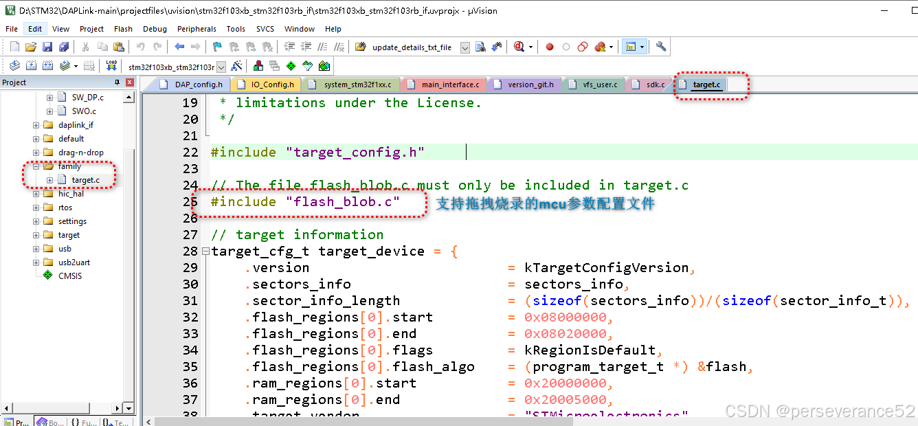
- 🌿
flash_blob.c内容:
/* Flash OS Routines (Automagically Generated)
 * Copyright (c) 2009-2019 ARM Limited
 *
 * Licensed under the Apache License, Version 2.0 (the "License");
 * you may not use this file except in compliance with the License.
 * You may obtain a copy of the License at
 *
 *     http://www.apache.org/licenses/LICENSE-2.0
 *
 * Unless required by applicable law or agreed to in writing, software
 * distributed under the License is distributed on an "AS IS" BASIS,
 * WITHOUT WARRANTIES OR CONDITIONS OF ANY KIND, either express or implied.
 * See the License for the specific language governing permissions and
 * limitations under the License.
 */

static const uint32_t STM32F103RB_flash_prog_blob[] = {
    0xE00ABE00, 0x062D780D, 0x24084068, 0xD3000040, 0x1E644058, 0x1C49D1FA, 0x2A001E52, 0x4770D1F2,
    0x4603b510, 0x4c442000, 0x48446020, 0x48446060, 0x46206060, 0xf01069c0, 0xd1080f04, 0x5055f245,
    0x60204c40, 0x60602006, 0x70fff640, 0x200060a0, 0x4601bd10, 0x69004838, 0x0080f040, 0x61104a36,
    0x47702000, 0x69004834, 0x0004f040, 0x61084932, 0x69004608, 0x0040f040, 0xe0036108, 0x20aaf64a,
    0x60084930, 0x68c0482c, 0x0f01f010, 0x482ad1f6, 0xf0206900, 0x49280004, 0x20006108, 0x46014770,
    0x69004825, 0x0002f040, 0x61104a23, 0x61414610, 0xf0406900, 0x61100040, 0xf64ae003, 0x4a2120aa,
    0x481d6010, 0xf01068c0, 0xd1f60f01, 0x6900481a, 0x0002f020, 0x61104a18, 0x47702000, 0x4603b510,
    0xf0201c48, 0xe0220101, 0x69004813, 0x0001f040, 0x61204c11, 0x80188810, 0x480fbf00, 0xf01068c0,
    0xd1fa0f01, 0x6900480c, 0x0001f020, 0x61204c0a, 0x68c04620, 0x0f14f010, 0x4620d006, 0xf04068c0,
    0x60e00014, 0xbd102001, 0x1c921c9b, 0x29001e89, 0x2000d1da, 0x0000e7f7, 0x40022000, 0x45670123,
    0xcdef89ab, 0x40003000, 0x00000000
};

/**
* List of start and size for each size of flash sector
* The size will apply to all sectors between the listed address and the next address
* in the list.
* The last pair in the list will have sectors starting at that address and ending
* at address start + size.
*/
static const sector_info_t sectors_info[] = {
    {0x08000000, 0x400},
};

static const program_target_t flash = {
    0x20000021, // Init
    0x20000053, // UnInit
    0x20000065, // EraseChip
    0x2000009f, // EraseSector
    0x200000dd, // ProgramPage
    0x0,        // Verify

    // BKPT : start of blob + 1
    // RSB  : blob start + header + rw data offset
    // RSP  : stack pointer
    {
        0x20000001,
        0x20000148,
        0x20000800
    },

    0x20000000 + 0x00000A00,  // mem buffer location
    0x20000000,               // location to write prog_blob in target RAM
    sizeof(STM32F103RB_flash_prog_blob),   // prog_blob size
    STM32F103RB_flash_prog_blob,           // address of prog_blob
    0x00000400       // ram_to_flash_bytes_to_be_written
};
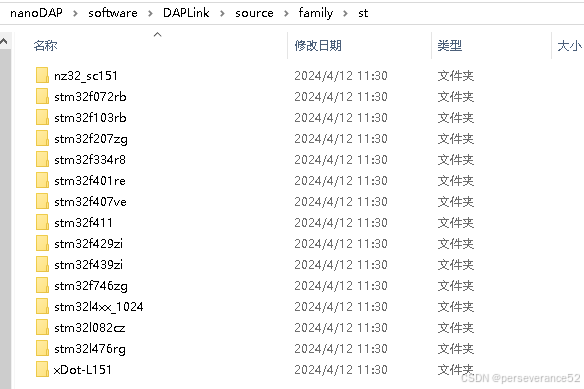
- 🧬更多支持型号的支持,可以参考
naonDAP项目https://github.com/wuxx/nanoDAP中的software\DAPLink\source\family\st:相关型号编写对应型号的内容。
📘其他说明
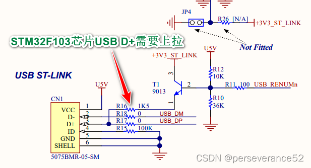
- ✨针对STM32F103制作DAPLINK,一定要注意,
USB D+需要上拉一个1.5K的电阻,否则识别不到USB接口,STM32其他较新出的芯片,不需要此上拉电阻,这一点需要注意。
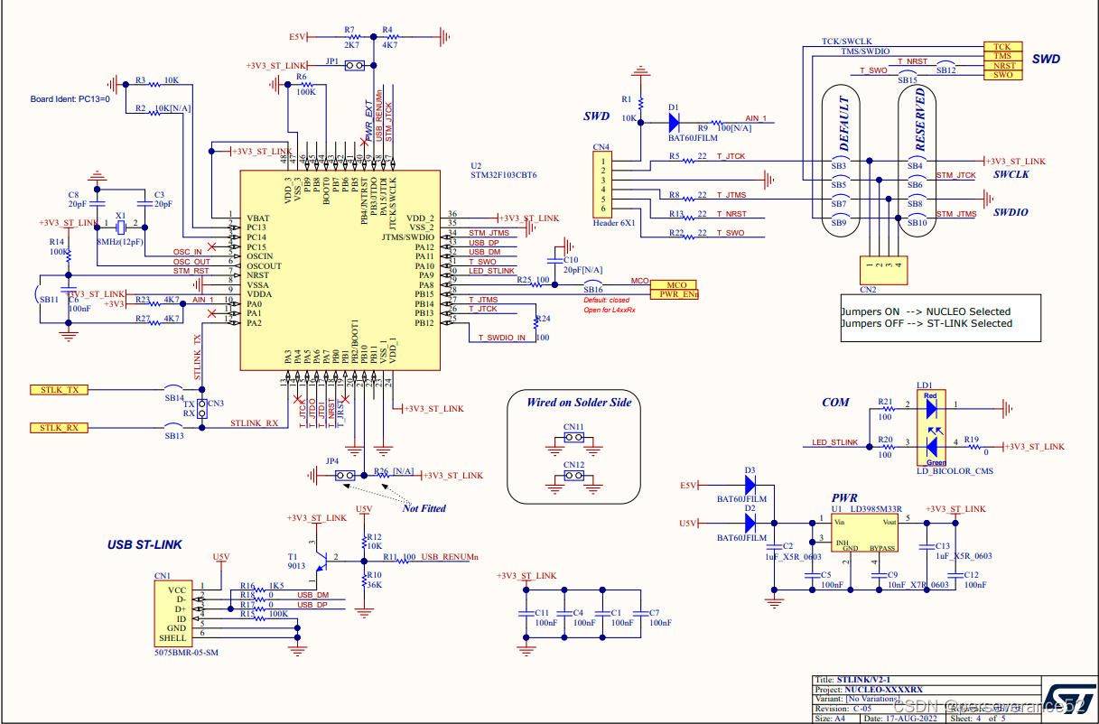
- 🍁ST-LINK原理图:


 1万+
1万+

 被折叠的 条评论
为什么被折叠?
被折叠的 条评论
为什么被折叠?
 到【灌水乐园】发言


