本实验还是在Cisco Packet Tracer里练习:
1.实验环境的搭建:
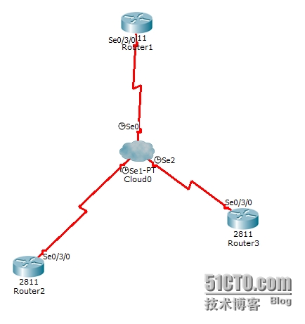
三台2811路由器,都加上HWIC-2T板卡,然后与Cloud0串口相连,如下图
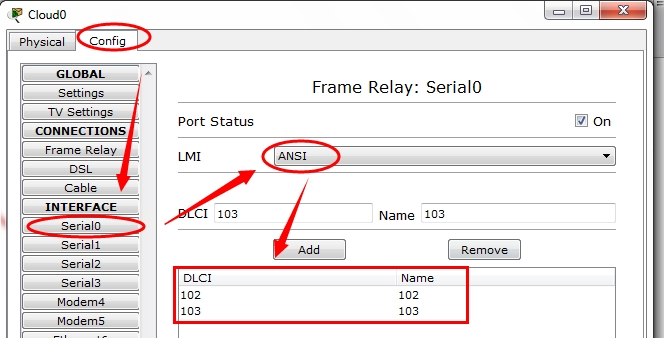
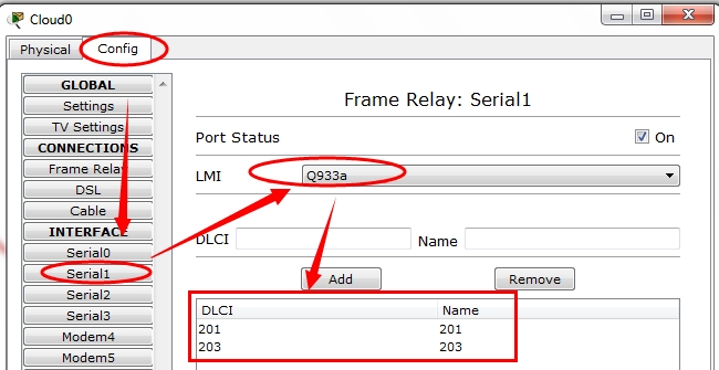
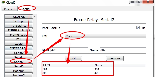
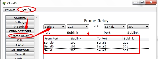
2.Cloud0 DLCI及LMI配置
Router1上配置串口s0/3/0
Router>en
Router#conf t
Enter configuration commands, one per line. End with CNTL/Z.
Router(config)#int s 0/3/0
Router(config-if)#ip add 192.168.1.1 255.255.255.0
Router(config-if)#encapsulation frame-relay
Router(config-if)#frame-relay lmi-type ansi
Router(config-if)# frame-relay map ip 192.168.1.2 102 broadcast
Router(config-if)# frame-relay map ip 192.168.1.3 103 broadcast
Router(config-if)#exit
Router(config)#exit
Router#
%SYS-5-CONFIG_I: Configured from console by console
write
Building configuration...
[OK]
Router#Router2上配置串口S0/3/0
Router>en
Router#conf t
Enter configuration commands, one per line. End with CNTL/Z.
Router(config)#int s 0/3/0
Router(config-if)#ip add 192.168.1.2 255.255.255.0
Router(config-if)#encapsulation frame-relay
Router(config-if)#frame-relay lmi-type ?
ansi
cisco
q933a
Router(config-if)#frame-relay lmi-type q933a
Router(config-if)#frame-relay map ip 192.168.1.1 201 broadcast
Router(config-if)#frame-relay map ip 192.168.1.3 203 broadcast
Router(config-if)#exit
Router(config)#exit
Router#
%SYS-5-CONFIG_I: Configured from console by console
write
Building configuration...
[OK]Router3上配置串口S0/3/0
Router>en
Router#conf t
Enter configuration commands, one per line. End with CNTL/Z.
Router(config)#int s 0/3/0
Router(config-if)#ip add 192.168.1.3 255.255.255.0
Router(config-if)#encapsulation frame-relay
Router(config-if)#frame-relay lmi-type cisco
Router(config-if)#frame-relay map ip 192.168.1.1 301 broadcast
Router(config-if)#frame-relay map ip 192.168.1.2 302 broadcast
Router(config-if)#exit
Router(config)#exit
Router#
%SYS-5-CONFIG_I: Configured from console by consoleRouter#
打开3台路由器的s 0/3/0, 即分别进入3个串口,去no shutdown。三台路由器的命令都如下:
Router>en
Router#conf t
Enter configuration commands, one per line. End with CNTL/Z.
Router(config)#int s 0/3/0
Router(config-if)#no shRouter(config-if)#
%LINK-5-CHANGED: Interface Serial0/3/0, changed state to up%LINEPROTO-5-UPDOWN: Line protocol on Interface Serial0/3/0, changed state to up
exit
Router(config)#exit
Router#
%SYS-5-CONFIG_I: Configured from console by console
wr
Building configuration...
[OK]检验
Router>en
Router#ping 192.168.1.2Type escape sequence to abort.
Sending 5, 100-byte ICMP Echos to 192.168.1.2, timeout is 2 seconds:
!!!!!
Success rate is 100 percent (5/5), round-trip min/avg/max = 2/17/51 msRouter#ping 192.168.1.3
Type escape sequence to abort.
Sending 5, 100-byte ICMP Echos to 192.168.1.3, timeout is 2 seconds:
!!!!!
Success rate is 100 percent (5/5), round-trip min/avg/max = 2/13/32 msRouter#
关于帧中继(frame-relay)的讨论,
FR全名为frame-relay(帧中继)
帧中继在X.25分组交换技术的基础上发展起来的一种快速分组交换技术,是改进的X.25的协议。帧中继是基于虚电路的,是面向连接的服务。
帧中继的特点:
帧中继协议以帧的形式转递数据信息。
帧中继传送数据使用的传输链路是逻辑连接,而不是物理连接。
采用物理层和链路层的两级结构。
在链路层完成统计复用,帧透明传输和错误检测,但不提供发现错误后的重传操作。
提供一套合理的带宽管理和防止拥塞的机制。
帧中继采用面向连接的交换技术。
帧中继的术语:
VC(virtual circuits)
虚链路(两台DTE设备之间通过帧中继网络实现的连接叫做虚链路)
PVC 永久虚链路(permanent virtual circuits)
SVC 交换虚链路(switched virtual circuits)
DLCI号(data link connection identifier)
数据链路标识符(通常是由帧中继服务提供商分配)
帧中继的PVC使用DLCI号来标示DTE设备。
帧中继DLCI仅具有本地意义。
DLCI号的范围
0---1023
DLCI号的0---15和1008---1023留作特殊用途,
服务提供商分配的DLCI范围通常为16---1007。
LMI(local management interface)
本地管理接口
是客户前端设备和帧中继交换机之间的信令标准,负责管理设备之间的连接,维护设备之间的连接状态。
Cisco路由器支持以下三种LMI类型:
Cisco
Ansi
Q933a
默认cisco设备使用的cisco。(ansi和q933a是公有的)
逆向ARP (Inverse ARP)
逆向地址解析协议
Inverse ARP的主要功能是求解每条虚电路连接的对端设备的协议地址(包括IP和IPX地址等)。如果知道了每条虚链路连接的对端设备协议地址,在本地就可以生成对端协议地址和本地DLCI的映射(MAP),从而避免手工配置地址映射。
转载于:https://blog.51cto.com/simonxu/1386209




 227
227

 被折叠的 条评论
为什么被折叠?


