


 本文介绍如何使用cartographer算法融合2D雷达与IMU进行slam建图。先说明了硬件设备,包括思岚s1激光雷达和Tobotics ROS IMU HFI - A9,接着阐述获取雷达和IMU的话题名称及frame_id的方法,然后详细讲解修改相关文件的步骤,最后完成建图并验证融合成功。
上一篇文章讲了cartographer算法手持雷达建图的参数调试,这篇进一步讲如何融合2D雷达与IMU采用cartographer算法进行slam建图。
cartographer算法手持二维激光雷达建图(不使用里程计及IMU)
https://blog.youkuaiyun.com/wangchuchua/article/details/127268037?spm=1001.2014.3001.5502
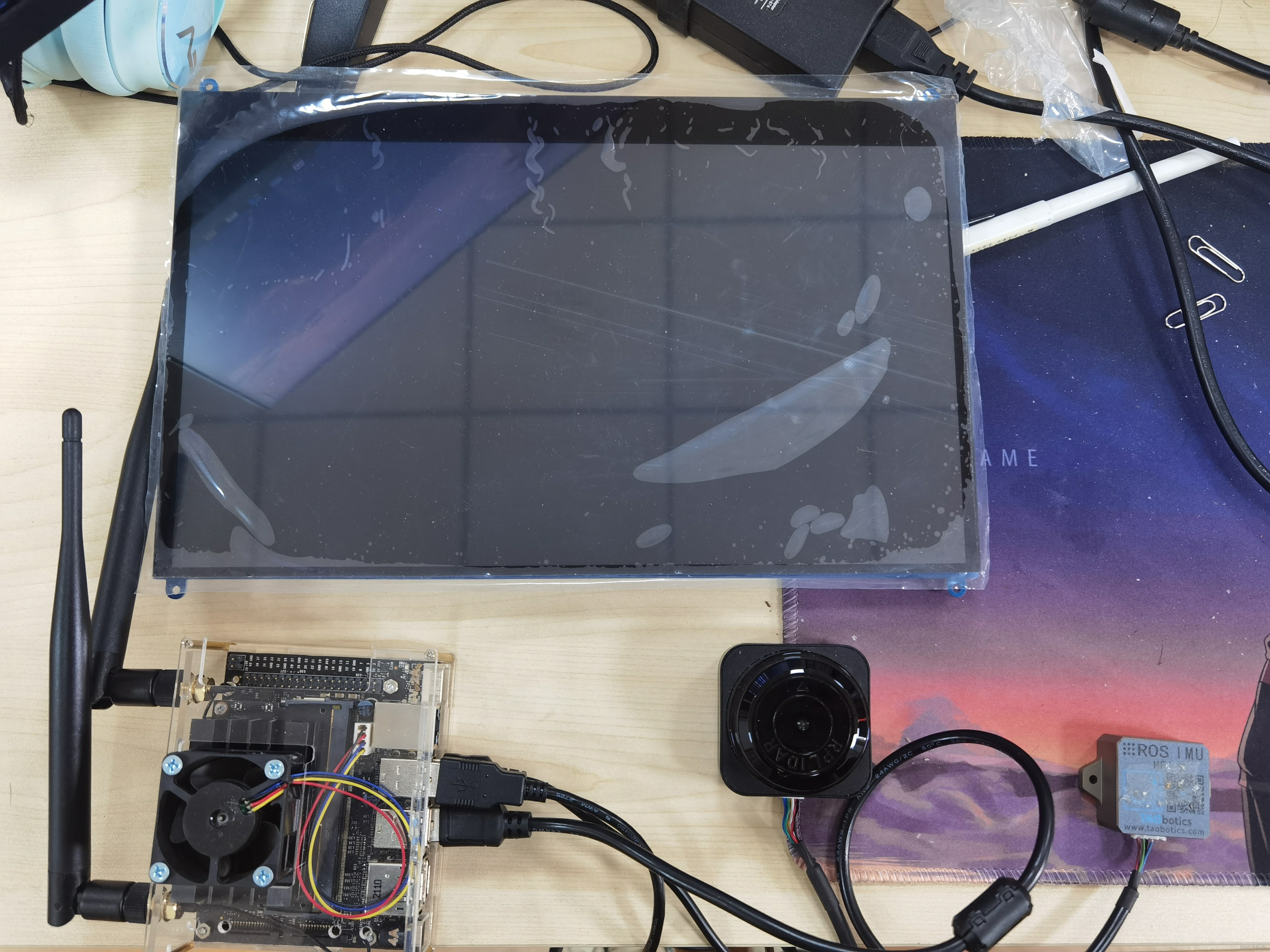
首先先说一下我的硬件设备:
思岚s1激光雷达、Tobotics ROS IMU HFI-A9。
和上一篇讲的一样在进行文件修改之前一定一定要先弄明白自己的雷达和IMU的话题名称topic_id以及frame_id,否则名称对不上肯定是会报错的。
首先启动雷达,如果有用思岚激光雷达的小伙伴可以参考这个网址。(只要可以实现点云信息的发布就好。)ROS与激光雷达入门教程-ROS中使用激光雷达(思岚S1) - 创客智造
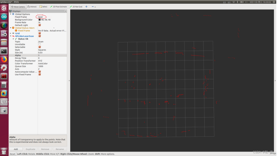
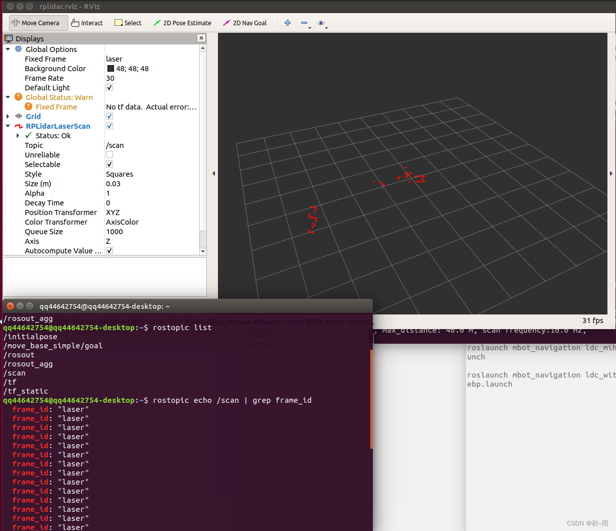
雷达的frame_id就是图中画红圈的,我的是laser。
 接下来就是查看雷达的话题名称,打开终端输入:
rostopic list可以看到雷达topic名称一般都是scan。同时还有另一种方法查询雷达的frame_id,就是在终端输入:
rostopic echo /topic | grep frame_id其中topic名称输入你雷达的话题名称就可,我的话题名称是scan所以输入:
rostopic echo /scan | grep frame_id这样就能查到话题scan的fram_id啦。通过以上操作我得知了我的雷达话题是scan、frame_id是laser。
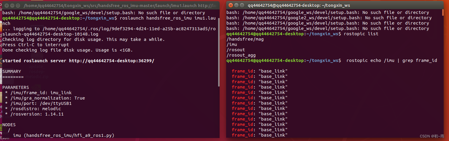
好接下来启动IMU模块,一般rosIMU是会有启动包的,启动IMU后通过rostopic查询一下IMU的话题名称,我的话题名称是/imu。知道话题名称后输入命令:rostopic echo /imu | grep frame_id查询frame-id。通过以上操作我得知了我IMU的话题名称是/imu,frame-id是base_link。知道这些后就开始正式的修改相关的文件。
首先找到~/google_ws/src/cartographer_ros/cartographer_ros/configuration_files目录下的建立一个revo_lds.lua文件,为了和手持建图的lua文件区分开,我有复制了这个文件,重命名为revo_imu.lua。修改后文件内容如下:
-- Copyright 2016 The Cartographer Authors
--
-- Licensed under the Apache License, Version 2.0 (the "License");
-- you may not use this file except in compliance with the License.
-- You may obtain a copy of the License at
--
--      http://www.apache.org/licenses/LICENSE-2.0
--
-- Unless required by applicable law or agreed to in writing, software
-- distributed under the License is distributed on an "AS IS" BASIS,
-- WITHOUT WARRANTIES OR CONDITIONS OF ANY KIND, either express or implied.
-- See the License for the specific language governing permissions and
-- limitations under the License.

include "map_builder.lua"
include "trajectory_builder.lua"

options = {
  map_builder = MAP_BUILDER,
  trajectory_builder = TRAJECTORY_BUILDER,
  map_frame = "map",
  tracking_frame = "base_link",
  published_frame = "laser",
  odom_frame = "odom",
  provide_odom_frame = true,
  publish_frame_projected_to_2d = false,
  use_pose_extrapolator = true,
  use_odometry = false,
  use_nav_sat = false,
  use_landmarks = false,
  num_laser_scans = 1,
  num_multi_echo_laser_scans = 0,
  num_subdivisions_per_laser_scan = 1,
  num_point_clouds = 0,
  lookup_transform_timeout_sec = 0.2,
  submap_publish_period_sec = 0.3,
  pose_publish_period_sec = 5e-3,
  trajectory_publish_period_sec = 30e-3,
  rangefinder_sampling_ratio = 1.,
  odometry_sampling_ratio = 1.,
  fixed_frame_pose_sampling_ratio = 1.,
  imu_sampling_ratio = 1.,
  landmarks_sampling_ratio = 1.,
}

MAP_BUILDER.use_trajectory_builder_2d = true

TRAJECTORY_BUILDER_2D.submaps.num_range_data = 35
TRAJECTORY_BUILDER_2D.min_range = 0.3
TRAJECTORY_BUILDER_2D.max_range = 8.
TRAJECTORY_BUILDER_2D.missing_data_ray_length = 1.
TRAJECTORY_BUILDER_2D.use_imu_data = true
TRAJECTORY_BUILDER_2D.use_online_correlative_scan_matching = true
TRAJECTORY_BUILDER_2D.real_time_correlative_scan_matcher.linear_search_window = 0.1
TRAJECTORY_BUILDER_2D.real_time_correlative_scan_matcher.translation_delta_cost_weight = 10.
TRAJECTORY_BUILDER_2D.real_time_correlative_scan_matcher.rotation_delta_cost_weight = 1e-1

POSE_GRAPH.optimization_problem.huber_scale = 1e2
POSE_GRAPH.optimize_every_n_nodes = 35
POSE_GRAPH.constraint_builder.min_score = 0.65

return options
主要修改的点就是一下三个地方:
tracking_frame = "base_link",#这里要与imu的frame_id名称一致
published_frame = "laser",#这里要与雷达的frame_id名称一致
TRAJECTORY_BUILDER_2D.use_imu_data = true
然后在~/google_ws/src/cartographer_ros/cartographer_ros//urdf/文件下创建一个urdf文件文件内容如下所示(我的urdf文件名称是:backpack_2d1.urdf,原本包里自带了两个urdf文件因为我要自己调整imu和雷达的位置关系就另写了一个urdf文件):这里一定要注意urdf里的link name一定要与雷达或者imu的fram_id相对应。
<!--
  Copyright 2016 The Cartographer Authors

  Licensed under the Apache License, Version 2.0 (the "License");
  you may not use this file except in compliance with the License.
  You may obtain a copy of the License at

       http://www.apache.org/licenses/LICENSE-2.0

  Unless required by applicable law or agreed to in writing, software
  distributed under the License is distributed on an "AS IS" BASIS,
  WITHOUT WARRANTIES OR CONDITIONS OF ANY KIND, either express or implied.
  See the License for the specific language governing permissions and
  limitations under the License.
-->
<robot name="mini">
  <material name="orange">
    <color rgba="1.0 0.5 0.2 1" />
  </material>
  <material name="gray">
    <color rgba="0.2 0.2 0.2 1" />
  </material>

  <link name="base_link">#与imu的fram_id对应
    <visual>
      <origin xyz="0 0 0" />
      <geometry>
        <box size="0.06 0.04 0.02" />
      </geometry>
      <material name="orange" />
    </visual>
  </link>
  <link name="laser">#与雷达的fram_id对应
    <visual>
      <origin xyz="0 0 0" />
      <geometry>
        <cylinder length="0.05" radius="0.03" />
      </geometry>
      <material name="gray" />
    </visual>
  </link>


  <joint name="imu2laser" type="fixed">
    <parent link="laser" />
    <child link="base_link" />
    <origin xyz="0 0 -0.035" />
  </joint>

</robot>
在riviz中显示是这样的,小老板们可以根据需要调整雷达和imu之间的相对位置关系。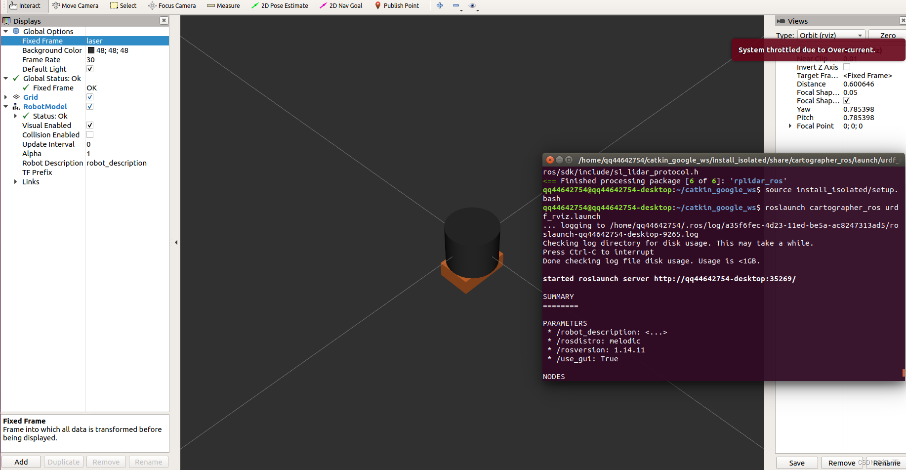
在~/google_ws/src/cartographer_ros/cartographer_ros/launch目录下建立launch文件,我的文件名称是demo_revo_sc_imu.launch。文件内容如下:
<!--
  Copyright 2016 The Cartographer Authors

  Licensed under the Apache License, Version 2.0 (the "License");
  you may not use this file except in compliance with the License.
  You may obtain a copy of the License at

       http://www.apache.org/licenses/LICENSE-2.0

  Unless required by applicable law or agreed to in writing, software
  distributed under the License is distributed on an "AS IS" BASIS,
  WITHOUT WARRANTIES OR CONDITIONS OF ANY KIND, either express or implied.
  See the License for the specific language governing permissions and
  limitations under the License.
-->

<launch>
  <param name="/use_sim_time" value="false" />

  <node name="rplidarNode"          pkg="rplidar_ros"  type="rplidarNode" output="screen">
  <param name="serial_port"         type="string" value="/dev/ttyUSB0"/>
  <param name="serial_baudrate"     type="int"    value="256000"/>
  <param name="frame_id"            type="string" value="laser"/>
  <param name="inverted"            type="bool"   value="false"/>
  <param name="angle_compensate"    type="bool"   value="true"/>
  </node>

  <node name="cartographer_node" pkg="cartographer_ros"
      type="cartographer_node" args="
          -configuration_directory $(find cartographer_ros)/configuration_files
          -configuration_basename revo_imu.lua"
      output="screen">
    <remap from="scan" to="scan" />
    <remap from="imu/data" to="imu" />#这里是你的imu的话题名称
  </node>

  <node name="cartographer_occupancy_grid_node" pkg="cartographer_ros"
      type="cartographer_occupancy_grid_node" args="-resolution 0.05" />
  <param name="robot_description" textfile="$(find cartographer_ros)/urdf/backpack_2d1.urdf" />
  <node name="robot_state_publisher" pkg="robot_state_publisher" type="robot_state_publisher" />


  <node name="rviz" pkg="rviz" type="rviz" required="true"
      args="-d $(find cartographer_ros)/configuration_files/demo_2d.rviz" />

</launch>
这个文件中包含了启动雷达节点,和cartographer建图节点,相对于上节的launch文件内容增加了
<remap from="imu/data" to="imu" />注意要用你自己imu的话题名称。
以及 urdf文件,注意要对应你的urdf文件路径。
 <param name="robot_description" textfile="$(find cartographer_ros)/urdf/backpack_2d1.urdf" />
  <node name="robot_state_publisher" pkg="robot_state_publisher" type="robot_state_publisher" />
到这里文件调整部分就完成了,可以开始启动建图了,因为上面的launch文件没有包含imu启动节点所以我这里先单独启动imu。
roslaunch handsfree_ros_imu imu1.launch
imu启动之后就可以运行 demo_revo_sc_imu.launch文件了,别忘记启动之前要catkin_make_isolated --install --use-ninja。
source install_isolated/setup.bashcatkin_make_isolated --install --use-ninjaroslaunch cartographer_ros demo_revo_sc_imu.launch
运行成功后的效果是这样的。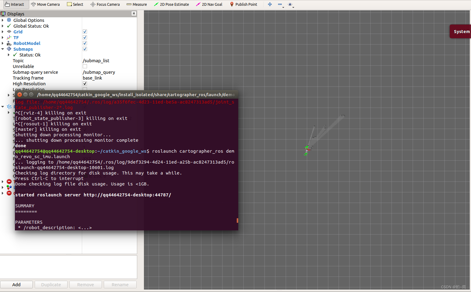
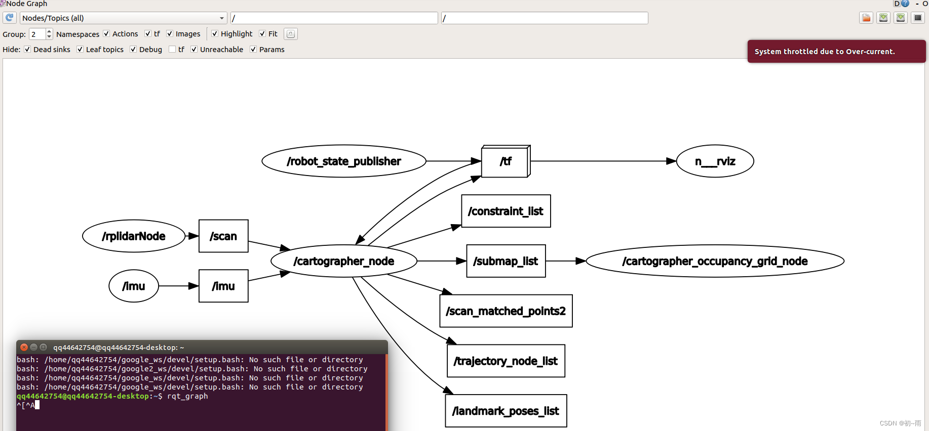
打开终端输入rqt_graph查看节点关系,我们可以看到imu和雷达信息已经输入到cartographer的节点中去说明融合成功了。
rqt_graph
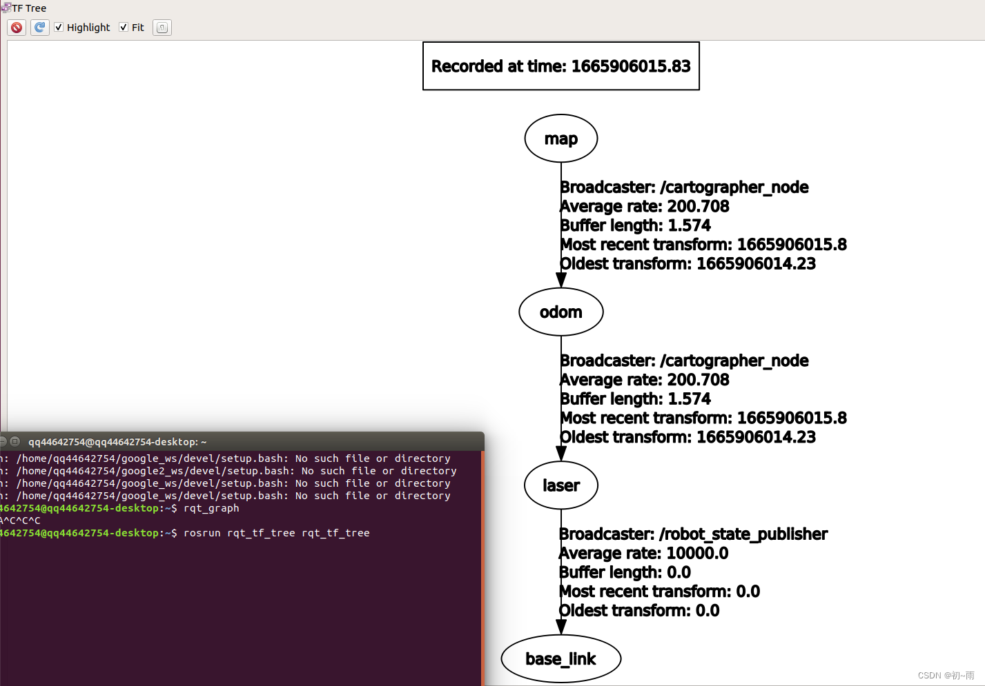
打开终端输入rosrun rqt_tf_tree rqt_tf_tree得到tf关系图:
到这里就完成了cartographer算法的雷达与IMU融合建图。希望这篇文章能够帮助到大家,祝大家生活愉快,学业顺利 (*^▽^*)。


 1126
1126

 被折叠的 条评论
为什么被折叠?
被折叠的 条评论
为什么被折叠?
 到【灌水乐园】发言


