


 本文介绍STM32微控制器中断优先级的配置方法,包括优先级分组设置、抢占优先级与响应优先级的设定及具体实现过程。
首先是中断优先级分组
NVIC_PriorityGroupConfig(NVIC_PriorityGroup_2);
//########################下面是内容########################
void NVIC_PriorityGroupConfig(uint32_t NVIC_PriorityGroup)
{
  /* Check the parameters */
  assert_param(IS_NVIC_PRIORITY_GROUP(NVIC_PriorityGroup));

  /* Set the PRIGROUP[10:8] bits according to NVIC_PriorityGroup value */
  SCB->AIRCR = AIRCR_VECTKEY_MASK | NVIC_PriorityGroup;
}
assert_param查看参数是否有效;
NVIC_PriorityGroup可选范围如下:
#define NVIC_PriorityGroup_0         ((uint32_t)0x700) /*!< 0 bits for pre-emption priority
                                                            4 bits for subpriority */
#define NVIC_PriorityGroup_1         ((uint32_t)0x600) /*!< 1 bits for pre-emption priority
                                                            3 bits for subpriority */
#define NVIC_PriorityGroup_2         ((uint32_t)0x500) /*!< 2 bits for pre-emption priority
                                                            2 bits for subpriority */
#define NVIC_PriorityGroup_3         ((uint32_t)0x400) /*!< 3 bits for pre-emption priority
                                                            1 bits for subpriority */
#define NVIC_PriorityGroup_4         ((uint32_t)0x300) /*!< 4 bits for pre-emption priority
                                                            0 bits for subpriority */
/*############################展开#################################*/
NVIC_PriorityGroup_0   0111 0000 0000
NVIC_PriorityGroup_1   0110 0000 0000
NVIC_PriorityGroup_2   0101 0000 0000
NVIC_PriorityGroup_3   0100 0000 0000
NVIC_PriorityGroup_4   0011 0000 0000
AIRCR_VECTKEY_MASK定义如下:
#define AIRCR_VECTKEY_MASK ((uint32_t)0x05FA0000)
相与后送到SCB->AIRCR中,SCB定义如下:
#define SCB                 ((SCB_Type *)           SCB_BASE)
#############################################################
#define SCB_BASE            (SCS_BASE +  0x0D00)
#############################################################
#define SCS_BASE            (0xE000E000)
所以SCB首地址是0xE000 ED00;SCB是个结构体指针,结构体定义如下:
typedef struct
{
  __I  uint32_t CPUID;                        /*!< Offset: 0x00  CPU ID Base Register                                  */
  __IO uint32_t ICSR;                         /*!< Offset: 0x04  Interrupt Control State Register                      */
  __IO uint32_t VTOR;                         /*!< Offset: 0x08  Vector Table Offset Register                          */
  __IO uint32_t AIRCR;                        /*!< Offset: 0x0C  Application Interrupt / Reset Control Register        */
  __IO uint32_t SCR;                          /*!< Offset: 0x10  System Control Register                               */
  __IO uint32_t CCR;                          /*!< Offset: 0x14  Configuration Control Register                        */
  __IO uint8_t  SHP[12];                      /*!< Offset: 0x18  System Handlers Priority Registers (4-7, 8-11, 12-15) */
  __IO uint32_t SHCSR;                        /*!< Offset: 0x24  System Handler Control and State Register             */
  __IO uint32_t CFSR;                         /*!< Offset: 0x28  Configurable Fault Status Register                    */
  __IO uint32_t HFSR;                         /*!< Offset: 0x2C  Hard Fault Status Register                            */
  __IO uint32_t DFSR;                         /*!< Offset: 0x30  Debug Fault Status Register                           */
  __IO uint32_t MMFAR;                        /*!< Offset: 0x34  Mem Manage Address Register                           */
  __IO uint32_t BFAR;                         /*!< Offset: 0x38  Bus Fault Address Register                            */
  __IO uint32_t AFSR;                         /*!< Offset: 0x3C  Auxiliary Fault Status Register                       */
  __I  uint32_t PFR[2];                       /*!< Offset: 0x40  Processor Feature Register                            */
  __I  uint32_t DFR;                          /*!< Offset: 0x48  Debug Feature Register                                */
  __I  uint32_t ADR;                          /*!< Offset: 0x4C  Auxiliary Feature Register                            */
  __I  uint32_t MMFR[4];                      /*!< Offset: 0x50  Memory Model Feature Register                         */
  __I  uint32_t ISAR[5];                      /*!< Offset: 0x60  ISA Feature Register                                  */
} SCB_Type;
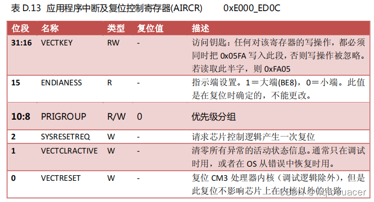
其中AIRCR为32位,10:8位设置优先级分组,如下图(Cortex-M3权威指南P285),31:16位必须为0xFA05,所以AIRCR_VECTKEY_MASK值为((uint32_t)0x05FA0000)。
所以选第二组的话此时SCB->AIRCR值为:0x05FA 0500
设置完中断优先级分组后,需要去设置抢占优先级、响应优先级、外部中断通道和使能,如下:
    NVIC_InitTypeDef NVIC_InitStructure;
    NVIC_InitStructure.NVIC_IRQChannel = EXTI0_IRQn;
  	NVIC_InitStructure.NVIC_IRQChannelPreemptionPriority = 0x02;
  	NVIC_InitStructure.NVIC_IRQChannelSubPriority = 0x03;
  	NVIC_InitStructure.NVIC_IRQChannelCmd = ENABLE;
  	NVIC_Init(&NVIC_InitStructure);
NVIC_InitStructure结构体类型如下,第一个成员用来设置中断向量表通道,这里设置的是外部中断0,第四个成员是用来使能的。
typedef struct
{
  uint8_t NVIC_IRQChannel;
  uint8_t NVIC_IRQChannelPreemptionPriority;
  uint8_t NVIC_IRQChannelSubPriority;
  FunctionalState NVIC_IRQChannelCmd;
} NVIC_InitTypeDef;
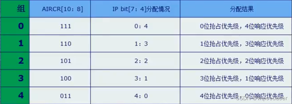
第二三个成员用来设置抢占优先级和响应优先级,对应关系如下。
NVIC_Init(&NVIC_InitStructure); 函数内容如下:
void NVIC_Init(NVIC_InitTypeDef* NVIC_InitStruct)
{
  uint32_t tmppriority = 0x00, tmppre = 0x00, tmpsub = 0x0F;
  if (NVIC_InitStruct->NVIC_IRQChannelCmd != DISABLE)
  {
    tmppriority = (0x700 - ((SCB->AIRCR) & (uint32_t)0x700))>> 0x08;
    tmppre = (0x4 - tmppriority);
    tmpsub = tmpsub >> tmppriority;
函数目的是将设置好的通道、优先级、使能等信息放到相应的地方
首先判断是否使能,使能了就用0x700给SCB->AIRCR的其他位清零,只保留AIRCR[10:8]位,然后用0111-0101=0010后右移8位,变成0010,然后赋值给 tmppriority(它的值在0~4之间变化,因为AIRCR[10:8]这三位取值范围是3~7),假设取第1组AIRCR[10:8]=110=6,tmppriority=1。如下表:
|
优先级分组 | AIRCR[10:8] |
IP[7:4] 抢占:响应 | tmppriority | tmppre | tmpsub |
| 0 | 111=7 | 0:4 | 0 | 4 | 0000 1111 |
| 1 | 110=6 | 1:3 | 1 | 3 | 0000 0111 |
| 2 | 101=5 | 2:2 | 2 | 2 | 0000 0011 |
| 3 | 100=4 | 3:1 | 3 | 1 | 0000 0001 |
| 4 | 011=3 | 4:0 | 4 | 0 | 0000 0000 |
接下来将抢占优先级和响应优先级的信息赋值给tmppriority,即:
先把抢占优先级NVIC_IRQChannelPreemptionPriority的取值(假设为1)左移tmppre(3位)位,然后赋值给tmppriority=1000,再把响应优先级NVIC_IRQChannelSubPriority的取值(假设为010)与tmpsub相与(目的是对其余的无效位清零保留有效位)后放进tmppriority=1010,这时候tmppriority就携带了抢占优先级和响应优先级的信息。
    tmppriority = (uint32_t)NVIC_InitStruct->NVIC_IRQChannelPreemptionPriority << tmppre;
    tmppriority |=  NVIC_InitStruct->NVIC_IRQChannelSubPriority & tmpsub;
    tmppriority = tmppriority << 0x04;
    NVIC->IP[NVIC_InitStruct->NVIC_IRQChannel] = tmppriority;
    NVIC->ISER[NVIC_InitStruct->NVIC_IRQChannel >> 0x05] =
      (uint32_t)0x01 << (NVIC_InitStruct->NVIC_IRQChannel & (uint8_t)0x1F);
  }
  else
  {
    NVIC->ICER[NVIC_InitStruct->NVIC_IRQChannel >> 0x05] =
      (uint32_t)0x01 << (NVIC_InitStruct->NVIC_IRQChannel & (uint8_t)0x1F);
  }
}
将tmppriority左移4位给相应的IP[]:1010 0000,因为IP[]是高4位有效的,同时将使能信息给ISER。
就不详细解释了。下面是60个中断向量。
  WWDG_IRQn                   = 0,      /*!< Window WatchDog Interrupt                            */
  PVD_IRQn                    = 1,      /*!< PVD through EXTI Line detection Interrupt            */
  TAMPER_IRQn                 = 2,      /*!< Tamper Interrupt                                     */
  RTC_IRQn                    = 3,      /*!< RTC global Interrupt                                 */
  FLASH_IRQn                  = 4,      /*!< FLASH global Interrupt                               */
  RCC_IRQn                    = 5,      /*!< RCC global Interrupt                                 */
  EXTI0_IRQn                  = 6,      /*!< EXTI Line0 Interrupt                                 */
  EXTI1_IRQn                  = 7,      /*!< EXTI Line1 Interrupt                                 */
  EXTI2_IRQn                  = 8,      /*!< EXTI Line2 Interrupt                                 */
  EXTI3_IRQn                  = 9,      /*!< EXTI Line3 Interrupt                                 */
  EXTI4_IRQn                  = 10,     /*!< EXTI Line4 Interrupt                                 */
  DMA1_Channel1_IRQn          = 11,     /*!< DMA1 Channel 1 global Interrupt                      */
  DMA1_Channel2_IRQn          = 12,     /*!< DMA1 Channel 2 global Interrupt                      */
  DMA1_Channel3_IRQn          = 13,     /*!< DMA1 Channel 3 global Interrupt                      */
  DMA1_Channel4_IRQn          = 14,     /*!< DMA1 Channel 4 global Interrupt                      */
  DMA1_Channel5_IRQn          = 15,     /*!< DMA1 Channel 5 global Interrupt                      */
  DMA1_Channel6_IRQn          = 16,     /*!< DMA1 Channel 6 global Interrupt                      */
  DMA1_Channel7_IRQn          = 17,     /*!< DMA1 Channel 7 global Interrupt                      */
  ADC1_2_IRQn                 = 18,     /*!< ADC1 and ADC2 global Interrupt                       */
  USB_HP_CAN1_TX_IRQn         = 19,     /*!< USB Device High Priority or CAN1 TX Interrupts       */
  USB_LP_CAN1_RX0_IRQn        = 20,     /*!< USB Device Low Priority or CAN1 RX0 Interrupts       */
  CAN1_RX1_IRQn               = 21,     /*!< CAN1 RX1 Interrupt                                   */
  CAN1_SCE_IRQn               = 22,     /*!< CAN1 SCE Interrupt                                   */
  EXTI9_5_IRQn                = 23,     /*!< External Line[9:5] Interrupts                        */
  TIM1_BRK_IRQn               = 24,     /*!< TIM1 Break Interrupt                                 */
  TIM1_UP_IRQn                = 25,     /*!< TIM1 Update Interrupt                                */
  TIM1_TRG_COM_IRQn           = 26,     /*!< TIM1 Trigger and Commutation Interrupt               */
  TIM1_CC_IRQn                = 27,     /*!< TIM1 Capture Compare Interrupt                       */
  TIM2_IRQn                   = 28,     /*!< TIM2 global Interrupt                                */
  TIM3_IRQn                   = 29,     /*!< TIM3 global Interrupt                                */
  TIM4_IRQn                   = 30,     /*!< TIM4 global Interrupt                                */
  I2C1_EV_IRQn                = 31,     /*!< I2C1 Event Interrupt                                 */
  I2C1_ER_IRQn                = 32,     /*!< I2C1 Error Interrupt                                 */
  I2C2_EV_IRQn                = 33,     /*!< I2C2 Event Interrupt                                 */
  I2C2_ER_IRQn                = 34,     /*!< I2C2 Error Interrupt                                 */
  SPI1_IRQn                   = 35,     /*!< SPI1 global Interrupt                                */
  SPI2_IRQn                   = 36,     /*!< SPI2 global Interrupt                                */
  USART1_IRQn                 = 37,     /*!< USART1 global Interrupt                              */
  USART2_IRQn                 = 38,     /*!< USART2 global Interrupt                              */
  USART3_IRQn                 = 39,     /*!< USART3 global Interrupt                              */
  EXTI15_10_IRQn              = 40,     /*!< External Line[15:10] Interrupts                      */
  RTCAlarm_IRQn               = 41,     /*!< RTC Alarm through EXTI Line Interrupt                */
  USBWakeUp_IRQn              = 42,     /*!< USB Device WakeUp from suspend through EXTI Line Interrupt */
  TIM8_BRK_IRQn               = 43,     /*!< TIM8 Break Interrupt                                 */
  TIM8_UP_IRQn                = 44,     /*!< TIM8 Update Interrupt                                */
  TIM8_TRG_COM_IRQn           = 45,     /*!< TIM8 Trigger and Commutation Interrupt               */
  TIM8_CC_IRQn                = 46,     /*!< TIM8 Capture Compare Interrupt                       */
  ADC3_IRQn                   = 47,     /*!< ADC3 global Interrupt                                */
  FSMC_IRQn                   = 48,     /*!< FSMC global Interrupt                                */
  SDIO_IRQn                   = 49,     /*!< SDIO global Interrupt                                */
  TIM5_IRQn                   = 50,     /*!< TIM5 global Interrupt                                */
  SPI3_IRQn                   = 51,     /*!< SPI3 global Interrupt                                */
  UART4_IRQn                  = 52,     /*!< UART4 global Interrupt                               */
  UART5_IRQn                  = 53,     /*!< UART5 global Interrupt                               */
  TIM6_IRQn                   = 54,     /*!< TIM6 global Interrupt                                */
  TIM7_IRQn                   = 55,     /*!< TIM7 global Interrupt                                */
  DMA2_Channel1_IRQn          = 56,     /*!< DMA2 Channel 1 global Interrupt                      */
  DMA2_Channel2_IRQn          = 57,     /*!< DMA2 Channel 2 global Interrupt                      */
  DMA2_Channel3_IRQn          = 58,     /*!< DMA2 Channel 3 global Interrupt                      */
  DMA2_Channel4_5_IRQn        = 59      /*!< DMA2 Channel 4 and Channel 5 global Interrupt        */


 1347
1347


 到【灌水乐园】发言


