


2024年9月30日上午开始写:
以前一直玩Arduino,后来开始入手STM32,但是被相对复杂的编程搞的很不爽(毕竟50+了),后来发现用Arduino可以开发STM32,深感兴奋,就开始从基本的输入输出来研究。这个过程中,发现网上很多内容写的很简单,有的还是用的以下环境https://dan.drown.org/stm32duino/package_STM32duino_index.json
我经过对比发现还是官方的以下环境最好用https://github.com/stm32duino/BoardManagerFiles/raw/main/package_stmicroelectronics_index.json
它支持全系列STM芯片,我测试了F103C8T6、F103ZET6、F407ZET6、F407ZGT6、F429IGT6几乎所有芯片都提供了“variants”文件夹,大部分都添加到“工具”菜单里了,没有在菜单里的,都有对应的“variants”文件夹,并提供了如何添加的方法。详见以下链接https://github.com/stm32duino/Arduino_Core_STM32/wiki/Add-a-new-variant-%28board%29
修改完成之后,在Arduino IDE里还是看不到对应的板子,参考以下链接:
对于Windows这时退出IDE,找到如下文件夹:
C:\Users\xxxxxxxx\AppData\Roaming\arduino-ide
把他删除掉,再进入IDE,发现以前所有的设置都清空了,添加的板子已经可以使用了。
下面是三种操作系统的对应文件夹。
Windows:
C:\Users\<user name>\AppData\Roaming\arduino-ide\
Linux:
~/.config/arduino-ide/
macOS:
~/Library/Application Support/arduino-ide/
我就是根据这个教程,一步步完成了STM32F429IGT6的添加,并测试了程序,以下的代码都是基于STM32F429IGT6的,并且都测试成功。
有时候GitHUB访问会非常慢,或总是打不开页面,下面把如何添加的步骤和最后解决不显示添加板子的方法贴出来:
++++++++++++++++++++++以下为添加一种新板子的方法+++++++++++++++++++++++++++++++++++++++++++
Frederic Pillon edited this page on May 28 · 42 revisions
What is a variant?
It is described by Arduino here

A core variant folder is an additional folder that is compiled together with the core and allows platform developers to easily add specific configurations.

Variants must be placed inside the variants folder in the current architecture.

Since STM32 core release 2.0.0 variants folder contains one folder for each STM32 MCU family.

Variants folders
Each MCU family has several MCU references. Each subfolder name can contain one or more mcu reference(s).

STM32G0xx family example
MCU name are factorized to avoid long path names, for example:

G0B1R(B-C-E)T_G0C1R(C-E)T is for G0B1RBT, G0B1RCT, G0B1RET, G0C1RCT and G0C1RET.

All generic variants are now automatically generated in the variant folder thanks the STM32_open_pin_data repository which provides all the information required for the pin configuration of products based on STM32 MCU.

This means that the generic STM32 MCU files required for a variant are generated inside each MCU folder. Only the linker script is not automatically generated. Note that the default system clock configuration is empty by default. So the default clock at reset will be used.

Generated variant files
Warning

Below files are automatically generated so do not modify them. Only the generic_clock.c can be modified to add default system clock configuration and so will not be overwritten.

board_entry.txt: contains generic variant declaration to ease board addition in the boards.txt file. See Arduino boards.txt specification.
generic_clock.c: contains the default system clock configuration: WEAK void SystemClock_Config(void)
PinNamesVar.h: contains specific PinName definitions of the MCU
PeripheralPins.c: contains list of available PinName per peripheral.
variant_generic.cpp: contains Digital PinName array and Analog (`Ax) [pin number] array
variant_generic.h: contains all definition required by the variant: STM32 [pin number] definitions, peripheral pins for default instances: Serial, I2C, SPI, Tone, Servo, ...
Tip

The example of all the steps below are available in this PR: Add generic G0B1R(B-C-E)T, G0C1R(C-E)T and Nucleo-G0B1RE

Define a new generic variant
Before adding a specific board, it is a good practice to add the generic entry of the STM32 MCU as it is possible to use it with the specific board.

Note

A folder name can reference several MCU references so several boards entry could be added. Not only the one of the specific board.

1 - Find the MCU folder
Go to the variants folder of the STM32 core (See Where are sources).

Example: To add variant for the Nucleo-G0B1RE search for the folder name including G0B1RET reference in the STM32G0xx subfolder of the variants folder. In this case:

G0B1R(B-C-E)T_G0C1R(C-E)T

Several files are present as stated here. It misses only the default linker script named ldscript.ld.

2 - Add the default linker script
It could be generated thanks STM32CubeMX.

Open STM32CubeMX then create a New Project and select the targeted MCU. In this example the STM32G0B1RET:
Create new CubeMX project...
Configure the project thanks the Project Manager tab:
Set a project name
Set a project location
Select the IDE: STM32CubeIDE
Configure the project...
Generate the code by clicking on _ Generate Code_ button and open the folder
Generate the project...
Copy the STM32YYxxxxxx_FLASH.ld generated by STM32CubeMX in the variant folder and rename it: ldscript.ld
Example for the Nucleo-G0B1RE: STM32G0B1RETX_FLASH.ld

In order to have a common linker script for all MCU the RAM and FLASH definitions have to be updated. As the linker script is preprocessed it is possible to use some definitions based on board entry and defined by the platform.txt.

-Wl,--defsym=LD_FLASH_OFFSET={build.flash_offset} -Wl,--defsym=LD_MAX_SIZE={upload.maximum_size} -Wl,--defsym=LD_MAX_DATA_SIZE={upload.maximum_data_size}
LD_FLASH_OFFSET: Flash base offset mainly used when a custom bootloader is used. Default set to 0.
LD_MAX_DATA_SIZE: RAM size
LD_MAX_SIZE: Flash size
Edit the ldscript.ld file accordingly:

 /* Memories definition */
 MEMORY
 {
-  RAM    (xrw)    : ORIGIN = 0x20000000,   LENGTH = 144K
-  FLASH    (rx)    : ORIGIN = 0x8000000,   LENGTH = 512K
+  RAM    (xrw)    : ORIGIN = 0x20000000,   LENGTH = LD_MAX_DATA_SIZE
+  FLASH    (rx)    : ORIGIN = 0x8000000 + LD_FLASH_OFFSET, LENGTH = LD_MAX_SIZE - LD_FLASH_OFFSET
 }
3 - Generic System Clock configuration
generic_clock.c contains the default system clock configuration which is empty by default. So the default clock at reset will be used as stated by the warning:

WEAK void SystemClock_Config(void)
{
  /* SystemClock_Config can be generated by STM32CubeMX */
#warning "SystemClock_Config() is empty. Default clock at reset is used."
}
Important

For generic board the internal clock is used: HSI.

STM32CubeMX is also used to generate it.

Go to Pinout tab, enable the desired peripherals which require specific clock configuration (not needed for peripherals clocked by HCLKx, or APBx clock): SDIO, USB, ... In this example only USB needs to be enabled as other peripherals default clock are correct by default.
Pinout configuration...
Configure the clock:
Set PLL Source Mux to HSI.
Try to set the CPU clock and HCLK to the maximum frequencies, STM32CubeMX will automatically configure the clock tree and resolve conflict if any. Sometimes due to some constraints (ex: USB) maximum frequency is not reachable.
Generate the code by clicking on _ Generate Code_ button and open the folder
Generate the project...
In the generic_clock.c replace the body of the SystemClock_Config(void) by the one generated in src/main.c of the generated project.
Example
Tip

Pay attention to the default value of HAL RCC structures. CubeMx set it to 0 but it produces warning. Simply remove the 0 like this:

-  RCC_OscInitTypeDef RCC_OscInitStruct = {0};
-  RCC_ClkInitTypeDef RCC_ClkInitStruct = {0};
+  RCC_OscInitTypeDef RCC_OscInitStruct = {};
+  RCC_ClkInitTypeDef RCC_ClkInitStruct = {};
4 - Declare the variant
It is still to add the menu and add relevant information (Flash and SRAM sizes, ...)

Tip

See Arduino boards.txt specification for further options.

Edit boards.txt file, then:

Find the menu part where to add the generic entry. In this example the GenG0 menu.
Copy all the boards entry from the board_entry.txt file to this section. Pay attention to alphabetical order.
Check if the build.product_line= is correct and match the STM32YYXXxx MCU version.
Check the upload.maximum_size= and upload.maximum_data_size=
Example
5 - Add new reference to the README.md
Finally, all the new reference have to be added in the README.md

Example
6 - Restart
Restart Arduino IDE and try one of the new entry with the CheckVariant example.

++++++++++++++++++++++++++++++以下为解决不显示新添加板子的方法+++++++++++++++++++++++++++++
Important

An issue with the Arduino IDE 2.x prevents the board to appears in the menu. Follow this workaround to get it working:
https://github.com/arduino/arduino-ide/issues/1030#issuecomment-1152005617

Thanks for the report @KurtE. This caching issue also affects the Tools > Programmer menu contents: #591

I'll share the workaround:

Select File > Quit from the Arduino IDE menus if it is running.
Delete the "User data" folder:
Windows:
C:\Users\<user name>\AppData\Roaming\arduino-ide\
Linux:
~/.config/arduino-ide/
macOS:
~/Library/Application Support/arduino-ide/
Start the Arduino IDE.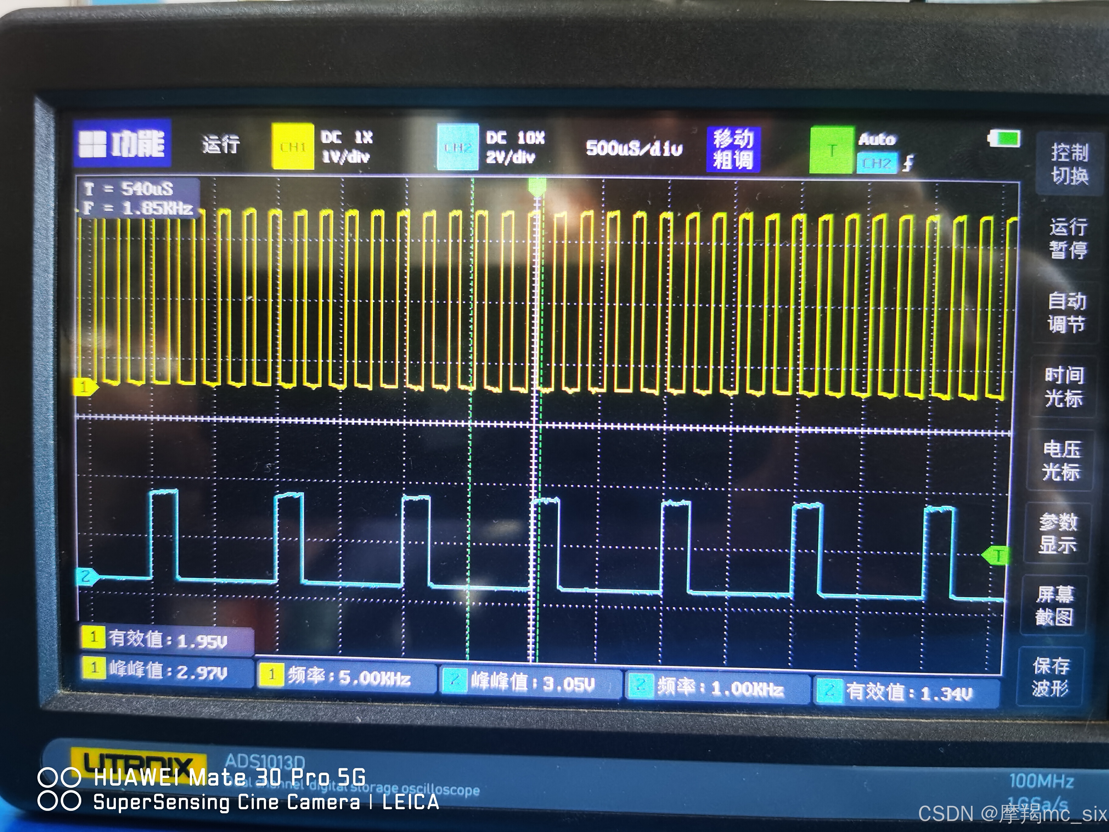
The custom board options menus should now reflect any changes that were made to boards.txt.在研究PWM的时候找了很多教程,有些还收费(非常鄙视之),交了钱发现就是用的PWMWrite(),但是官方环境没有这个函数。经过不懈努力终于搞明白了以下三个函数的作用。
analogWriteFrequency(5000);  //设置analogWrite引脚输出的PWM频率
analogWriteResolution(8);  //设置analogWrite引脚输出的PWM精度,8-16位
analogWrite(PWM_IO1, j);  //analogWrite引脚输出
analogWriteFrequency(1000);  //设置analogWrite引脚输出的PWM频率
analogWriteResolution(9);  //设置analogWrite引脚输出的PWM精度,8-16位
analogWrite(PWM_IO2, j);  //analogWrite引脚输出


//频率和精度设置必须放在loop里,如放在setup里loop执行时会按照setup里最后一次设置的执行
数字输入输出是通过外接LED来验证的;
模拟输入是通过串口打印(同时验证了串口设置)来验证的;
PWM输出是通过示波器来验证的,两个管脚设置不同的频率和精度;
单键中断控制翻转,因429核心板无板载按键(编译通过),是通过F407核心板(有板载按键)验证的;
下面是一些总结:
/*管脚输入输出定义
pinMode()
OUTPUT -基本数字输出:当引脚为高电平时,电压保持在 +3.3v (Vcc),当引脚为低电平时,电压被拉至地。
OUTPUT_OPEN_DRAIN -在开漏模式下,引脚通过接受流向地的电流来指示“低”,通过提供更高的阻抗来指示“高”。
一个示例用途是将引脚连接到总线线路(由单独的电源通过大电阻器上拉至正电压)。当引脚为高电平时,流向地的电流不多,线路保持正电压;当引脚为低电平时,总线“漏极”至地,少量电流不断从外部电源流过大电阻器。在此模式下,实际上没有电流来自引脚。
INPUT -基本数字输入。对引脚电压进行采样;当它接近 3.3V (Vcc) 时,引脚状态为高电平,当它接近 0V (接地)时,它为低电平。如果没有外部电路将引脚电压拉高或拉低,它将倾向于随机振荡并且对噪声非常敏感(例如,穿过引脚的呼吸空气可能会导致状态翻转)。
INPUT_ANALOG -这是一种特殊模式,用于 pin 用于模拟(非数字)读取。允许对引脚上的电压执行 ADC 转换。
INPUT_PULLUP -在此模式下,引脚状态的报告方式与 INPUT 相同,但引脚电压被轻轻地“拉高”至 +3.3v。这意味着除非外部设备专门将引脚拉至地,否则状态将为高电平,在这种情况下,“温和”上拉不会影响输入的状态。
INPUT_PULLDOWN -在此模式下,引脚状态的报告方式与 INPUT 相同,但引脚电压被轻轻地“拉低”至 0v。这意味着除非外部设备专门将引脚拉高至 3.3v,否则状态将为低电平,在这种情况下,“温和”下拉不会影响输入的状态。
INPUT_FLOATING -INPUT 的同义词。
*/

//硬串口定义
HardwareSerial Serial1(PA10, PA9);  //将串口1的管脚指定到PA10(RX),PA9(TX)引脚上

//PWM输出定义,这三个得连着写,并且写在  loop  函数里;
analogWriteFrequency(5000);  //设置analogWrite引脚输出的PWM频率
analogWriteResolution(9);  //设置analogWrite引脚输出的PWM精度,8-16位
analogWrite(PWM_IO1, j);  //analogWrite引脚输出

//ADC定义
analogReadResolution(10);  //设置ADC采样的精度,8-16位
Serial1.print("Resolution(10):");
Serial1.println(analogRead(ADC_IO1));  //读取ADC

/*中断定义及中断处理程序
attachInterrupt(digitalPinToInterrupt(int_1), ledflash, FALLING);   //创建中断
RISING -当引脚从 LOW 转换为 HIGH 时触发中断。
FALLING -当引脚从 HIGH 转换为 LOW 时触发中断。
CHANGE -当引脚从 LOW 转换为 HIGH 或 HIGH 转换为 LOW 时(即当引脚发生变化时),触发中断。
*/
//中断处理程序及按键消除抖动,单键循环改变状态
int trig_time=0;
void ledflash(){
  if (millis()-trig_time>200 & a==0){
    trig_time=millis();
    a=1;
  }
  else if (millis()-trig_time>200 & a==1){
    trig_time=millis();
    a=0;
  }
}
2024年9月30日下午更新:
增加了DHT11和DS18B20测温湿度和温度的代码。
DHT11的代码抄自Arduino标准库“dht-sensors-non-blocking”的示例,可以从库管理里面搜索直接添加;根据需要在SDA、SCL增加上拉电阻(3.6k)。
DS18B20的代码抄自Arduino标准库“DallasTemperature”的示例,可以从库管理里面搜索直接添加;根据需要在 IO 增加上拉电阻(4.7k),看有的资料说,根据他的工作电压旋电子,5V电压4.7k,3.3V电压3.6k,就是基本保证1mA的电流,特此记录。
下面是完整测试代码:
#include <Arduino.h>
#include "DHT_Async.h"
#include <OneWire.h>
#include <DallasTemperature.h>


#define ARRAY_SIZE(X) (sizeof(X) / sizeof(*X))
#define PWM_IO1 PB0        //TIM1
#define PWM_IO2 PB10       //TIM2
#define ADC_IO1 PA3
#define ADC_IO2 PA4
#define ADC_IO3 PA5

//定义DHT型号和管脚,DHT11,管脚PG3
#define DHT_SENSOR_TYPE DHT_TYPE_11
#define DHT_SENSOR_PIN PG3
// Data wire is plugged into port PG5 on the Arduino
#define DS18B20_PIN PG5

//启动DHT11
DHT_Async dht_sensor(DHT_SENSOR_PIN, DHT_SENSOR_TYPE);

// Setup a oneWire instance to communicate with any OneWire devices (not just Maxim/Dallas temperature ICs)
OneWire oneWire(DS18B20_PIN);
// Pass our oneWire reference to Dallas Temperature.
DallasTemperature sensors(&oneWire);
// arrays to hold device address
DeviceAddress insideThermometer;


HardwareSerial Serial1(PA10, PA9);  //将串口1的管脚指定到PA10(RX),PA9(TX)引脚上
struct Pin {
  int number;
  const char *name;
};
int j = 0;

//Listofpinswearemonitoring
Pin monitored_pins[] = {
  { PA0, "PA0" },
  { PA1, "PA1" },
  //{ PA2, "PA2" },
  //{ PA3, "PA3" },
  //{ PA4, "PA4" },
  //{ PA5, "PA5" },
  { PA6, "PA6" },
  { PA7, "PA7" },
  { PA8, "PA8" },
  //{PA9,"PA9"},
  //{PA10,"PA10"},
  { PA11, "PA11" },
  { PA12, "PA12" },
  //{PA13,"PA13"},
  //{PA14,"PA14"},
  //{PA15,"PA15"},
  //{ PB0, "PB0" },
  { PB1, "PB1" },
  {PB2,"PB2"},
  {PB3,"PB3"},
  {PB4,"PB4"},
  { PB5, "PB5" },
  { PB6, "PB6" },
  { PB7, "PB7" },
  { PB8, "PB8" },
  { PB9, "PB9" },
  //{ PB10, "PB10" },
  { PB11, "PB11" },
  { PB12, "PB12" },
  { PB13, "PB13" },
  { PB14, "PB14" },
  { PB15, "PB15" },
  { PC0, "PC0" },
  { PC1, "PC1" },
  { PC2, "PC2" },
  { PC3, "PC3" },
  { PC4, "PC4" },
  { PC5, "PC5" },
  { PC6, "PC6" },
  { PC7, "PC7" },
  { PC8, "PC8" },
  { PC9, "PC9" },
  { PC10, "PC10" },
  { PC11, "PC11" },
  { PC12, "PC12" },
  { PC13, "PC13" },
  //{PC14,"PC14"},
  //{PC15,"PC15"},
  { PD0, "PD0" },
  { PD1, "PD1" },
  { PD2, "PD2" },
  { PD3, "PD3" },
  { PD4, "PD4" },
  { PD5, "PD5" },
  { PD6, "PD6" },
  { PD7, "PD7" },
  { PD8, "PD8" },
  { PD9, "PD9" },
  { PD10, "PD10" },
  { PD11, "PD11" },
  { PD12, "PD12" },
  { PD13, "PD13" },
  { PD14, "PD14" },
  { PD15, "PD15" },
  { PE0, "PE0" },
  { PE1, "PE1" },
  { PE2, "PE2" },
  { PE3, "PE3" },
  { PE4, "PE4" },
  { PE5, "PE5" },
  { PE6, "PE6" },
  { PE7, "PE7" },
  { PE8, "PE8" },
  { PE9, "PE9" },
  { PE10, "PE10" },
  { PE11, "PE11" },
  { PE12, "PE12" },
  { PE13, "PE13" },
  { PE14, "PE14" },
  { PE15, "PE15" },
  { PF0, "PF0" },
  { PF1, "PF1" },
  { PF2, "PF2" },
  { PF3, "PF3" },
  { PF4, "PF4" },
  { PF5, "PF5" },
  { PF6, "PF6" },
  { PF7, "PF7" },
  { PF8, "PF8" },
  { PF9, "PF9" },
  { PF10, "PF10" },
  { PF11, "PF11" },
  { PF12, "PF12" },
  { PF13, "PF13" },
  { PF14, "PF14" },
  { PF15, "PF15" },
  { PG0, "PG0" },
  { PG1, "PG1" },
  { PG2, "PG2" },
  //{ PG3, "PG3" },
  { PG4, "PG4" },
  //{ PG5, "PG5" },
  { PG6, "PG6" },
  { PG7, "PG7" },
  { PG8, "PG8" },
  { PG9, "PG9" },
  { PG10, "PG10" },
  { PG11, "PG11" },
  { PG12, "PG12" },
  { PG13, "PG13" },
  { PG14, "PG14" },
  { PG15, "PG15" },
  //{PH0,"PH0"},
  //{PH1,"PH1"},
  { PH2, "PH2" },
  { PH3, "PH3" },
  { PH4, "PH4" },
  { PH5, "PH5" },
  { PH6, "PH6" },
  { PH7, "PH7" },
  { PH8, "PH8" },
  { PH9, "PH9" },
  { PH10, "PH10" },
  { PH11, "PH11" },
  { PH12, "PH12" },
  { PH13, "PH13" },
  { PH14, "PH14" },
  { PH15, "PH15" },
  { PI0, "PI0" },
  { PI1, "PI1" },
  { PI2, "PI2" },
  { PI3, "PI3" },
  { PI4, "PI4" },
  { PI5, "PI5" },
  { PI6, "PI6" },
  { PI7, "PI7" },
  { PI8, "PI8" },
  { PI9, "PI9" },
  { PI10, "PI10" },
  { PI11, "PI11" },
};

//DHT11测量
static bool measure_environment(float *temperature, float *humidity) {
  static unsigned long measurement_timestamp = millis();

  /* Measure once every four seconds. */
  if (millis() - measurement_timestamp > 4000ul) {
    if (dht_sensor.measure(temperature, humidity)) {
      measurement_timestamp = millis();
      return (true);
    }
  }
  return (false);
}

// function to print DS18B20 a device address
void printAddress(DeviceAddress deviceAddress) {
  for (uint8_t i = 0; i < 8; i++) {
    if (deviceAddress[i] < 16) Serial1.print("0");
    Serial1.print(deviceAddress[i], HEX);
  }
}

// function to print the DS18B20 temperature for a device
void printTemperature(DeviceAddress deviceAddress) {
  // method 1 - slower
  //Serial.print("Temp C: ");
  //Serial.print(sensors.getTempC(deviceAddress));
  //Serial.print(" Temp F: ");
  //Serial.print(sensors.getTempF(deviceAddress)); // Makes a second call to getTempC and then converts to Fahrenheit

  // method 2 - faster
  float tempC = sensors.getTempC(deviceAddress);
  if (tempC == DEVICE_DISCONNECTED_C) {
    Serial1.println("Error: Could not read temperature data");
    return;
  }
  Serial1.print("DS18B20:  TempC:");
  Serial1.print(tempC);
  Serial1.print("   TempF: ");
  Serial1.println(DallasTemperature::toFahrenheit(tempC));  // Converts tempC to Fahrenheit
}
/*
 * Main function. It will request the tempC from the sensors and display on Serial.
 */

void setup(void) {

  Serial1.begin(115200);                   //打开串口,波特率为115200
  Serial1.println("Welcometouse!");        //发送的内容
  Serial1.println("Ilovemcu.taobao.com");  //发送的内容
  for (int i = 0; i < ARRAY_SIZE(monitored_pins); i++) {
    pinMode(monitored_pins[i].number, OUTPUT);
  }
  pinMode(PWM_IO1, OUTPUT);
  pinMode(PWM_IO2, OUTPUT);
  pinMode(ADC_IO1, INPUT_ANALOG);
  pinMode(ADC_IO2, INPUT_ANALOG);
  pinMode(ADC_IO3, INPUT_ANALOG);

  //DS18B20初始化设置
  Serial1.println("Dallas Temperature IC Control Library Demo");
  // locate devices on the bus
  Serial1.print("Locating devices...");
  sensors.begin();
  if (sensors.isParasitePowerMode()) Serial1.println("ON");
  else Serial1.println("OFF");
  if (!sensors.getAddress(insideThermometer, 0)) Serial1.println("Unable to find address for Device 0");
  Serial1.print("Device 0 Address: ");
  printAddress(insideThermometer);
  Serial1.println();
  // set the resolution to 9 bit (Each Dallas/Maxim device is capable of several different resolutions)
  sensors.setResolution(insideThermometer, 9);
  Serial1.print("Device 0 Resolution: ");
  Serial1.print(sensors.getResolution(insideThermometer), DEC);
  Serial1.println();
}

void loop(void) {

  //DHT11测量
  float temperature;
  float humidity;
  /* Measure temperature and humidity.  If the functions returns
     true, then a measurement is available. */
  if (measure_environment(&temperature, &humidity)) {
    Serial1.print("DHT11:    T = ");
    Serial1.print(temperature, 1);
    Serial1.print(" deg. C, H = ");
    Serial1.print(humidity, 1);
    Serial1.println("%");
  }

  // call  DS18B20 sensors.requestTemperatures() to issue a global temperature
  // request to all devices on the bus
  Serial1.print("Requesting temperatures...");
  sensors.requestTemperatures();  // Send the command to get temperatures
  Serial1.println("DONE");
  // It responds almost immediately. Let's print out the data
  printTemperature(insideThermometer);  // Use a simple function to print out the data

  //全量端口高低电平
  for (int i = 0; i < ARRAY_SIZE(monitored_pins); i++) {
    digitalWrite(monitored_pins[i].number, LOW);
  }
  delay(1000);
  for (int i = 0; i < ARRAY_SIZE(monitored_pins); i++) {
    digitalWrite(monitored_pins[i].number, HIGH);
  }
  delay(1000);

  //设置频率和精度必须放在loop里,如放在setup里会按照最后一次设置的执行
  analogWriteFrequency(5000);  //设置第一个输出的PWM频率
  analogWriteResolution(8);
  analogWrite(PWM_IO1, j);
  analogWriteFrequency(1000);  //设置第二个输出的PWM频率
  analogWriteResolution(9);
  analogWrite(PWM_IO2, j);
  j = j + 10;
  if (j > 255) {
    j = 0;
  }
  //Serial1.println(j);  //发送的内容
  analogReadResolution(10);
  Serial1.print("Resolution(10):");
  Serial1.println(analogRead(ADC_IO1));  //读取ADC
  analogReadResolution(12);
  Serial1.print("Resolution(12):");
  Serial1.println(analogRead(ADC_IO2));  //读取ADC
  analogReadResolution(16);
  Serial1.print("Resolution(16):");
  Serial1.println(analogRead(ADC_IO3));  //读取ADC
}

/*
TIM1_CH1,PA8,PE9
TIM1_CH2,PA9,PE11
TIM1_CH3,PA10,PE13
TIM1_CH4,PA11,PE14

TIM2_CH1,PA15(仅限429,439)407没有此脚
TIM2_CH2,PA1,PB3
TIM2_CH3,PA2,PB10
TIM2_CH4,PA3,PB11

TIM3_CH1,PA6,PB4,PC6
TIM3_CH2,PA7,PB5,PC7
TIM3_CH3,PB0,PC8
TIM3_CH4,PB1,PC9

TIM4_CH1,PB6,PD12
TIM4_CH2,PB7,PD13
TIM4_CH3,PB8,PD14
TIM4_CH4,PB9,PD15

TIM5_CH1,PA0,PH10
TIM5_CH2,PA1,PH11
TIM5_CH3,PA2,PH12
TIM5_CH4,PA3,PI10

TIM8_CH1,PC6,PI5
TIM8_CH2,PC7,PI6
TIM8_CH3,PC8,PI7
TIM8_CH4,PC9,PI2

TIM9_CH1,PA2,PE5
TIM9_CH2,PA3,PE6

TIM10_CH1,PB8,PF6

TIM11_CH1,PB9,PF7

TIM12_CH1,PB14,PH6
TIM12_CH2,PB15,PH9

TIM13_CH1,PA6,PF8
TIM14_CH1,PA7,PF9
*/

2024年10月8日上午更新:
驱动LCD2004:因为STM32F429IGT6核心板+5V的引脚只有一个,所以用STM32F103C8T6核心板测试。用的库是网上下载的Arduino-LiquidCrystal-I2C-library-master.zip,解压后将文件夹名称改为“LiquidCrystal-I2C”,复制到“C:\Users\xxxxxxx\AppData\Local\Arduino15\libraries”,然后就可以使用了。
一开始怎么也不行,后来发现核心板太简单了,在SDA(PB7)、SCL(PB6),没有接上拉电阻,自己加了两个3.6k的上拉电阻就可以了。以下是扫描IIC设备代码和“Hello Word”代码。
/* Example pinmap for Bluepill I2Cs (by Testato)

 I2C-1 standard pins: PB7(sda) PB6(scl)
 Use it by "Wire" without pin declaration
  Wire.begin();

 I2C-1 alternative pins: PB9(sda) PB8(scl)
 Remap the first I2C before call begin()
  Wire.setSDA(PB9);
  Wire.setSCL(PB8);
  Wire.begin();

 I2C-2: PB11(sda) PB10(scl)
 Remap the second I2C before call begin()
  Wire.setSDA(PB11);
  Wire.setSCL(PB10);
  Wire.begin();

 If you want to use the two I2Cs simultaneously, create a new instance for the second I2C
  TwoWire Wire2(PB11,PB10);
  Wire2.begin();

*/


#include <Wire.h>
#define flash_led PB0
HardwareSerial Serial1(PA10, PA9);


void setup() {
  Serial1.begin(115200);
  //Wire.setSDA(PB13);
  //Wire.setSCL(PB12);
  Wire.begin();
  //Wire.setClock(400000);
  Serial1.println("\nI2C Scanner");
  pinMode(flash_led, OUTPUT);
}


void loop() {
  byte error, address;
  int nDevices;

  Serial1.println("Scanning...");

  nDevices = 0;
  for(address = 1; address < 127; address++) {
    // The i2c_scanner uses the return value of
    // the Write.endTransmisstion to see if
    // a device did acknowledge to the address.

    Wire.beginTransmission(address);
    error = Wire.endTransmission();
    Serial1.print(error);

    if (error == 0) {
      Serial1.print("I2C device found at address 0x");
      if (address < 16){
        Serial1.print("0");
        }
      Serial1.println(address, HEX);
      nDevices++;
    }
    else if (error == 4) {
      Serial1.print("Unknown error at address 0x");
      if (address < 16)
        Serial1.print("0");
      Serial1.println(address, HEX);
    }
  }
  if (nDevices == 0){
    Serial1.println("No I2C devices found");
    }
  else{
    Serial1.println("done");
    }
  digitalWrite(flash_led, HIGH);
  delay(5000);           // wait 5 seconds for next scan
  digitalWrite(flash_led, LOW);
  delay(500);
}
#include <Wire.h>
#include <LiquidCrystal_I2C.h>

// Set the LCD address to 0x27 for a 16 chars and 2 line display
LiquidCrystal_I2C lcd(0x27, 20,4);

void setup()
{
	// initialize the LCD
	lcd.begin();

	// Turn on the blacklight and print a message.
	lcd.backlight();
	lcd.print("Hello, world!");
}

void loop(){
  lcd.clear();
  delay(2000);
  lcd.setCursor(0, 0);
  lcd.print("Hello, world!");
  lcd.setCursor(1, 1);
  lcd.print("Hello, world!");
  lcd.setCursor(2, 2);
  lcd.print("Hello, world!");
  lcd.setCursor(3, 3);
  lcd.print("Hello, world!");
  delay(2000);
  lcd.noBacklight();
  delay(2000);
  lcd.backlight();


}
后来,焊了个电源分配排针,STM32F429IGT6核心板测试也没问题。
2024年10月10日上午更新:
测试OLED 1.3 SSD1306 4W_SPI ok。
使用Arduino库U8g2 by oliver 测试通过。
2024年10月28日下午更新:
u8g2lib+SSD1306_SPI+DS18B20+u8g2,四行滚动显示代码:
/*

  U8g2Logo.ino

  Universal 8bit Graphics Library (https://github.com/olikraus/u8g2/)

  Copyright (c) 2016, olikraus@gmail.com
  All rights reserved.

  Redistribution and use in source and binary forms, with or without modification,
  are permitted provided that the following conditions are met:

  * Redistributions of source code must retain the above copyright notice, this list
    of conditions and the following disclaimer.

  * Redistributions in binary form must reproduce the above copyright notice, this
    list of conditions and the following disclaimer in the documentation and/or other
    materials provided with the distribution.

  THIS SOFTWARE IS PROVIDED BY THE COPYRIGHT HOLDERS AND
  CONTRIBUTORS "AS IS" AND ANY EXPRESS OR IMPLIED WARRANTIES,
  INCLUDING, BUT NOT LIMITED TO, THE IMPLIED WARRANTIES OF
  MERCHANTABILITY AND FITNESS FOR A PARTICULAR PURPOSE ARE
  DISCLAIMED. IN NO EVENT SHALL THE COPYRIGHT HOLDER OR
  CONTRIBUTORS BE LIABLE FOR ANY DIRECT, INDIRECT, INCIDENTAL,
  SPECIAL, EXEMPLARY, OR CONSEQUENTIAL DAMAGES (INCLUDING, BUT
  NOT LIMITED TO, PROCUREMENT OF SUBSTITUTE GOODS OR SERVICES;
  LOSS OF USE, DATA, OR PROFITS; OR BUSINESS INTERRUPTION) HOWEVER
  CAUSED AND ON ANY THEORY OF LIABILITY, WHETHER IN CONTRACT,
  STRICT LIABILITY, OR TORT (INCLUDING NEGLIGENCE OR OTHERWISE)
  ARISING IN ANY WAY OUT OF THE USE OF THIS SOFTWARE, EVEN IF
  ADVISED OF THE POSSIBILITY OF SUCH DAMAGE.

*/

#include <Arduino.h>
#include <U8g2lib.h>
#include <OneWire.h>
#include <DallasTemperature.h>

#ifdef U8X8_HAVE_HW_SPI
#include <SPI.h>
#endif
#ifdef U8X8_HAVE_HW_I2C
#include <Wire.h>
#endif

HardwareSerial Serial1(PA10, PA9);  //将串口1的管脚指定到PA10(RX),PA9(TX)引脚上
// Data wire is plugged into port 2 on the Arduino
#define ONE_WIRE_BUS PG5

// Setup a oneWire instance to communicate with any OneWire devices (not just Maxim/Dallas temperature ICs)
OneWire oneWire(ONE_WIRE_BUS);

// Pass our oneWire reference to Dallas Temperature.
DallasTemperature sensors(&oneWire);

// arrays to hold device address
DeviceAddress insideThermometer;

/*
  U8g2lib Example Overview:
    Frame Buffer Examples: clearBuffer/sendBuffer. Fast, but may not work with all Arduino boards because of RAM consumption
    Page Buffer Examples: firstPage/nextPage. Less RAM usage, should work with all Arduino boards.
    U8x8 Text Only Example: No RAM usage, direct communication with display controller. No graphics, 8x8 Text only.

  This is a page buffer example.
*/

// Please UNCOMMENT one of the contructor lines below
U8G2_SSD1306_128X64_NONAME_F_4W_HW_SPI u8g2(U8G2_R0,/* cs=*/PA4, /* dc=*/PA3, /* reset=*/PA1);
// End of constructor list
// function to print the temperature for a device
void printTemperature(DeviceAddress deviceAddress){
  // method 1 - slower
  //Serial.print("Temp C: ");
  //Serial.print(sensors.getTempC(deviceAddress));
  //Serial.print(" Temp F: ");
  //Serial.print(sensors.getTempF(deviceAddress)); // Makes a second call to getTempC and then converts to Fahrenheit

  // method 2 - faster
  float tempC = sensors.getTempC(deviceAddress);
  if(tempC == DEVICE_DISCONNECTED_C)
  {
    Serial1.println("Error: Could not read temperature data");
    return;
  }
  Serial1.print("Temp C: ");
  Serial1.print(tempC);
  Serial1.print(" Temp F: ");
  float tempF=DallasTemperature::toFahrenheit(tempC);
  Serial1.println(tempF); // Converts tempC to Fahrenheit
    String DHT_char_1 = String("T=");
    String DHT_char_2 = String("");
    String DHT_char_3 = String("C  F=");
    String DHT_char_4 = String("");
    String DHT_char_5 = String("F");

    DHT_char_2 = String(tempC, 1);
    DHT_char_1 = String(DHT_char_1 + DHT_char_2);
    DHT_char_1 = String(DHT_char_1 + DHT_char_3);
    DHT_char_4 = String(tempF, 1);
    DHT_char_1 = String(DHT_char_1 + DHT_char_4);
    DHT_char_1 = String(DHT_char_1 + DHT_char_5);
    disp_scrol(DHT_char_1);
}

// function to print a device address
void printAddress(DeviceAddress deviceAddress){
  for (uint8_t i = 0; i < 8; i++)
  {
    if (deviceAddress[i] < 16) Serial1.print("0");
    Serial1.print(deviceAddress[i], HEX);
  }
}

String disp_char1 = String("1");
String disp_char2 = String("222");
String disp_char3 = String("333333");
String disp_char4 = String("55555555");

void disp_scrol(String DHT_ch){
  disp_char1 = String(disp_char2);
  disp_char2 = String(disp_char3);
  disp_char3 = String(disp_char4);
  disp_char4 = String(DHT_ch);
  u8g2.clearBuffer();
  u8g2.setFont(u8g2_font_8x13_tf);
  //U8G2为图形模式,坐标点位像素点,对于字符,为字符“左下角”的坐标点
  u8g2.setCursor(0,15);//这里设置显示的坐标
  u8g2.print(disp_char1);//输出显示内容
  u8g2.setFont(u8g2_font_8x13_tf);
  u8g2.setCursor(0,31);//这里设置显示的坐标
  u8g2.print(disp_char2);//输出显示内容
  u8g2.setFont(u8g2_font_8x13_tf);
  u8g2.setCursor(0,47);//这里设置显示的坐标
  u8g2.print(disp_char3);//输出显示内容
  u8g2.setFont(u8g2_font_8x13_tf);
  u8g2.setCursor(0,63);//这里设置显示的坐标
  u8g2.print(disp_char4);//输出显示内容
  u8g2.sendBuffer();          // transfer internal memory to the display
  }

void ds18b20_init(void){
  Serial1.println("Dallas Temperature IC Control Library Demo");

  // locate devices on the bus
  Serial1.print("Locating devices...");
  sensors.begin();
  Serial1.print("Found ");
  Serial1.print(sensors.getDeviceCount(), DEC);
  Serial1.println(" devices.");

  // report parasite power requirements
  Serial1.print("Parasite power is: ");
  if (sensors.isParasitePowerMode()) Serial1.println("ON");
  else Serial1.println("OFF");
  if (!sensors.getAddress(insideThermometer, 0)) Serial1.println("Unable to find address for Device 0");
  Serial1.print("Device 0 Address: ");
  printAddress(insideThermometer);
  Serial1.println();
  sensors.setResolution(insideThermometer, 9);

  Serial1.print("Device 0 Resolution: ");
  Serial1.print(sensors.getResolution(insideThermometer), DEC);
  Serial1.println();
}

//#define MINI_LOGO

void setup(void) {
  // start serial port
  Serial1.begin(115200);                   //打开串口,波特率为115200
  Serial1.println("Welcometouse!");        //发送的内容
  Serial1.println("Ilovemcu.taobao.com");  //发送的内容

  ds18b20_init();
  u8g2.begin();
  u8g2.clearBuffer();
  u8g2.setFont(u8g2_font_px437wyse700a_tf);
  u8g2.drawStr(0, 15, "ABC defg");
  u8g2.drawStr(0, 31, "qwervfrd");
  u8g2.drawStr(0, 47, "defg");
  u8g2.drawStr(0, 63, "ABC");
  u8g2.sendBuffer();          // transfer internal memory to the display
  delay(10000);
}


void loop(void) {
  /*
  u8x8.setFont(u8x8_font_px437wyse700a_2x2_r);
  u8x8.drawString(0, 0, "ABC defg");
  u8x8.setFont(u8x8_font_px437wyse700b_2x2_r);
  u8x8.drawString(0, 2, "qwervfrd");
  u8x8.setFont(u8x8_font_px437wyse700a_2x2_r);
  u8x8.drawString(0, 4, "defg");
  u8x8.setFont(u8x8_font_px437wyse700b_2x2_r);
  u8x8.drawString(0, 6, "ABC");
  */
  //u8x8.refreshDisplay();		// only required for SSD1606/7
  delay(2000);

  // call sensors.requestTemperatures() to issue a global temperature
  // request to all devices on the bus
  Serial1.print("Requesting temperatures...");
  sensors.requestTemperatures(); // Send the command to get temperatures
  Serial1.println("DONE");

  // It responds almost immediately. Let's print out the data
  printTemperature(insideThermometer); // Use a simple function to print out the data
}
u8g2lib+SSD1306_SPI+DS18B20+u8x8,四行滚动显示代码:
/*

  U8g2Logo.ino

  Universal 8bit Graphics Library (https://github.com/olikraus/u8g2/)

  Copyright (c) 2016, olikraus@gmail.com
  All rights reserved.

  Redistribution and use in source and binary forms, with or without modification,
  are permitted provided that the following conditions are met:

  * Redistributions of source code must retain the above copyright notice, this list
    of conditions and the following disclaimer.

  * Redistributions in binary form must reproduce the above copyright notice, this
    list of conditions and the following disclaimer in the documentation and/or other
    materials provided with the distribution.

  THIS SOFTWARE IS PROVIDED BY THE COPYRIGHT HOLDERS AND
  CONTRIBUTORS "AS IS" AND ANY EXPRESS OR IMPLIED WARRANTIES,
  INCLUDING, BUT NOT LIMITED TO, THE IMPLIED WARRANTIES OF
  MERCHANTABILITY AND FITNESS FOR A PARTICULAR PURPOSE ARE
  DISCLAIMED. IN NO EVENT SHALL THE COPYRIGHT HOLDER OR
  CONTRIBUTORS BE LIABLE FOR ANY DIRECT, INDIRECT, INCIDENTAL,
  SPECIAL, EXEMPLARY, OR CONSEQUENTIAL DAMAGES (INCLUDING, BUT
  NOT LIMITED TO, PROCUREMENT OF SUBSTITUTE GOODS OR SERVICES;
  LOSS OF USE, DATA, OR PROFITS; OR BUSINESS INTERRUPTION) HOWEVER
  CAUSED AND ON ANY THEORY OF LIABILITY, WHETHER IN CONTRACT,
  STRICT LIABILITY, OR TORT (INCLUDING NEGLIGENCE OR OTHERWISE)
  ARISING IN ANY WAY OUT OF THE USE OF THIS SOFTWARE, EVEN IF
  ADVISED OF THE POSSIBILITY OF SUCH DAMAGE.

*/

#include <Arduino.h>
#include <U8g2lib.h>
#include <OneWire.h>
#include <DallasTemperature.h>

#ifdef U8X8_HAVE_HW_SPI
#include <SPI.h>
#endif
#ifdef U8X8_HAVE_HW_I2C
#include <Wire.h>
#endif

HardwareSerial Serial1(PA10, PA9);  //将串口1的管脚指定到PA10(RX),PA9(TX)引脚上
// Data wire is plugged into port 2 on the Arduino
#define ONE_WIRE_BUS PG5

// Setup a oneWire instance to communicate with any OneWire devices (not just Maxim/Dallas temperature ICs)
OneWire oneWire(ONE_WIRE_BUS);

// Pass our oneWire reference to Dallas Temperature.
DallasTemperature sensors(&oneWire);

// arrays to hold device address
DeviceAddress insideThermometer;

/*
  U8g2lib Example Overview:
    Frame Buffer Examples: clearBuffer/sendBuffer. Fast, but may not work with all Arduino boards because of RAM consumption
    Page Buffer Examples: firstPage/nextPage. Less RAM usage, should work with all Arduino boards.
    U8x8 Text Only Example: No RAM usage, direct communication with display controller. No graphics, 8x8 Text only.

  This is a page buffer example.
*/

// Please UNCOMMENT one of the contructor lines below
U8X8_SSD1306_128X64_NONAME_4W_HW_SPI u8x8(/* cs=*/PA4, /* dc=*/PA3, /* reset=*/PA1);
// End of constructor list
// function to print the temperature for a device
void printTemperature(DeviceAddress deviceAddress){
  // method 1 - slower
  //Serial.print("Temp C: ");
  //Serial.print(sensors.getTempC(deviceAddress));
  //Serial.print(" Temp F: ");
  //Serial.print(sensors.getTempF(deviceAddress)); // Makes a second call to getTempC and then converts to Fahrenheit

  // method 2 - faster
  float tempC = sensors.getTempC(deviceAddress);
  if(tempC == DEVICE_DISCONNECTED_C)
  {
    Serial1.println("Error: Could not read temperature data");
    return;
  }
  Serial1.print("Temp C: ");
  Serial1.print(tempC);
  Serial1.print(" Temp F: ");
  float tempF=DallasTemperature::toFahrenheit(tempC);
  Serial1.println(tempF); // Converts tempC to Fahrenheit
    String DHT_char_1 = String("T=");
    String DHT_char_2 = String("");
    String DHT_char_3 = String("C  F=");
    String DHT_char_4 = String("");
    String DHT_char_5 = String("F");

    DHT_char_2 = String(tempC, 1);
    DHT_char_1 = String(DHT_char_1 + DHT_char_2);
    DHT_char_1 = String(DHT_char_1 + DHT_char_3);
    DHT_char_4 = String(tempF, 1);
    DHT_char_1 = String(DHT_char_1 + DHT_char_4);
    DHT_char_1 = String(DHT_char_1 + DHT_char_5);
    disp_scrol(DHT_char_1);
}

// function to print a device address
void printAddress(DeviceAddress deviceAddress){
  for (uint8_t i = 0; i < 8; i++)
  {
    if (deviceAddress[i] < 16) Serial1.print("0");
    Serial1.print(deviceAddress[i], HEX);
  }
}

String disp_char1 = String("1");
String disp_char2 = String("222");
String disp_char3 = String("333333");
String disp_char4 = String("55555555");

void disp_scrol(String DHT_ch){
  disp_char1 = String(disp_char2);
  disp_char2 = String(disp_char3);
  disp_char3 = String(disp_char4);
  disp_char4 = String(DHT_ch);
  u8x8.clear();
  u8x8.setFont(u8x8_font_8x13_1x2_f);
  //U8x8为字符模式,坐标点字符的“行列”,128*64,以8*8为一个基本字符,为8行16列。
  u8x8.setCursor(0,0);//这里设置显示的坐标
  u8x8.print(disp_char1);//输出显示内容
  u8x8.setFont(u8x8_font_8x13_1x2_f);
  u8x8.setCursor(0,2);//这里设置显示的坐标
  u8x8.print(disp_char2);//输出显示内容
  u8x8.setFont(u8x8_font_8x13_1x2_f);
  u8x8.setCursor(0,4);//这里设置显示的坐标
  u8x8.print(disp_char3);//输出显示内容
  u8x8.setFont(u8x8_font_8x13_1x2_f);
  u8x8.setCursor(0,6);//这里设置显示的坐标
  u8x8.print(disp_char4);//输出显示内容
  }

void ds18b20_init(void){
  Serial1.println("Dallas Temperature IC Control Library Demo");

  // locate devices on the bus
  Serial1.print("Locating devices...");
  sensors.begin();
  Serial1.print("Found ");
  Serial1.print(sensors.getDeviceCount(), DEC);
  Serial1.println(" devices.");

  // report parasite power requirements
  Serial1.print("Parasite power is: ");
  if (sensors.isParasitePowerMode()) Serial1.println("ON");
  else Serial1.println("OFF");
  if (!sensors.getAddress(insideThermometer, 0)) Serial1.println("Unable to find address for Device 0");
  Serial1.print("Device 0 Address: ");
  printAddress(insideThermometer);
  Serial1.println();
  sensors.setResolution(insideThermometer, 9);

  Serial1.print("Device 0 Resolution: ");
  Serial1.print(sensors.getResolution(insideThermometer), DEC);
  Serial1.println();
}

//#define MINI_LOGO

void setup(void) {
  // start serial port
  Serial1.begin(115200);                   //打开串口,波特率为115200
  Serial1.println("Welcometouse!");        //发送的内容
  Serial1.println("Ilovemcu.taobao.com");  //发送的内容

  ds18b20_init();
  u8x8.begin();
  u8x8.setFont(u8x8_font_px437wyse700a_2x2_r);
  u8x8.drawString(0, 0, "ABC defg");
  u8x8.setFont(u8x8_font_px437wyse700b_2x2_r);
  u8x8.drawString(0, 2, "qwervfrd");
  u8x8.setFont(u8x8_font_px437wyse700a_2x2_r);
  u8x8.drawString(0, 4, "defg");
  u8x8.setFont(u8x8_font_px437wyse700b_2x2_r);
  u8x8.drawString(0, 6, "ABC");
}


void loop(void) {
  /*
  u8x8.setFont(u8x8_font_px437wyse700a_2x2_r);
  u8x8.drawString(0, 0, "ABC defg");
  u8x8.setFont(u8x8_font_px437wyse700b_2x2_r);
  u8x8.drawString(0, 2, "qwervfrd");
  u8x8.setFont(u8x8_font_px437wyse700a_2x2_r);
  u8x8.drawString(0, 4, "defg");
  u8x8.setFont(u8x8_font_px437wyse700b_2x2_r);
  u8x8.drawString(0, 6, "ABC");
  */
  //u8x8.refreshDisplay();		// only required for SSD1606/7
  delay(2000);

  // call sensors.requestTemperatures() to issue a global temperature
  // request to all devices on the bus
  Serial1.print("Requesting temperatures...");
  sensors.requestTemperatures(); // Send the command to get temperatures
  Serial1.println("DONE");

  // It responds almost immediately. Let's print out the data
  printTemperature(insideThermometer); // Use a simple function to print out the data
}
LiquidCrystal_I2C+LCD2004+DHT11,四行滚动显示代码:
#include <Arduino.h>
#include "DHT_Async.h"
#include <Wire.h>
#include <LiquidCrystal_I2C.h>
#include <stdio.h>
#include <string.h>


#define ARRAY_SIZE(X) (sizeof(X) / sizeof(*X))
#define PWM_IO1 PA2
#define PWM_IO2 PB1
#define ADC_IO1 PA3
#define ADC_IO2 PA4
#define ADC_IO3 PA5

//定义DHT型号和管脚,DHT11,管脚PG3
#define DHT_SENSOR_TYPE DHT_TYPE_11
#define DHT_SENSOR_PIN PG3

// Set the LCD address to 0x27 for a 16 chars and 2 line display
LiquidCrystal_I2C lcd(0x27, 20, 4);

//启动DHT11
DHT_Async dht_sensor(DHT_SENSOR_PIN, DHT_SENSOR_TYPE);


HardwareSerial Serial1(PA10, PA9);  //将串口1的管脚指定到PA10(RX),PA9(TX)引脚上
struct Pin {
  int number;
  const char *name;
};
int j = 0;
static unsigned long measurement_timestamp = 0;
String disp_char1 = String("");
String disp_char2 = String("222");
String disp_char3 = String("333333");
String disp_char4 = String("55555555");

/*Listofpinswearemonitoring*/
Pin monitored_pins[] = {
  { PA0, "PA0" },
  { PA1, "PA1" },
  //{ PA2, "PA2" },
  //{ PA3, "PA3" },
  //{ PA4, "PA4" },
  //{ PA5, "PA5" },
  { PA6, "PA6" },
  { PA7, "PA7" },
  { PA8, "PA8" },
  //{PA9,"PA9"},
  //{PA10,"PA10"},
  { PA11, "PA11" },
  { PA12, "PA12" },
  //{PA13,"PA13"},
  //{PA14,"PA14"},
  //{PA15,"PA15"},
  { PB0, "PB0" },
  //{ PB1, "PB1" },
  //{PB2,"PB2"},
  //{PB3,"PB3"},
  //{PB4,"PB4"},
  { PB5, "PB5" },
  //{ PB6, "PB6" },
  //{ PB7, "PB7" },
  { PB8, "PB8" },
  { PB9, "PB9" },
  { PB10, "PB10" },
  { PB11, "PB11" },
  { PB12, "PB12" },
  { PB13, "PB13" },
  { PB14, "PB14" },
  { PB15, "PB15" },
  { PC0, "PC0" },
  { PC1, "PC1" },
  { PC2, "PC2" },
  { PC3, "PC3" },
  { PC4, "PC4" },
  { PC5, "PC5" },
  { PC6, "PC6" },
  { PC7, "PC7" },
  { PC8, "PC8" },
  { PC9, "PC9" },
  { PC10, "PC10" },
  { PC11, "PC11" },
  { PC12, "PC12" },
  { PC13, "PC13" },
  //{PC14,"PC14"},
  //{PC15,"PC15"},
  { PD0, "PD0" },
  { PD1, "PD1" },
  { PD2, "PD2" },
  { PD3, "PD3" },
  { PD4, "PD4" },
  { PD5, "PD5" },
  { PD6, "PD6" },
  { PD7, "PD7" },
  { PD8, "PD8" },
  { PD9, "PD9" },
  { PD10, "PD10" },
  { PD11, "PD11" },
  { PD12, "PD12" },
  { PD13, "PD13" },
  { PD14, "PD14" },
  { PD15, "PD15" },
  { PE0, "PE0" },
  { PE1, "PE1" },
  { PE2, "PE2" },
  { PE3, "PE3" },
  { PE4, "PE4" },
  { PE5, "PE5" },
  { PE6, "PE6" },
  { PE7, "PE7" },
  { PE8, "PE8" },
  { PE9, "PE9" },
  { PE10, "PE10" },
  { PE11, "PE11" },
  { PE12, "PE12" },
  { PE13, "PE13" },
  { PE14, "PE14" },
  { PE15, "PE15" },
  { PF0, "PF0" },
  { PF1, "PF1" },
  { PF2, "PF2" },
  { PF3, "PF3" },
  { PF4, "PF4" },
  { PF5, "PF5" },
  { PF6, "PF6" },
  { PF7, "PF7" },
  { PF8, "PF8" },
  { PF9, "PF9" },
  { PF10, "PF10" },
  { PF11, "PF11" },
  { PF12, "PF12" },
  { PF13, "PF13" },
  { PF14, "PF14" },
  { PF15, "PF15" },
  { PG0, "PG0" },
  { PG1, "PG1" },
  { PG2, "PG2" },
  //{ PG3, "PG3" },
  { PG4, "PG4" },
  //{ PG5, "PG5" },
  { PG6, "PG6" },
  { PG7, "PG7" },
  { PG8, "PG8" },
  { PG9, "PG9" },
  { PG10, "PG10" },
  { PG11, "PG11" },
  { PG12, "PG12" },
  { PG13, "PG13" },
  { PG14, "PG14" },
  { PG15, "PG15" },
};


void disp_lcd(String DHT_ch) {
  disp_char1 = String(disp_char2);
  disp_char2 = String(disp_char3);
  disp_char3 = String(disp_char4);
  disp_char4 = String(DHT_ch);
  lcd.clear();
  lcd.setCursor(0, 0);
  lcd.print(disp_char1);
  lcd.setCursor(0, 1);
  lcd.print(disp_char2);
  lcd.setCursor(0, 2);
  lcd.print(disp_char3);
  lcd.setCursor(0, 3);
  lcd.print(disp_char4);
}


//DHT11测量
static bool measure_environment(float *temperature, float *humidity) {
  /* Measure once every 2 seconds. 5.5 seconds can get a data  */
  if (millis() - measurement_timestamp > 2000ul) {
    Serial1.print("time delay:   ");
    Serial1.println(millis() - measurement_timestamp);
    if (dht_sensor.measure(temperature, humidity)) {
      measurement_timestamp = millis();
      return (true);
    }
  }
  return (false);
}


void setup(void) {
  // initialize the LCD
  lcd.begin();
  // Turn on the blacklight and print a message.
  lcd.backlight();
  lcd.print("Hello, world!");

  Serial1.begin(115200);                   //打开串口,波特率为115200
  Serial1.println("Welcometouse!");        //发送的内容
  Serial1.println("Ilovemcu.taobao.com");  //发送的内容
  for (int i = 0; i < ARRAY_SIZE(monitored_pins); i++) {
    pinMode(monitored_pins[i].number, OUTPUT);
  }
  pinMode(PWM_IO1, OUTPUT);
  pinMode(PWM_IO2, OUTPUT);
  pinMode(ADC_IO1, INPUT_ANALOG);
  pinMode(ADC_IO2, INPUT_ANALOG);
  pinMode(ADC_IO3, INPUT_ANALOG);
}

void loop(void) {

  //DHT11测量
  float temperature;
  float humidity;
  /* Measure temperature and humidity.  If the functions returns
     true, then a measurement is available. */
  if (measure_environment(&temperature, &humidity)) {
    //Serial1.print("==DHT11:    T = ");
    //Serial1.print(temperature, 2);
    //Serial1.print("C   H = ");
    //Serial1.print(humidity, 2);
    //Serial1.println("%");

    String DHT_char_1 = String("DHT: T=");
    String DHT_char_2 = String("");
    String DHT_char_3 = String("C H=");
    String DHT_char_4 = String("");
    String DHT_char_5 = String("%");

    DHT_char_2 = String(temperature, 1);
    DHT_char_1 = String(DHT_char_1 + DHT_char_2);
    DHT_char_1 = String(DHT_char_1 + DHT_char_3);
    DHT_char_4 = String(humidity, 1);
    DHT_char_1 = String(DHT_char_1 + DHT_char_4);
    DHT_char_1 = String(DHT_char_1 + DHT_char_5);
    disp_lcd(DHT_char_1);
  }

  //全量端口高低电平
  for (int i = 0; i < ARRAY_SIZE(monitored_pins); i++) {
    digitalWrite(monitored_pins[i].number, LOW);
  }
  delay(500);
  for (int i = 0; i < ARRAY_SIZE(monitored_pins); i++) {
    digitalWrite(monitored_pins[i].number, HIGH);
  }
  delay(500);
  analogWriteFrequency(5000);  //设置第一个输出的PWM频率
  analogWriteResolution(9);
  analogWrite(PWM_IO1, j);
  analogWriteFrequency(10000);  //设置第二个输出的PWM频率
  analogWriteResolution(10);
  analogWrite(PWM_IO2, j);
  j = j + 10;
  if (j > 255) {
    j = 0;
  }
  //Serial1.println(j);  //发送的内容
  analogReadResolution(10);
  Serial1.print("Resolution(10):");
  Serial1.println(analogRead(ADC_IO1));  //读取ADC
  analogReadResolution(12);
  Serial1.print("Resolution(12):");
  Serial1.println(analogRead(ADC_IO2));  //读取ADC
  analogReadResolution(16);
  Serial1.print("Resolution(16):");
  Serial1.println(analogRead(ADC_IO3));  //读取ADC
}

/*
TIM1_CH1,PA8,PE9    TIM1_CH2,PA9,PE11   TIM1_CH3,PA10,PE13    TIM1_CH4,PA11,PE14
TIM2_CH1,PA15(仅限429,439)407没有此脚    TIM2_CH2,PA1,PB3    TIM2_CH3,PA2,PB10   TIM2_CH4,PA3,PB11
TIM3_CH1,PA6,PB4,PC6    TIM3_CH2,PA7,PB5,PC7    TIM3_CH3,PB0,PC8    TIM3_CH4,PB1,PC9
TIM4_CH1,PB6,PD12   TIM4_CH2,PB7,PD13   TIM4_CH3,PB8,PD14   TIM4_CH4,PB9,PD15
TIM5_CH1,PA0,PH10   TIM5_CH2,PA1,PH11   TIM5_CH3,PA2,PH12   TIM5_CH4,PA3,PI10
TIM8_CH1,PC6,PI5    TIM8_CH2,PC7,PI6    TIM8_CH3,PC8,PI7    TIM8_CH4,PC9,PI2
TIM9_CH1,PA2,PE5    TIM9_CH2,PA3,PE6
TIM10_CH1,PB8,PF6
TIM11_CH1,PB9,PF7
TIM12_CH1,PB14,PH6    TIM12_CH2,PB15,PH9
TIM13_CH1,PA6,PF8
TIM14_CH1,PA7,PF9
*/
2024年10月29日下午更新:
今天测试了舵机,没有用现成的库。
其实控制舵机很简单,就是给舵机一个50Hz的PWM信号。
0°-0.5ms 180°-2.5ms 中间可以线性划分。
不同的舵机可能不一样,有的是180°-2ms。
反正根据自己舵机的资料来设置就好了。
2024年10月30日上午更新:
下一步研究RS485-MODBUS从站,先Mark一下搜到的帖子。


 1857
1857

 被折叠的 条评论
为什么被折叠?
被折叠的 条评论
为什么被折叠?
 到【灌水乐园】发言


