


 本文深入探讨了无线充电的两大主流方案:MCU方案与SOC方案,包括MOS外置SOC和DrMOS外置SOC的特点及应用。同时,推荐了几种参考设计,如IDT无线电参考套件、TI的可穿戴设备电源参考设计和NXP的无线充电器演示板。
无线充电采用的主流方案有两种:MCU方案和SOC方案。
- MCU方案
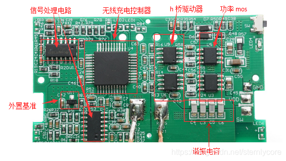
无线充电早期方案,MCU芯片,控制芯片,驱动芯片,运放全部独立,外围元件也相当多,复杂,不利于产品快速开发。
- SOC方案
SOC方案又分为两种类型:
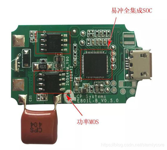
- MOS外置SOC方案
SOC芯片内部集成了无线驱动、H桥驱动、运放、MCU等功能。外置MOS可以自由配置,灵活性较高,是使用最广泛的一种SOC方案。
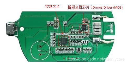
- DrMOS外置SOC方案
由一颗控制芯片和一颗智能全桥芯片 SmartBridge构成,智能全桥芯片集成了全桥 MOS和 Driver,可以实现 MOS 和Driver 匹配,大电流时需要考虑散热、效率。
无线充电方案相对成熟,推荐一些参考设计:
参考


 1万+
1万+

 被折叠的 条评论
为什么被折叠?
被折叠的 条评论
为什么被折叠?
 到【灌水乐园】发言


