


 本文是一篇学习记录贴,介绍了树莓派硬件控制相关内容。包括用C语言和shell脚本点亮LED、按键控制LED灯亮灭、PWM脉冲宽度调试、传感器感应灯等,还涉及步进电机、舵机、液晶屏的控制,以及动态库与静态库的制作方法。
本文为我的学习记录贴,我所记录的东西都是网上可以找到的文章或视频,侵权请联系删除
目录
本文为我的学习记录贴,我所记录的东西都是网上可以找到的文章或视频,侵权请联系删除
0、常用API
// 初始化:
wiringPISetup()         // 使用wiringPi的针脚编号方式
wiringPiSetupGpio()     // 使用Broadcom的针脚编号方式
// 设置模式:INPUT    PWM_OUTPUT  GPIO_CLOCK  SOFT_PWM_OUTPUT  SOFT_TONE_OUTPUT
// PWM_TONE_OUTPUT
pinMode(int PIN,OUTPUT)        // OUTPUT  INPUT   PWM_OUTPUT ...
// 设置电平:
degitalWrite(int Pin,0/1)      // 向指定GPIO写入高(1)/低(0)电平
// 读取电平:
digtalRead(int Pin)           //读取指定GPIO口逻辑电平
// 硬件PWM:
// 硬件PWM:树莓派仅4个GPIO口支持PWM  GPIO_1     GPIO_23     GPIO_24     GPIO_26
pinMode(int gpioPort, PWM_OUTPUT);      // 将指定GPIO设置为PWM模式
pwmSetMode(int mode);                 // PWM_MODE_BAL:调脉宽   PWM_MODE_MS:固定脉宽调占空比
pwmSetRange(unsigned int range);         // 设置脉宽   0 ~ 1024
pwmSetClock(int divisor);                // 设置分频
pwmWrite(int gpioPort, int pwmValue)  //向指定GPIO写入PWM值[0,1024]之间的值
//pwmToneWrite(int pin, int freq);
// 软件PWM:
// PWM范围[0, pwmRange]   初始PWM值为initialValue
softPwmCreate(int gpioPort, int initialValue, int pwmRange)   //在指定GPIO口上创建PWM引脚
softPwmWrite(int gpioPort, int pwmValue)          //更新PWM值到指定GPIO口
// 软件音频控制 压电元件
softToneCreate(int gpioPort);   //在指定GPIO口上创建软件控制的音频针脚
softToneWrite(int gpioPort, int frequency);     //更新指定频率到指定GPIO口


//注册回调函数callBackFunction,当以下降沿方式检测到指定的GPIO口上触
//发的中断信号时,回调函数将被执行
//中断方式:
wiringPiISR(int PIN, INT_EDGBE_FALLING,&callBackFunction)
一、点亮一个LED c语言
gpio readall //查看所有编码1、先使用cd命令进入一个目录中,这里我选择桌面目录
cd Desktop //切换到桌面目录2、使用nano编辑器或vi编辑器在该目录下建立一个c语言的文件led.c
3、使用编辑器写入代码led闪烁10次
#include<wiringPi.h>            //导入wiringPi.h头文件

#define Pin25 25                //作为LED的正极  37脚  负极选39脚或其他

int main()
{
    if(wiringPiSetup()<0)       //检查wiringPiSetup的输出,如果返回值小于0,说明树莓派没有安装该库,则程序中断并返回1
    return 1;
    pinMode(Pin25,OUTPUT);      //设置接口工作状态 输入状态:INPUT   输出状态:OUTPUT
    for(int i=0;i<10;i++)
    {
        digitalWrite(Pin25,1);  //使GPIO输出高电平
        delay(200);             //延时200ms
        digitalWrite(Pin25,0);
        delay(200);
    }
}
nano编辑器:ctrl+s保存 ctrl+x退出
4、输入命令运行代码
cc -Wall -o led led.c - lwiringPi                  // 使用cc命令进行编译
cc -Wall -o 生成的文件名 文件名.c - lwiringPi       // 使用cc命令进行编译   -Wall:编译时显示所以警告
                                                  //-o:指定编译后生成可执行程序的文件名  -lwiringPi:编译时动态加载wiringPi库
sudo ./led // 运行运行编译后的可执行程序
如果程序为死循环,则程序终止后LED状态不确定,相比于python是一个缺点
二、使用shell脚本点亮LED
1、必要的知识:
(1)shell脚本:
文中所有的shell脚本都是非必须文件,只使用.c文件就可以实现功能,如果是必要的文件(除.c以外的文件)会说明
编写好shell脚本后想要运行 这里假设shell脚本名称为test.sh
存放路径为 /home/pi/Desktop/test.sh
方法1:
1)不在Desktop目录下,执行
bash /home/pi/Desktop/test.sh2)在Desktop目录下,执行
bash test.sh方法2:
chmod +x test.sh //首先提升脚本权限,我是在脚本所在目录下执行的这一步,别的没试过1)不在Desktop目录下,执行
/home/pi/Desktop/test.sh2)在Desktop目录下,执行
./test.sh2、wiringPi常用的API
//初始化:
wiringPISetup()         //使用wiringPi的针脚编号方式
wiringPiSetupGpio()     //使用Broadcom的针脚编号方式
//设置模式:INPUT    PWM_OUTPUT  GPIO_CLOCK  SOFT_PWM_OUTPUT  SOFT_TONE_OUTPUT  //PWM_TONE_OUTPUT
pinMode(int PIN,OUTPUT)        //OUTPUT  INPUT   PWM_OUTPUT ...
//设置电平:
degitalWrite(int Pin,0/1)      //向指定GPIO写入高(1)/低(0)电平
//读取电平:
digtalRead(int Pin)           //读取指定GPIO口逻辑电平
//硬件PWM:
//硬件PWM:树莓派仅4个GPIO口支持PWM  GPIO_1     GPIO_23     GPIO_24     GPIO_26
pinMode(int gpioPort, PWM_OUTPUT);      //将指定GPIO设置为PWM模式
pwmWrite(int gpioPort, int pwmValue)     //向指定GPIO写入PWM值[0,1024]之间的值
//软件PWM:
//PWM范围[0, pwmRange]   初始PWM值为initialValue
softPwmCreate(int gpioPort, int initialValue, int pwmRange)   //在指定GPIO口上创建PWM引脚
softPwmWrite(int gpioPort, int pwmValue)          //更新PWM值到指定GPIO口
//软件音频控制 压电元件
softToneCreate(int gpioPort);   //在指定GPIO口上创建软件控制的音频针脚
softToneWrite(int gpioPort, int frequency);     //更新指定频率到指定GPIO口


//注册回调函数callBackFunction,当以下降沿方式检测到指定的GPIO口上触
//发的中断信号时,回调函数将被执行
//中断方式:
wiringPiISR(int PIN, INT_EDGBE_FALLING,&callBackFunction)
这里使用
初始化:        wiringPISetup()         使用wiringPi的针脚编号方式
设置模式:      pinMode(int PIN, OUTPUT)               OUTPUT  INPUT   PWM_OUTPUT ...
设置电平:       degitalWrite(int PIN, 0/1)          向指定GPIO写入高(1)/低(0)电平
3、test.sh
该脚本生成的可执行文件为led,可自行更改,led的gpio采用25脚
if语句用来判断如果可执行文件led存在,则打印 File already exists,然后执行文件,如果不存在则打印 The file does not exist, start building the executable file 并且生成可执行文件 led 然后执行
#! /bin/bash

# Set the GPIO
GPIO_PORT=25

#echo $GPIO_PORT
#echo shell test
#echo $0

#echo $(cd $(dirname $0); pwd)
#echo $(cd $(dirname $0); pwd)/led
#echo $(cd $(dirname $0); pwd)/led.c
#cd $(cd $(dirname $0); pwd)

BLINK_BIN=($(cd $(dirname $0); pwd)/led)
BLINK_SOURCE=($(cd $(dirname $0); pwd)/led.c)
echo $BLINK_BIN
echo $BLINK_SOURCE

if [ -f $BLINK_BIN ]; then
	echo File already exists
else
	echo The file does not exist, start building the executable file
	gcc $BLINK_SOURCE -o $BLINK_BIN -lwiringPi

fi

echo runing $BLINK_BIN
$BLINK_BIN $GPIO_PORT
最后一行的$BLINK_BIN其实就是/home/pi/Desktop/led 意思就是执行led文件
/home/pi/Desktop/led后面的$GPIO_PORT 就是传入文件的第一个参数,想加别的在后面加就可以了。如果不想使用shell脚本可以对.c文件进行简单修改即可。
4、led.c
//首先引入必须的头文件wiringPi.h,输入输出的头文件stdio.h   stdlib.h    unistd.h
#include<wiringPi.h>
#include<stdio.h>
#include<stdlib.h>
#include<unistd.h>

int main(int argc,char* argv[])
{
        //主函数里判断参数如果小于2个说明参数不够。下面获取程序执行需要的参数。
        //argv[0] 是命令本身,argv[1] 是命令后的第一个参数。也就是我在shell脚本中设置的GPIO口
        //这里我们将在命令后面指定GPIO口。通过参数将GPIO口的数值传给C程序。

        int Pin25=atoi(argv[1]);
        //准备wiring初始化,设置GPIO口的输出模式
        if(wiringPiSetup() < 0)
		return 1;
        pinMode(gpioPort,OUTPUT);

        int level=0;
        //进入无限循环,每次判断并切换level的数值,如同一个开关。
        //下面给GPIO口赋值,要么是0 要么是1,每次休眠秒。程序的最终效果也是让LED闪烁
        while(1)
        {
                level=(0==level)?1:0;
                digitalWrite(Pin25,level);
                delay(200);
        }
        return 0;
}
三、按键控制LED灯亮灭
1、用到的API
wiringPISetup()             // 初始化
pinMode(int PIN,OUTPUT)     // 设置模式  OUTPUT  INPUT   PWM_OUTPUT ...
degitalWrite(int PIN,0/1)   // 向指定GPIO写入高(1)/低(0)电平
digtalRead(int PIN)         // 读取指定GPIO口逻辑电平
//注册回调函数callBackFunction,当以下降沿方式检测到指定的GPIO口上触
//发的中断信号时,回调函数将被执行
wiringPiISR(int PIN, INT_EDGBE_FALLING,&callBackFunction) //中断
2、led_breathing_light.sh
这里shell脚本仅仅起到编译运行作用,不传参数
#! /bin/bash
# Filename: key_led.c
# This is a shell script
# Function: Key control LED
# Use interrupts

# Set the GPIO
#KEY_GPIO_PORT=0
#LED_GPIO_PORT=25

#echo $GPIO_PORT
# echo shell test
# echo $0
# echo $(cd $(dirname $0); pwd)
# echo $(cd $(dirname $0); pwd)/key_led
# echo $(cd $(dirname $0); pwd)/key_led.c
# cd $(cd $(dirname $0); pwd)

SCR_FILE=($(cd $(dirname $0); pwd)/key_led.c)
BIN_FILE=($(cd $(dirname $0); pwd)/key_led)
echo $SCR_FILE
echo $BIN_FILE

if [ -f $BIN_FILE ]; then
        echo File already exists
else
        echo The file does not exist, start building the executable file
        gcc $SCR_FILE -o $BIN_FILE -lwiringPi
fi

echo runing $BIN_FILE...
$BIN_FILE
#$KEY_GPIO_PORT $LED_GPIO_PORT
3、key_led.c
注意头文件
// Filename: key_led.c
// Function: Key control LED
// Use interrupts
// Timestamps are used for debounce
#include <wiringPi.h>
#include <stdio.h>
#include <stdlib.h>
#include <unistd.h>
#include <time.h>
#include <sys/time.h>

typedef enum
{
	false,
	true
} bool;
#define INVALID_GPIO_PORT -1
#define DEBOUNCE_TIME 500

int level = 0;
// int ledGpioPort = INVALID_GPIO_PORT;

long long recordMillisecond;

void interrup2DoSth(void);
long long getMillisecond();

 #define buttonGpioPort  	0
 #define ledGpioPort 	    25

 int main()
 {
//int main(int argc, char *argv[])
//{
//	if (argc < 3)
//	{
//		printf("Err");
//		return 1;
//	}

//	int buttonGpioPort = atoi(argv[1]);
//	int ledGpioPort = atoi(argv[2]);

	// int buttonGpioPort = 0;
	// int ledGpioPort = 25;

	if (wiringPiSetup() < 0)
		return 1;

	// register the function to deal with the button events
	wiringPiISR(buttonGpioPort, INT_EDGE_FALLING, &interrup2DoSth);

	pinMode(ledGpioPort, OUTPUT);

	int currentLevel = 0;
	while (true)
	{
		if (currentLevel != level)
		{
			printf("Caught an interrupt\n");
			currentLevel = level;
		}
	}
	return 0;
}

// The function to deal with the interrupt signal triggered by a button
void interrup2DoSth(void)
{
	//if (INVALID_GPIO_PORT == ledGpioPort)
	//{
	//	printf("LED GPIO port was not set properly\n");
	//	return;
	//}

	//in a time period, we only allow the signal to be triggered once
	long long currentMillisecond = getMillisecond();
	if(currentMillisecond - recordMillisecond < DEBOUNCE_TIME)
	{
		printf("The trigger time is too short\n");
		return;
	}

	if (0 == level)
	{
		level = 1;
	}
	else
	{
		level = 0;
	}
	// turn on or tuen off the LED
	digitalWrite(ledGpioPort, level);

	//update the record time, to prepared for the next round debouncing
	recordMillisecond = currentMillisecond;
}

//Get the milliseconds elapsed since Jan. 1, 1970
long long getMillisecond()
{
	struct timeval tv;
	gettimeofday(&tv,NULL);

	return (long long)tv.tv_sec*1000 + (long long)tv.tv_usec/1000;

}
四、PWM脉冲宽度调试
这里PWM的API没有用完,下面三个实验没有要求频率,所以就没有使用固定脉宽调节占空比的方法,仅仅用来熟悉PWM,如果要控制舵机等对频率有要求的组件,请参考第七小结
1、硬件PWM 呼吸灯
(1)用到的API
//硬件PWM:树莓派仅4个GPIO口支持PWM  GPIO_1     GPIO_23     GPIO_24     GPIO_26

pinMode(int gpioPort, PWM_OUTPUT);      //将指定GPIO设置为PWM模式
pwmWrite(int gpioPort, int pwmValue);   //向指定GPIO写入PWM值
(2)led_breathing_light.sh
#! /bin/bash
# filename:led_breathing_light.sh
# This is a shell script
# Function: LED breathing light

# Set the GPIO
#KEY_GPIO_PORT=0
#LED_GPIO_PORT=25

#echo $GPIO_PORT
# echo shell test
# echo $0
# echo $(cd $(dirname $0); pwd)
# echo $(cd $(dirname $0); pwd)/led_breathing_light
# echo $(cd $(dirname $0); pwd)/led_breathing_light.c
# cd $(cd $(dirname $0); pwd)

SCR_FILE=($(cd $(dirname $0); pwd)/led_breathing_light.c)
BIN_FILE=($(cd $(dirname $0); pwd)/led_breathing_light)
echo $SCR_FILE
echo $BIN_FILE

if [ -f $BIN_FILE ]; then
        echo File already exists
else
        echo The file does not exist, start building the executable file
        gcc $SCR_FILE -o $BIN_FILE -lwiringPi
        #gcc -o $BIN_FILE $SCR_FILE -lwiringPi -lpthread
fi

echo runing $BIN_FILE...
sudo ./led_breathing_light
#$BIN_FILE
#$KEY_GPIO_PORT $LED_GPIO_PORT
(3)led_breathing_light.c
// Filename:led_breathing_light.c
// Function: LED breathing light

// pinMode(int gpioPort, PWM_OUTPUT);      //将指定GPIO设置为PWM模式
// pwmWrite(int gpioPort, int pwmValue);   //向指定GPIO写入PWM值
//硬件PWM:树莓派仅4个GPIO口支持PWM  GPIO_1     GPIO_23     GPIO_24     GPIO_26
#include <wiringPi.h>
#include <stdio.h>
#include <stdlib.h>
#include <stdint.h>

#define PWM_GPIO_PORT   23

const int MAX_PWM_VALUE = 1023;

int main()
{
    printf("hello world\n");

	if (wiringPiSetup() < 0)
		return 1;

    pinMode(PWM_GPIO_PORT, PWM_OUTPUT);         //Set mode to PWM_OUTPUT
                                                //INPUT   OUTPUT    PWM_OUTPUT  GPIO_CLOCK  SOFT_PWM_OUTPUT
                                                //SOFT_TONE_OUTPUT  PWM_TONE_OUTPUT
    printf("mode OK\n");

    int bringhtness = 0;        //PWM value

    while (1)
    {
        for(bringhtness = 0; bringhtness <= MAX_PWM_VALUE; ++bringhtness)
        {
            pwmWrite(PWM_GPIO_PORT, bringhtness);   //Set the PWM value for the specified PWM pin
            delay(1);           //
        }

         for(bringhtness = MAX_PWM_VALUE; bringhtness >= 0; --bringhtness)
        {
            pwmWrite(PWM_GPIO_PORT, bringhtness);   //Set the PWM value for the specified PWM pin
            delay(1);
        }
    }
    return 0;
}
2、软件PWM 呼吸灯
相较于硬件PWM,软件PWM会占用稍多点的CPU资源。每个软件PWM接口的CPU占用率为”千分之5“左右
(1)用到的API
//软件PWM
//在指定GPIO口上创建PWM引脚
//PWM范围[0, pwmRange]   初始PWM值为initialValue
softPwmCreate(int gpioPort, int initialValue, int pwmRange);
//如果未使用softPwmCreate();则下面API会被悄悄忽略掉
softPwmWrite(int gpioPort, int pwmValue);     //更新PWM值到指定GPIO口
(2)pwm_software.sh
#! /bin/bash
# filename:pwm_software.sh
# This is a shell script
# Function: LED breathing light

# Set the GPIO
#KEY_GPIO_PORT=0
#LED_GPIO_PORT=25

#echo $GPIO_PORT
# echo shell test
# echo $0
# echo $(cd $(dirname $0); pwd)
# echo $(cd $(dirname $0); pwd)/pwm_software
# echo $(cd $(dirname $0); pwd)/pwm_software.c
# cd $(cd $(dirname $0); pwd)

SCR_FILE=($(cd $(dirname $0); pwd)/pwm_software.c)
BIN_FILE=($(cd $(dirname $0); pwd)/pwm_software)
echo $SCR_FILE
echo $BIN_FILE

if [ -f $BIN_FILE ]; then
        echo File already exists
else
        echo The file does not exist, start building the executable file
        gcc $SCR_FILE -o $BIN_FILE -lwiringPi
        #gcc -o $BIN_FILE $SCR_FILE -lwiringPi -lpthread
fi

echo runing $BIN_FILE...
sudo ./pwm_software
#$BIN_FILE
#$KEY_GPIO_PORT $LED_GPIO_PORT
(3)pwm_software.c
注意头文件
// Filename: pwm_software.c
// Function: LED breathing light

//硬件PWM
// pinMode(int gpioPort, PWM_OUTPUT);      //将指定GPIO设置为PWM模式
// pwmWrite(int gpioPort, int pwmValue);   //向指定GPIO写入PWM值
//硬件PWM:树莓派仅4个GPIO口支持PWM  GPIO_1     GPIO_23     GPIO_24     GPIO_26

//软件PWM
//在指定GPIO口上创建PWM引脚
//PWM范围[0, pwmRange]   初始PWM值为initialValue
// softPwmCreate(int gpioPort, int initialValue, int pwmRange);
//如果未使用softPwmCreate();则下面API会被悄悄忽略掉
//softPwmWrite(int gpioPort, int pwmValue);     //更新PWM值到指定GPIO口
#include <wiringPi.h>
#include <softPwm.h>
#include <stdio.h>
#include <stdlib.h>
#include <stdint.h>

#define PWM_GPIO_PORT   0


int main()
{
    printf("hello world\n");

	if (wiringPiSetup() < 0)
		return 1;

    // pinMode(PWM_GPIO_PORT, PWM_OUTPUT);         //Set mode to PWM_OUTPUT
    //                                             //INPUT   OUTPUT    PWM_OUTPUT  GPIO_CLOCK  SOFT_PWM_OUTPUT
    //                                             //SOFT_TONE_OUTPUT  PWM_TONE_OUTPUT
    softPwmCreate(PWM_GPIO_PORT, 0, 100);
    printf("mode OK\n");

    int value = 0;        //PWM value

    while (1)
    {
        for(value = 1; value <= 100; ++value)
        {
            softPwmWrite(PWM_GPIO_PORT, value);   //Set the PWM value for the specified PWM pin
            delay(10);           //
        }

        for(value = 100; value >= 1; --value)
        {
            softPwmWrite(PWM_GPIO_PORT, value);   //Set the PWM value for the specified PWM pin
            delay(10);           //
        }
    }
    return 0;
}
3、pwm控制压电元件 无源蜂鸣器
(1)用到的API
softToneCreate(int gpioPort);   //在指定GPIO口上创建软件控制的音频针脚
softToneWrite(int gpioPort, int frequency);     //更新指定频率到指定GPIO口
(2)soft_tone.sh
#! /bin/bash
# filename: soft_tone.sh
# This is a shell script
# Function: Drive the passive buzzer

# Set the GPIO
#KEY_GPIO_PORT=0
#LED_GPIO_PORT=25

#echo $GPIO_PORT
# echo shell test
# echo $0
# echo $(cd $(dirname $0); pwd)
# echo $(cd $(dirname $0); pwd)/soft_tone
# echo $(cd $(dirname $0); pwd)/soft_tone.c
# cd $(cd $(dirname $0); pwd)

SCR_FILE=($(cd $(dirname $0); pwd)/soft_tone.c)
BIN_FILE=($(cd $(dirname $0); pwd)/soft_tone)
echo $SCR_FILE
echo $BIN_FILE

if [ -f $BIN_FILE ]; then
        echo File already exists
else
        echo The file does not exist, start building the executable file
        gcc $SCR_FILE -o $BIN_FILE -lwiringPi
        #gcc -o $BIN_FILE $SCR_FILE -lwiringPi -lpthread
fi

echo runing $BIN_FILE...
# sudo ./soft_tone
$BIN_FILE
#$KEY_GPIO_PORT $LED_GPIO_PORT
(3)soft_tone.c
注意头文件
// Filename: soft_tone.c
// Function: Drive the passive buzzer

//使用的API
// softToneCreate(int gpioPort);   //在指定GPIO口上创建软件控制的音频针脚
// softToneWrite(int gpioPort, int frequency);     //更新指定频率到指定GPIO口

#include <wiringPi.h>
#include <softTone.h>
#include <stdio.h>
#include <stdlib.h>
#include <stdint.h>

typedef enum {false, true}bool;

int scale[23] = {659,659,0,659,0,523,659,0,784,0,0,0,392,0,0,0,523,392,0,0,330};

#define TONE_GPIO_PORT   0


int main()
{
    printf("hello world\n");

    wiringPiSetup();
    if(0 != softToneCreate(TONE_GPIO_PORT))
    {
        printf("Creat software tone failed\n");
        return 1;
    }

    int i;
    int loopCount = 0;
    int arrayLength = sizeof(scale)/sizeof(int);
    while(true)
    {
        printf("Has played the music for %d timers\n", loopCount);
        for(i = 0;i < arrayLength;++i)
        {
            softToneWrite(TONE_GPIO_PORT, scale[i]);
            delay(200);

        }
        delay(500);
        ++loopCount;

    }

    return 0;
}
五、传感器感应灯
和按键控制LED灯一样,按键端口换成了传感器DO口
1、用到的API
//使用的API
pinMode(int gpioPort, INPUT);       //热释电传感器GPIO设置为输入状态
pinMode(int gpioPort, OUTPUT);      //LED GPIO设置为输出状态
digitalRead(int gpioPort);          //读取热释电传感器状态
digitalWrite(int gpioPort, level);  //输出高/低电平到LED
2、sense_light.sh
#! /bin/bash
# filename: sense_light.sh
# This is a shell script
# Function: Human proximity sensor light

#chmod +x sense_light.sh

# Set the GPIO
#KEY_GPIO_PORT=0
#LED_GPIO_PORT=25

#echo $GPIO_PORT
# echo shell test
# echo $0
# echo $(cd $(dirname $0); pwd)
# echo $(cd $(dirname $0); pwd)/sense_light
# echo $(cd $(dirname $0); pwd)/sense_light.c
# cd $(cd $(dirname $0); pwd)

SCR_FILE=($(cd $(dirname $0); pwd)/sense_light.c)
BIN_FILE=($(cd $(dirname $0); pwd)/sense_light)
echo $SCR_FILE
echo $BIN_FILE

if [ -f $BIN_FILE ]; then
        echo File already exists
else
        echo The file does not exist, start building the executable file
        gcc $SCR_FILE -o $BIN_FILE -lwiringPi
        #gcc -o $BIN_FILE $SCR_FILE -lwiringPi -lpthread
fi

echo runing $BIN_FILE...
# sudo ./sense_light
$BIN_FILE
#$KEY_GPIO_PORT $LED_GPIO_PORT
3、sense_light.c
// Filename: sense_light.c
// Function: Human proximity sensor light

//使用的API
// pinMode(int gpioPort, INPUT);       //热释电传感器GPIO设置为输入状态
// pinMode(int gpioPort, OUTPUT);      //LED GPIO设置为输出状态
// digitalRead(int gpioPort);          //读取热释电传感器状态
// digitalWrite(int gpioPort, level);  //输出高/低电平到LED

#include <wiringPi.h>
#include <stdio.h>
#include <stdlib.h>
#include <stdint.h>

//传感器输入信号检测口                一般传感器的DO口
#define PYROELECTRIC_MODULE_GPIO_PORT   7       //7

#define LED_GPIO_PORT_1                 0       //11
#define LED_GPIO_PORT_2                 1       //12


int main()
{
    printf("hello world\n");

    wiringPiSetup();

    pinMode(PYROELECTRIC_MODULE_GPIO_PORT, INPUT);
    pinMode(LED_GPIO_PORT_1, OUTPUT);
    pinMode(LED_GPIO_PORT_2, OUTPUT);

    // digitalWrite(LED_GPIO_PORT_1, 1);
    // digitalWrite(LED_GPIO_PORT_2, 1);

    while(1)
    {
        int currentLevel = digitalRead(PYROELECTRIC_MODULE_GPIO_PORT);
         printf("Current_level: %d\n",currentLevel);
        delay(30);
        if(currentLevel == 1)
        {
            digitalWrite(LED_GPIO_PORT_1, 0);
            digitalWrite(LED_GPIO_PORT_2, 1);
        }
        else
        {
            digitalWrite(LED_GPIO_PORT_1, 1);
            digitalWrite(LED_GPIO_PORT_2, 0);
        }
        delay(100);
    }

    // return 0;
}
六、步进电机控制 四相四拍
引脚对应:
//文中采用wiringPi编码的0,1,2,3
#define GPIO_PORT_0                 0       //11
#define GPIO_PORT_1                 1       //12
#define GPIO_PORT_2                 2       //13
#define GPIO_PORT_3                 3       //15

IN1    GPIO_PORT_0
IN2    GPIO_PORT_1
IN3    GPIO_PORT_2
IN4    GPIO_PORT_3
VCC    5V
GND    0V
1、控制电机正反转
(1)motor.sh
#! /bin/bash
# filename: motor.sh
# This is a shell script
# Function: Stepper motor control

#chmod +x motor.sh

# Set the GPIO
#KEY_GPIO_PORT=0
#LED_GPIO_PORT=25

#echo $GPIO_PORT
# echo shell test
# echo $0
# echo $(cd $(dirname $0); pwd)
# echo $(cd $(dirname $0); pwd)/motor
# echo $(cd $(dirname $0); pwd)/motor.c
# cd $(cd $(dirname $0); pwd)

SCR_FILE=($(cd $(dirname $0); pwd)/motor.c)
BIN_FILE=($(cd $(dirname $0); pwd)/motor)
echo $SCR_FILE
echo $BIN_FILE

if [ -f $BIN_FILE ]; then
        echo File already exists
else
        echo The file does not exist, start building the executable file
        gcc $SCR_FILE -o $BIN_FILE -lwiringPi
        #gcc -o $BIN_FILE $SCR_FILE -lwiringPi -lpthread
fi

echo runing $BIN_FILE...
# sudo ./motor
$BIN_FILE
#$KEY_GPIO_PORT $LED_GPIO_PORT
(2)motor.c
// Filename: motor.c
// Function: Stepper motor control
// Component:Geared stepper motor(28YBJ-48)     Driver board(ULN2003)

//API used
// pinMode(int gpioPort, OUTPUT);      //Set the specified IO port mode
// digitalWrite(int gpioPort, level);  //Set the specified IO port level

#include <wiringPi.h>
#include <stdio.h>
#include <stdlib.h>
#include <stdint.h>

#define CLOCKWISE                   1       //Clockwise
#define COUNTER_CLOCKWISE           2       //Counterclockwise

void rotate(int* pins, int direction, int delayMS);

#define GPIO_PORT_0                 0       //11
#define GPIO_PORT_1                 1       //12
#define GPIO_PORT_2                 2       //13
#define GPIO_PORT_3                 3       //15

// Define Clockwise or Counterclockwise
int direction = CLOCKWISE;
int pins[4] = {GPIO_PORT_0, GPIO_PORT_1, GPIO_PORT_2, GPIO_PORT_3};

int main()
{
    printf("hello world\n");

    wiringPiSetup();

    pinMode(GPIO_PORT_0, OUTPUT);
    pinMode(GPIO_PORT_1, OUTPUT);
    pinMode(GPIO_PORT_2, OUTPUT);
    pinMode(GPIO_PORT_3, OUTPUT);

    while(1)
    {
        rotate(pins, direction, 1);
    }


    return 0;
}

/**
 * Rotate the stepper motor.
 * @param pins      A pointer which points to the pins number array.
 * @param direction CLOCKISE for clockwise rotation, COUNTER CLOCKIISE for counter clockwise rotation.
 * @param delayMS   Change the motor speed,Decreasing delayMS accelerates the motor
*/
void rotate(int* pins, int direction, int delayMS)
{
    int i = 0;
    int j = 0;
    for(i = 0; i < 4; i++)
    {
        for(j = 0; j < 4; j++)
        {
            int pinIndex = (CLOCKWISE == direction) ? (3 - j) : j;
            if(j ==i )
            {
                digitalWrite(pins[pinIndex], 1);
            }
            else
            {
                digitalWrite(pins[pinIndex], 0);
            }
            delay(delayMS);
        }

    }
}
2、控制电机转速
加了一个电机停止函数
(1)speed.sh
#! /bin/bash
# filename: speedup.sh
# This is a shell script
# Function: Stepper motor control, direction + speed

#chmod +x speedup.sh

# Set the GPIO
#KEY_GPIO_PORT=0
#LED_GPIO_PORT=25

#echo $GPIO_PORT
# echo shell test
# echo $0
# echo $(cd $(dirname $0); pwd)
# echo $(cd $(dirname $0); pwd)/speedup
# echo $(cd $(dirname $0); pwd)/speedup.c
# cd $(cd $(dirname $0); pwd)

SCR_FILE=($(cd $(dirname $0); pwd)/speedup.c)
BIN_FILE=($(cd $(dirname $0); pwd)/speedup)
echo $SCR_FILE
echo $BIN_FILE

if [ -f $BIN_FILE ]; then
        echo File already exists
else
        echo The file does not exist, start building the executable file
        gcc $SCR_FILE -o $BIN_FILE -lwiringPi
        #gcc -o $BIN_FILE $SCR_FILE -lwiringPi -lpthread
fi

echo runing $BIN_FILE...
# sudo ./speedup
$BIN_FILE
#$KEY_GPIO_PORT $LED_GPIO_PORT
(2)speedup.c
// Filename: speedup.c
// Function: Stepper motor control, direction + speed
// Component:Geared stepper motor(28YBJ-48)     Driver board(ULN2003)

//API used
// pinMode(int gpioPort, OUTPUT);      //Set the specified IO port mode
// digitalWrite(int gpioPort, level);  //Set the specified IO port level

#include <wiringPi.h>
#include <stdio.h>
#include <stdlib.h>
#include <stdint.h>

#define CLOCKWISE                   1       //Clockwise
#define COUNTER_CLOCKWISE           2       //Counterclockwise
#define MAX_DELAY                   15
#define MIN_DELAY                   1

void rotate(int* pins, int direction, int delayMS);
void stop(int* pins);

#define GPIO_PORT_0                 0       //
#define GPIO_PORT_1                 1       //
#define GPIO_PORT_2                 2       //
#define GPIO_PORT_3                 3       //

// Define Clockwise or Counterclockwise
int direction = CLOCKWISE;
int pins[4] = {GPIO_PORT_0, GPIO_PORT_1, GPIO_PORT_2, GPIO_PORT_3};

int main()
{
    printf("hello world\n");

    wiringPiSetup();

    pinMode(GPIO_PORT_0, OUTPUT);
    pinMode(GPIO_PORT_1, OUTPUT);
    pinMode(GPIO_PORT_2, OUTPUT);
    pinMode(GPIO_PORT_3, OUTPUT);

    int delayMS = MAX_DELAY;

    while(1)
    {
        int i;
        for(i = 0; i < 10; i++)
        {
            rotate(pins, direction, delayMS);
        }
        --delayMS;
        if(delayMS < MIN_DELAY)
        {
            delayMS = MAX_DELAY;
            stop(pins);
            delay(1000);
        }

        rotate(pins, direction, 4);
    }


    return 0;
}

/**
 * Rotate the stepper motor.
 * @param pins      A pointer which points to the pins number array.
 * @param direction CLOCKISE for clockwise rotation, COUNTER CLOCKIISE for counter clockwise rotation.
 * @param delayMS   Change the motor speed,Decreasing delayMS accelerates the motor
*/
void rotate(int* pins, int direction, int delayMS)
{
    int i = 0;
    int j = 0;
    for(i = 0; i < 4; i++)
    {
        for(j = 0; j < 4; j++)
        {
            int pinIndex = (CLOCKWISE == direction) ? (3 - j) : j;
            if(j ==i )
            {
                digitalWrite(pins[pinIndex], 1);
            }
            else
            {
                digitalWrite(pins[pinIndex], 0);
            }
            delay(delayMS);
        }

    }
}

/**
 * Stop the stepper motor by setting all of its inputs to low level.
 * @param pins      A pointer which points to the pins number array.
*/
void stop(int* pins)
{
    int i;
    for(i = 0; i < 4; i++)
    {
        digitalWrite(pins[i], 0);
    }
}
七、舵机控制 (SG90)
引脚对应:
Red line: 5V
Blue or yellow line: Signal line
Black or brown lines: GND
1、用到的API
// API used
pinMode(int gpioPort, PWM_OUTPUT);      // Set the specified IO port to hardware PWM mode
pwmWrite(int gpioPort, int pwmValue);   // Writes the PWM value to the specified IO port
// pwmToneWrite(int pin, int freq);
pwmSetMode(int mode);                //PWM_MODE_BAL:调脉宽   PWM_MODE_MS:脉宽固定调占空比
pwmSetRange(unsigned int range);     // Set the PWM pulse width   0 ~ 1024
pwmSetClock(int divisor);            // Set the PWM divider factor
网上很多人说树莓派PWM频率为19.2MHZ,但是我使用时发现和我的对不上,我这里测得为54MHZ,身边有示波器的测一下就好了,没有的那就两个都试试,也就改两个数据。
并且我这里舵机没有校准,想要更精准的就要自己再查资料了
2、servo.sh
#! /bin/bash
# filename: servo.sh
# This is a shell script
# Function: Servo control

#chmod +x servo.sh

# Set the GPIO
#KEY_GPIO_PORT=0
#LED_GPIO_PORT=25

#echo $GPIO_PORT
# echo shell test
# echo $0
# echo $(cd $(dirname $0); pwd)
# echo $(cd $(dirname $0); pwd)/servo
# echo $(cd $(dirname $0); pwd)/servo.c
# cd $(cd $(dirname $0); pwd)

SCR_FILE=($(cd $(dirname $0); pwd)/servo.c)
BIN_FILE=($(cd $(dirname $0); pwd)/servo)
echo $SCR_FILE
echo $BIN_FILE

if [ -f $BIN_FILE ]; then
        echo File already exists
else
        echo The file does not exist, start building the executable file
        gcc $SCR_FILE -o $BIN_FILE -lwiringPi
        #gcc -o $BIN_FILE $SCR_FILE -lwiringPi -lpthread
fi

echo runing $BIN_FILE...
sudo ./servo
# $BIN_FILE
#$KEY_GPIO_PORT $LED_GPIO_PORT
3、servo.c
// Filename: servo.c
// Function: Servo control
// Component: Servo(SG90)   0.5ms:0     1ms:45      1.5ms:90    2ms:135     2.5ms:180
// Connection: Red line: 5V~6V          Blue or yellow line: Signal line        Black or brown lines: GND

// API used
// pinMode(int gpioPort, PWM_OUTPUT);      // Set the specified IO port to hardware PWM mode
// pwmWrite(int gpioPort, int pwmValue);   // Writes the PWM value to the specified IO port
// pwmToneWrite(int pin, int freq);
// pwmSetMode(int mode);                    //PWM_MODE_BAL:调脉宽   PWM_MODE_MS:调占空比
// pwmSetRange(unsigned int range);         // Set the PWM pulse width   0 ~ 1024
// pwmSetClock(int divisor);                // Set the PWM divider factor

// freq(HZ)=19.2MHZ / divisor / range
// 19200 000 / 1000 = 19200
// 19200 / 384 = 50HZ

// freq(HZ)=54MHZ / divisor / range
// 54000 000 / 1000 = 54000
// 54000 / 1080 = 50HZ

// HardwarePWM:Raspberry Pi only has 4 IO ports to support hardware PWM:  GPIO_1     GPIO_23     GPIO_24     GPIO_26


#include <wiringPi.h>
#include <stdio.h>
#include <stdlib.h>
#include <stdint.h>

#define PWM_GPIO_PORT   1


void pwm_servo_set_angle(int pin, float angle);


int main()
{
    printf("hello world\n");

    wiringPiSetup();
    pinMode(PWM_GPIO_PORT, PWM_OUTPUT);         //Set mode to PWM_OUTPUT
    pwmSetMode(PWM_MODE_MS);
    pwmSetRange(1000);
    pwmSetClock(1080);

    while(1)
    {
        // pwmWrite(PWM_GPIO_PORT, 25);
        pwm_servo_set_angle(PWM_GPIO_PORT,0);
        printf("0");
        delay(2000);
        // pwmWrite(PWM_GPIO_PORT, 75);
        pwm_servo_set_angle(PWM_GPIO_PORT,90);
        printf("90");
        delay(2000);
        // pwmWrite(PWM_GPIO_PORT, 125);
        pwm_servo_set_angle(PWM_GPIO_PORT,180);
        printf("180");
        delay(2000);
        // pwmWrite(PWM_GPIO_PORT, 75);
        pwm_servo_set_angle(PWM_GPIO_PORT,90);
        printf("90");
        delay(2000);


    }

    return 0;
}

/**
 * Rotate the stepper motor.
 * @param pin       GPIO
 * @param angle CLOCKISE for clockwise rotation, COUNTER CLOCKIISE for counter clockwise rotation.
*/

void pwm_servo_set_angle(int pin, float angle)
{
    pwmWrite(pin, ((angle / 180.0) * 100 + 25));
}
八、驱动液晶屏 lcd1602
1、树莓派直接连接lcd1602
(1)线路连接
引脚名称 wiringPi  引脚号
VSS       GND
VDD       5V
V0        连接到电位器的中间脚,电位器的另外两脚连接GND与5V,电位器是必要的
           接电源对比度最低,接地对比度最高,没有电位器就直接接地,虽然效果不好
           但也可以看清
RS        11       //26    寄存器选择
RW        GND
E         10       //24    使能端
DO        0        //11    4位数据模式下D0~D3不接
D1        1        //12
D2        2        //13
D3        3        //15
D4        4        //16
D5        5        //18
D6        6        //22
D7        7        //7
A         5V       //液晶背光正极
K         GND      //液晶背光负极
(2)用到的API
// API used
pinMode(int gpioPort, PWM_OUTPUT);      // Set the specified IO port to hardware PWM mode
lcdInit (const int rows, const int cols, const int bits,
    const int rs, const int strb,
 	const int d0, const int d1, const int d2, const int d3, const int d4,
 	const int d5, const int d6, const int d7) ;     //初始化LCD,在调用其他LCD函数前一定要调用
lcdClear(const int fd) ;             //清屏
lcdCursor      (const int fd, int state) ;    //打开/关闭光标显示
lcdCursorBlink (const int fd, int state) ;    //打开/关闭光标闪烁
lcdPosition    (const int fd, int x, int y) ; //设置光标位置
lcdPuts        (const int fd, const char *string) ;       //在LCD上显示一个字符串

//  lcdHome        (const int fd) ;
//  lcdDisplay     (const int fd, int state) ;
//  lcdSendCommand (const int fd, unsigned char command) ;
//  lcdCharDef     (const int fd, int index, unsigned char data [8]) ;
//  lcdPutchar     (const int fd, unsigned char data) ;
//  lcdPrintf      (const int fd, const char *message, ...) ;
(3)lcd.sh
注意编译时后面跟了个 -lwiringPiDev
#! /bin/bash
# filename: lcd.sh
# This is a shell script
# Function: Drive LCD1602

#chmod +x lcd.sh

# Set the GPIO
#KEY_GPIO_PORT=0
#LED_GPIO_PORT=25


SCR_FILE=($(cd $(dirname $0); pwd)/lcd.c)
BIN_FILE=($(cd $(dirname $0); pwd)/lcd)
echo $SCR_FILE
echo $BIN_FILE

if [ -f $BIN_FILE ]; then
        echo File already exists
else
        echo The file does not exist, start building the executable file
        gcc $SCR_FILE -o $BIN_FILE -lwiringPi -lwiringPiDev
        #gcc -o $BIN_FILE $SCR_FILE -lwiringPi -lpthread
fi

echo runing $BIN_FILE...
# sudo ./lcd
$BIN_FILE
#$KEY_GPIO_PORT $LED_GPIO_PORT
(4)lcd.c
注意头文件
// Filename: lcd_i2c.c
// Function: Drive LCD1602
// Component: lcd1602()     Hitachi HD44780控制器       电位器10k*1
// Connection:

// API used
// pinMode(int gpioPort, PWM_OUTPUT);      // Set the specified IO port to hardware PWM mode
// lcdInit (const int rows, const int cols, const int bits,
//     const int rs, const int strb,
// 	const int d0, const int d1, const int d2, const int d3, const int d4,
// 	const int d5, const int d6, const int d7) ;         //初始化LCD,在调用其他LCD函数前一定要调用
// lcdClear(const int fd) ;             //清屏
//lcdCursor      (const int fd, int state) ;    //打开/关闭光标显示
//lcdCursorBlink (const int fd, int state) ;    //打开/关闭光标闪烁
//lcdPosition    (const int fd, int x, int y) ; //设置光标位置
//lcdPuts        (const int fd, const char *string) ;       //在LCD上显示一个字符串


//  lcdHome        (const int fd) ;
//  lcdDisplay     (const int fd, int state) ;
//  lcdSendCommand (const int fd, unsigned char command) ;
//  lcdCharDef     (const int fd, int index, unsigned char data [8]) ;
//  lcdPutchar     (const int fd, unsigned char data) ;
//  lcdPrintf      (const int fd, const char *message, ...) ;


#include <wiringPi.h>
#include <stdio.h>
#include <stdlib.h>
#include <stdint.h>

#include<unistd.h>
#include<string.h>
#include<time.h>
#include<lcd.h>

typedef enum {false, true}bool;

//lcd行与列
const int ROWS = 2;
const int COLUMNS = 16;

//RS与E的引脚
#define GPIO_PIN_NUMBER_RS   11
#define GPIO_PIN_NUMBER_E    10
//显示模式  4位显示模式/8位显示模式
#define DATABITS_4           4
#define DATABITS_8           8

static int lcdHandle;

void scrollMessage(int row, int width, const char* message);
void waitForEnter();

int main()
{
    printf("hello world\n");

    struct tm *t;
    time_t tim;
    char buf[32];

    int dataBits = DATABITS_8;        //8位显示模式
    const char* displayMassage = "Raspberry Pi is amazing";         //要显示的字符串

    wiringPiSetup();

    //LCD初始化
    if(4 == dataBits)
    {
        //行数 列数 位数 RS脚 E脚   lcd数据口
        lcdHandle = lcdInit(ROWS, COLUMNS, dataBits, GPIO_PIN_NUMBER_RS, GPIO_PIN_NUMBER_E, 4, 5, 6, 7, 0, 0, 0, 0);
    }
    else if (8 == dataBits)
    {
         lcdHandle = lcdInit(ROWS, COLUMNS, dataBits, GPIO_PIN_NUMBER_RS, GPIO_PIN_NUMBER_E, 0, 1, 2, 3, 4, 5, 6, 7);
    }
    else
    {
        fprintf(stderr, "data bits must be to 4 or 8\n");
        return -1;
    }

    if(lcdHandle < 0)
    {
        fprintf(stderr, "lcdInit failed\n");
        return -1;
    }

    lcdClear(lcdHandle);                            //清屏
    lcdPosition(lcdHandle, (4 - 1), (1 - 1));       //将光标置于第4列,第1行
    lcdPuts(lcdHandle, "RPi");                      //显示字符串    字符串起始位置就是光标所在位置
    lcdPosition(lcdHandle,(5 - 1), (2 - 1));        //将光标置于第5列,第2行
    lcdPuts(lcdHandle, "codelast");                 //显示字符串

    waitForEnter();

    lcdClear(lcdHandle);                            //清屏
    lcdPosition(lcdHandle, (1 - 1), (1 - 1));       //将光标置于第1列,第1行
    lcdCursor(lcdHandle, true);                     //打开光标显示
    lcdCursorBlink(lcdHandle, true);                //打开光标闪烁

    waitForEnter();

    lcdCursor(lcdHandle, false);                     //关闭光标显示
    lcdCursorBlink(lcdHandle, false);                //关闭光标闪烁
    lcdClear(lcdHandle);                             //清屏
    lcdPuts(lcdHandle, "Will scroll...");            //显示字符串

    waitForEnter();

    while(1)
    {
        scrollMessage(0, COLUMNS, displayMassage);      //滚动第一行显示的内容

        //在lcd上显示当前时间
        time(&tim);
        t = localtime(&tim);
        sprintf(buf, "%02d:%02d:%02d",t->tm_hour,t->tm_min,t->tm_sec);

        lcdPosition(lcdHandle, (COLUMNS - 8)/2, 1);
        lcdPuts(lcdHandle, buf);

    }

    return 0;
}

/**
 * 等待Enter,不按Enter程序就停在这里,按Enter进入下一步
*/
void waitForEnter()
{
    printf("Press ENTER to continue: ");
    (void)fgetc(stdin);
}

/**
 * 屏幕滚动显示
 * @param row   行
 * @param width 宽度
 * @param message   要显示的内容
*/
void scrollMessage(int row, int width, const char* message)
{
    char buf[32] = {0};
    memset(buf, 0, sizeof(buf));

    static int position = 0;
    static int timer = 0;

    if(millis() < timer)
    {
        return;
    }

    timer = millis() + 200;
    strncpy(buf, &message[position], width);
    buf[width] = 0;

    lcdPosition(lcdHandle,0, row);
    lcdPuts(lcdHandle, buf);

    if(++position == (strlen(message) - width))
    {
        position = 0;
    }
}
2、使用lcd1602 i2c转换模块(PCF8574)
(1)配置
安装与使用测试i2c总线工具 i2c tools
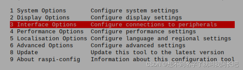
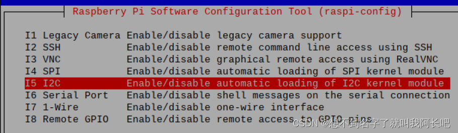
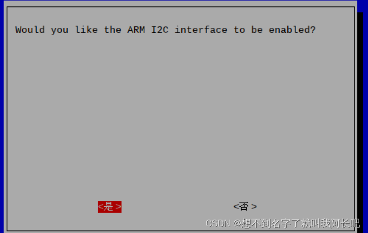
开启12C: sudo raspi-config进入第三项
重启树莓派
运行sudo nano /etc/modules
sudo nano /etc/modules增加以下两行并保存退出
i2c-bcm2708
i2c-dev
(2)安装i2c tools 安装1次就好
以后再用只要配置好i2c,然后查询地址就可以了,当然这一步也可以做,可以用来检查软件更新
输入命令安装:
sudo apt-get install i2c-tools输入命令测试是否安装正确:
sudo i2cdetect -l 看到下面第二条信息说明安装正确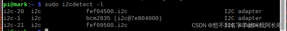
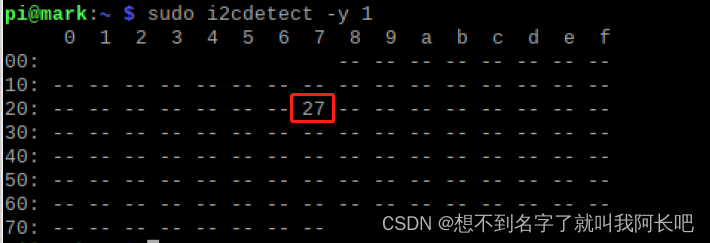
(3)i2c设备查询
命令:
sudo i2cdetect -y 1我这里显示地址就是0x27
(4)lcd_i2c.sh
#! /bin/bash
# filename: lcd_i2c.sh
# This is a shell script
# Function: Drive LCD1602

#chmod +x lcd_i2c.sh

# Set the GPIO
#KEY_GPIO_PORT=0
#LED_GPIO_PORT=25


SCR_FILE=($(cd $(dirname $0); pwd)/lcd_i2c.c)
BIN_FILE=($(cd $(dirname $0); pwd)/lcd_i2c)
echo $SCR_FILE
echo $BIN_FILE

if [ -f $BIN_FILE ]; then
        echo File already exists
else
        echo The file does not exist, start building the executable file
        gcc $SCR_FILE -o $BIN_FILE -lwiringPi -lwiringPiDev
        #gcc -o $BIN_FILE $SCR_FILE -lwiringPi -lpthread
fi

echo runing $BIN_FILE...
# sudo ./lcd_i2c
$BIN_FILE
#$KEY_GPIO_PORT $LED_GPIO_PORT
(5)lcd_i2c.c
// Filename: lcd_i2c.c
// Function: Drive LCD1602
// Component: lcd1602()    pcf8574模块
// Connection:

//引脚连接:    引脚        引脚编号(就是第3个脚和第5个脚)
//              SDA:       第3脚
//              SDA:       第5脚
//              VCC:       5V

// API used
// pinMode(int gpioPort, PWM_OUTPUT);      // Set the specified IO port to hardware PWM mode
// lcdInit (const int rows, const int cols, const int bits,
//     const int rs, const int strb,
// 	const int d0, const int d1, const int d2, const int d3, const int d4,
// 	const int d5, const int d6, const int d7) ;         //初始化LCD,在调用其他LCD函数前一定要调用
// lcdClear(const int fd) ;             //清屏
//lcdCursor      (const int fd, int state) ;    //打开/关闭光标显示
//lcdCursorBlink (const int fd, int state) ;    //打开/关闭光标闪烁
//lcdPosition    (const int fd, int x, int y) ; //设置光标位置
//lcdPuts        (const int fd, const char *string) ;       //在LCD上显示一个字符串
// pcf8574Setup(int pinBase, int i2cAddress);      //初始化PCF8574

//  lcdHome        (const int fd) ;
//  lcdDisplay     (const int fd, int state) ;
//  lcdSendCommand (const int fd, unsigned char command) ;
//  lcdCharDef     (const int fd, int index, unsigned char data [8]) ;
//  lcdPutchar     (const int fd, unsigned char data) ;
//  lcdPrintf      (const int fd, const char *message, ...) ;


#include <wiringPi.h>
#include <stdio.h>
#include <stdlib.h>
#include <stdint.h>

#include<unistd.h>
#include<string.h>
#include<time.h>
#include<lcd.h>
#include<pcf8574.h>

typedef enum {false, true}bool;

//lcd行与列
const int ROWS = 2;
const int COLUMNS = 16;

static int lcdHandle;

//定义新引脚
#define AF_BASE             100

#define AF_RS               (AF_BASE + 0)
#define AF_RW               (AF_BASE + 1)
#define AF_E                (AF_BASE + 2)

#define AF_BL               (AF_BASE + 3)       //背光控制

#define AF_D1               (AF_BASE + 4)
#define AF_D2               (AF_BASE + 5)
#define AF_D3               (AF_BASE + 6)
#define AF_D4               (AF_BASE + 7)

// //RS与E的引脚
// #define GPIO_PIN_NUMBER_RS   11
// #define GPIO_PIN_NUMBER_E    10
//显示模式  4位显示模式/8位显示模式
#define DATABITS_4           4
#define DATABITS_8           8


void scrollMessage(int row, int width, const char* message);
void waitForEnter();

int main()
{
    printf("hello world\n");

    struct tm *t;
    time_t tim;
    char buf[32];

    int dataBits = DATABITS_8;        //8位显示模式
    const char* displayMassage = "Raspberry Pi is amazing";         //要显示的字符串

    // wiringPiSetup();
    wiringPiSetupSys();

    //LCD初始化
    //行数 列数 位数 RS脚 E脚   lcd数据口
    lcdHandle = lcdInit(ROWS, COLUMNS, 4, AF_RS, AF_E, AF_D1, AF_D2, AF_D3, AF_D4, 0, 0, 0, 0);

    if(lcdHandle < 0)
    {
        fprintf(stderr, "lcdInit failed\n");
        return -1;
    }

    //初始化pcf8574模块     0x27为本机i2c地址
    pcf8574Setup(AF_BASE, 0x27);

    //打开背光
    pinMode(AF_BL, OUTPUT);
    digitalWrite(AF_BL, 1);

    //设置为lcd写入模式         AF_RW脚接低电平就是写入模式
    pinMode(AF_RW, OUTPUT);
    digitalWrite(AF_RW, 0);

    lcdClear(lcdHandle);                            //清屏
    lcdPosition(lcdHandle, (4 - 1), (1 - 1));       //将光标置于第4列,第1行
    lcdPuts(lcdHandle, "RPi");                      //显示字符串    字符串起始位置就是光标所在位置
    lcdPosition(lcdHandle,(5 - 1), (2 - 1));        //将光标置于第5列,第2行
    lcdPuts(lcdHandle, "codelast");                 //显示字符串

    waitForEnter();

    lcdClear(lcdHandle);                            //清屏
    lcdPosition(lcdHandle, (1 - 1), (1 - 1));       //将光标置于第1列,第1行
    lcdCursor(lcdHandle, true);                     //打开光标显示
    lcdCursorBlink(lcdHandle, true);                //打开光标闪烁

    waitForEnter();

    lcdCursor(lcdHandle, false);                     //关闭光标显示
    lcdCursorBlink(lcdHandle, false);                //关闭光标闪烁
    lcdClear(lcdHandle);                             //清屏
    lcdPuts(lcdHandle, "Will scroll...");            //显示字符串

    waitForEnter();

    while(true)
    {
        scrollMessage(0, COLUMNS, displayMassage);      //滚动第一行显示的内容

        //在lcd上显示当前时间
        time(&tim);
        t = localtime(&tim);
        sprintf(buf, "%02d:%02d:%02d",t->tm_hour,t->tm_min,t->tm_sec);

        lcdPosition(lcdHandle, (COLUMNS - 8)/2, 1);
        lcdPuts(lcdHandle, buf);

    }

    return 0;
}

/**
 * 等待Enter,不按Enter程序就停在这里,按Enter进入下一步
*/
void waitForEnter()
{
    printf("Press ENTER to continue: ");
    (void)fgetc(stdin);
}

/**
 * 屏幕滚动显示
 * @param row   行
 * @param width 宽度
 * @param message   要显示的内容
*/
void scrollMessage(int row, int width, const char* message)
{
    char buf[32] = {0};
    memset(buf, 0, sizeof(buf));

    static int position = 0;
    static int timer = 0;

    if(millis() < timer)
    {
        return;
    }

    timer = millis() + 200;
    strncpy(buf, &message[position], width);
    buf[width] = 0;

    lcdPosition(lcdHandle,0, row);
    lcdPuts(lcdHandle, buf);

    if(++position == (strlen(message) - width))
    {
        position = 0;
    }
}
九、动态库与静态库的制作(不详细,看了只能知其然)
1、静态库制作
使用静态库时,你修改了静态库就要重新生成库,重新编译文件,因为编译我们需要的程序时时把需要的信息也编译进去了,编译好后你就是把静态库删掉也不会对可执行文件产生影响。程序照样可以执行。而且快
而动态库,你改变库后你只要重新生成库就行了,不用重新编译文件,但是后面你要是把动态库删了那可执行文件就会报错。
根据自身情况选择用哪种库
1、准备好相应的 .c 与 .h文件
根据下面模板来:
hello.c
#ifndef __HELLO_C_
#define __HELLO_C_

#include <stdio.h>
#include "hello.h"

void hello_out()
{
    printf("hello mark_h");
}


#endif
hello.h
#ifndef __HELLO_H_

#ifndef __HELLO_C_
#define FUN_EXTERN extern
#else
#define FUN_EXTERN
#endif

FUN_EXTERN void hello_out();

#endif
还有用于测试的文件main.c
#include<stdio.h>
#include "hello.h"
int main()
{
hello_out();
printf("hello main\n");
return 0;
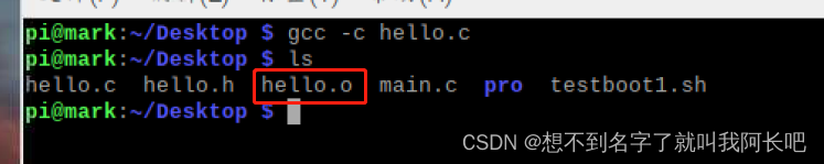
}将.c文件转换至汇编文件*.c
gcc -c hello.c
执行ar命令
格式:
ar -cr libfile.a file.o例如
ar -cr libhello.a hello.o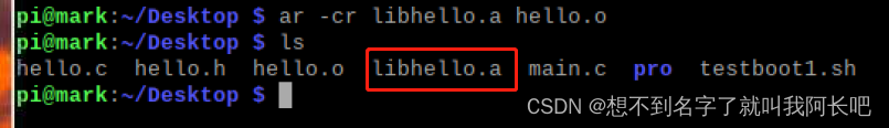 编译文件:
编译文件:
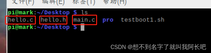
查看当前路径,或者是你想放目录的路径(该死的水印还得截大一点图)
编译
gcc -o main main.c -L/home/pi/Desktop -lhello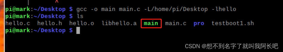
运行

正常
看,我删除了生成的库,可执行文件仍然可以正常执行

2、动态库
一样准备好.c .h 和测试文件
生成动态库:
gcc -fPIC -shared -o libhello.so hello.c
告知连接器库的搜索路径:就是你库所放的路径
export LD_LIBRARY_PATH="/home/pi/Desktop"
编译生成可执行文件:
gcc -o main main.c -L/home/pi/Desktop -lhello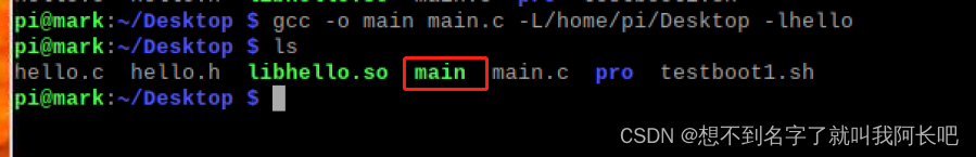
运行看一下:

现在修改一下库的内容:
#ifndef __HELLO_C_
#define __HELLO_C_

#include <stdio.h>
#include "hello.h"

void hello_out()
{
    printf("hello mark_h_1\n");
    printf("hello mark_h_2\n");

}


#endif
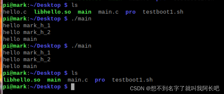
重新生成动态库:
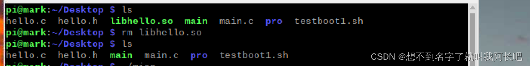
gcc -fPIC -shared -o libhello.so hello.c运行可执行文件:发现结果已经改变

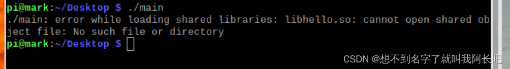
现在将生成的库删掉:再运行文件,出现错误
如果我删除的事hello.c 与hello.h文件,而保留库则发现可执行文件仍然正常运行
十、开机自启


 1895
1895

 被折叠的 条评论
为什么被折叠?
被折叠的 条评论
为什么被折叠?
 到【灌水乐园】发言


