


文章目录
在嵌入式开发中,经常会涉及到图像数据的传输与处理。本文将介绍如何使用 ESP32 采集图像数据并通过串口发送,以及使用 Python 程序接收和保存这些图像数据。
ESP32 端代码
首先,在 ESP32 的代码中,我们引入了相关的库和头文件,包括 esp_camera.h、FS.h、SD.h 和 SPI.h 等。
通过定义一些变量来记录拍摄时间、文件计数器以及相机和 SD 卡的状态。
关键的函数 photo_save 用于拍摄照片、保存到 SD 卡,并通过串口发送图像数据。在发送时,先发送 START_JPEG 标记,然后发送图像数据,最后发送 END_JPEG 标记。
writeFile 函数用于将图像数据写入 SD 卡文件。
在 setup 函数中,进行了串口、相机和 SD 卡的初始化设置。
loop 函数中,当相机和 SD 卡都准备好时,每隔一分钟拍摄一张照片并进行处理。
#include "esp_camera.h"
#include "FS.h"
#include "SD.h"
#include "SPI.h"

#define CAMERA_MODEL_XIAO_ESP32S3 // Has PSRAM
#include "camera_pins.h"

unsigned long lastCaptureTime = 0; // Last shooting time
int imageCount = 1;                // File Counter
bool camera_sign = false;          // Check camera status
bool sd_sign = false;              // Check sd status

// 新增UART相关配置
#define UART_TX_PIN    GPIO_NUM_43   // 根据实际硬件连接修改
#define UART_RX_PIN    GPIO_NUM_44   // 根据实际硬件连接修改
#define UART_BAUD_RATE 115200

// Save pictures to SD card and send via UART
void photo_save(const char * fileName) {
  // Take a photo
  camera_fb_t *fb = esp_camera_fb_get();
  if (!fb) {
    Serial.println("Failed to get camera frame buffer");
    return;
  }

  // Save photo to file
  writeFile(SD, fileName, fb->buf, fb->len);

  // Send image data via UART
  // Serial1.write((uint8_t *)fb->buf, fb->len); // 发送图像数据
  // Serial1.write("START_JPEG");
  // Serial1.write((uint8_t *)fb->buf, fb->len);
  // Serial1.write("END_JPEG");
  Serial1.write((uint8_t *)"START_JPEG", 10); // 发送 START_JPEG 标记
  Serial1.write((uint8_t *)fb->buf, fb->len); // 发送图像数据
  Serial1.write((uint8_t *)"END_JPEG", 8);    // 发送 END_JPEG 标记

  Serial.println("Photo saved to file and sent via UART");

  // Release image buffer
  esp_camera_fb_return(fb);
}

// SD card write file
void writeFile(fs::FS &fs, const char * path, uint8_t * data, size_t len){
    Serial.printf("Writing file: %s\r\n", path);
    File file = fs.open(path, FILE_WRITE);
    if(!file){
        Serial.println("Failed to open file for writing");
        return;
    }
    if(file.write(data, len) == len){
        Serial.println("File written");
    } else {
        Serial.println("Write failed");
    }
    file.close();
}

void setup() {
  Serial.begin(115200);
  while(!Serial); // When the serial monitor is turned on, the program starts to execute
  Serial1.begin(UART_BAUD_RATE, SERIAL_8N1, UART_RX_PIN, UART_TX_PIN); // 使用GPIO44(RX), GPIO43(TX)

  camera_config_t config;
  config.ledc_channel = LEDC_CHANNEL_0;
  config.ledc_timer = LEDC_TIMER_0;
  config.pin_d0 = Y2_GPIO_NUM;
  config.pin_d1 = Y3_GPIO_NUM;
  config.pin_d2 = Y4_GPIO_NUM;
  config.pin_d3 = Y5_GPIO_NUM;
  config.pin_d4 = Y6_GPIO_NUM;
  config.pin_d5 = Y7_GPIO_NUM;
  config.pin_d6 = Y8_GPIO_NUM;
  config.pin_d7 = Y9_GPIO_NUM;
  config.pin_xclk = XCLK_GPIO_NUM;
  config.pin_pclk = PCLK_GPIO_NUM;
  config.pin_vsync = VSYNC_GPIO_NUM;
  config.pin_href = HREF_GPIO_NUM;
  config.pin_sscb_sda = SIOD_GPIO_NUM;
  config.pin_sscb_scl = SIOC_GPIO_NUM;
  config.pin_pwdn = PWDN_GPIO_NUM;
  config.pin_reset = RESET_GPIO_NUM;
  config.xclk_freq_hz = 20000000;
  config.frame_size = FRAMESIZE_UXGA;
  config.pixel_format = PIXFORMAT_JPEG; // for streaming
  config.grab_mode = CAMERA_GRAB_WHEN_EMPTY;
  config.fb_location = CAMERA_FB_IN_PSRAM;
  config.jpeg_quality = 12;
  config.fb_count = 1;

  // if PSRAM IC present, init with UXGA resolution and higher JPEG quality
  //                      for larger pre-allocated frame buffer.
  if(config.pixel_format == PIXFORMAT_JPEG){
    if(psramFound()){
      config.jpeg_quality = 10;
      config.fb_count = 2;
      config.grab_mode = CAMERA_GRAB_LATEST;
    } else {
      // Limit the frame size when PSRAM is not available
      config.frame_size = FRAMESIZE_SVGA;
      config.fb_location = CAMERA_FB_IN_DRAM;
    }
  } else {
    // Best option for face detection/recognition
    config.frame_size = FRAMESIZE_240X240;
#if CONFIG_IDF_TARGET_ESP32S3
    config.fb_count = 2;
#endif
  }

  // camera init
  esp_err_t err = esp_camera_init(&config);
  if (err != ESP_OK) {
    Serial.printf("Camera init failed with error 0x%x", err);
    return;
  }

  camera_sign = true; // Camera initialization check passes

  // Initialize SD card
  if(!SD.begin(21)){
    Serial.println("Card Mount Failed");
    return;
  }
  uint8_t cardType = SD.cardType();
  // Determine if the type of SD card is available
  if(cardType == CARD_NONE){
    Serial.println("No SD card attached");
    return;
  }
  Serial.print("SD Card Type: ");
  if(cardType == CARD_MMC){
    Serial.println("MMC");
  } else if(cardType == CARD_SD){
    Serial.println("SDSC");
  } else if(cardType == CARD_SDHC){
    Serial.println("SDHC");
  } else {
    Serial.println("UNKNOWN");
  }
  sd_sign = true; // sd initialization check passes
  Serial.println("Photos will begin in one minute, please be ready.");
}

void loop() {
  // Camera & SD available, start taking pictures
  if(camera_sign && sd_sign){
    // Get the current time
    unsigned long now = millis();

    // If it has been more than 1 minute since the last shot, take a picture and save it to the SD card
    if ((now - lastCaptureTime) >= 6000) {
      char filename[32];
      sprintf(filename, "/image%d.jpg", imageCount);
      photo_save(filename);
      Serial.printf("Saved picture: %s\r\n", filename);
      Serial.println("Photos will begin in one minute, please be ready.");
      imageCount++;
      lastCaptureTime = now;
    }
  }
}
Python 端代码
在 Python 代码中,首先配置串口参数,包括端口、波特率和超时时间。
定义了图像的起始和结束标记。
通过 serial.Serial 打开串口。
image_data 用于存储图像数据缓冲区。
save_image 函数用于将接收到的图像数据保存为文件。
read_serial 函数不断从串口读取数据,将数据追加到缓冲区,然后检查是否接收到完整的图像数据,提取并保存图像,清除已处理的数据。
import serial
import time

# 配置串口参数
SERIAL_PORT = 'COM7'  # 根据实际连接修改
BAUD_RATE = 115200    # 波特率,与 Arduino 的 UART_BAUD_RATE 一致
TIMEOUT = 3           # 超时时间(秒)

# 图像起始和结束标记
START_MARKER = b"START_JPEG"
END_MARKER = b"END_JPEG"

# 打开串口
try:
    ser = serial.Serial(SERIAL_PORT, BAUD_RATE, timeout=TIMEOUT) # 设置buffer很大
    print(f"Serial port {SERIAL_PORT} opened successfully.")
except Exception as e:
    print(f"Failed to open serial port: {e}")
    exit(1)

# 图像数据缓冲区
image_data = bytearray()

# 文件计数器
file_count = 1

def save_image(data):
    """将接收到的图像数据保存为文件"""
    global file_count
    filename = f"received_image_{file_count}.jpg"
    with open(filename, "wb") as f:
        f.write(data)
    print(f"Image saved as {filename}")
    file_count += 1

def read_serial():
    """从串口读取数据并处理"""
    global image_data
    try:
        while True:
            # 读取串口数据
            chunk = ser.read(ser.in_waiting or 1)  # 读取当前可用的所有字节
            # 读取串口的所有数据
            if not chunk:
                continue

            # 将数据追加到缓冲区
            image_data.extend(chunk)

            # print(f"Buffer content: {len(image_data)}")

            # 检查是否接收到完整的图像数据
            while True:
                start_index = image_data.find(START_MARKER)  # 查找起始标记
                end_index = image_data.find(END_MARKER)      # 查找结束标记

                # 如果start_index > end_index,说明开始的图像数据被截断,直接丢弃
                if start_index != -1 and end_index != -1 and start_index > end_index:
                    print(f"invaild data, discarding, from {start_index} start to {end_index} end")
                    image_data = image_data[start_index:]
                    start_index = 0
                    end_index = -1
                    t1 = time.time()

                # 提取图像
                if start_index != -1 and end_index != -1 and end_index > start_index:
                    # 提取完整的 JPEG 数据(去掉起始和结束标记)
                    jpeg_start = start_index + len(START_MARKER)
                    jpeg_end = end_index
                    complete_image = image_data[jpeg_start:jpeg_end]

                    # 保存图像
                    save_image(complete_image)

                    print(f"Received complete image, size: {len(complete_image)}, cost time: {1000*(time.time() - t1):.2f} ms")

                    # 清除已处理的数据(包括 START_JPEG 之前的所有数据)
                    image_data = image_data[end_index + len(END_MARKER):]
                    start_index = -1
                    end_index = -1
                    t1 = time.time()  # 重置计时器
                else:
                    break

    except KeyboardInterrupt:
        print("Program terminated by user.")
    finally:
        ser.close()
        print("Serial port closed.")

if __name__ == "__main__":
    print("Waiting for image data from Arduino...")
    read_serial()
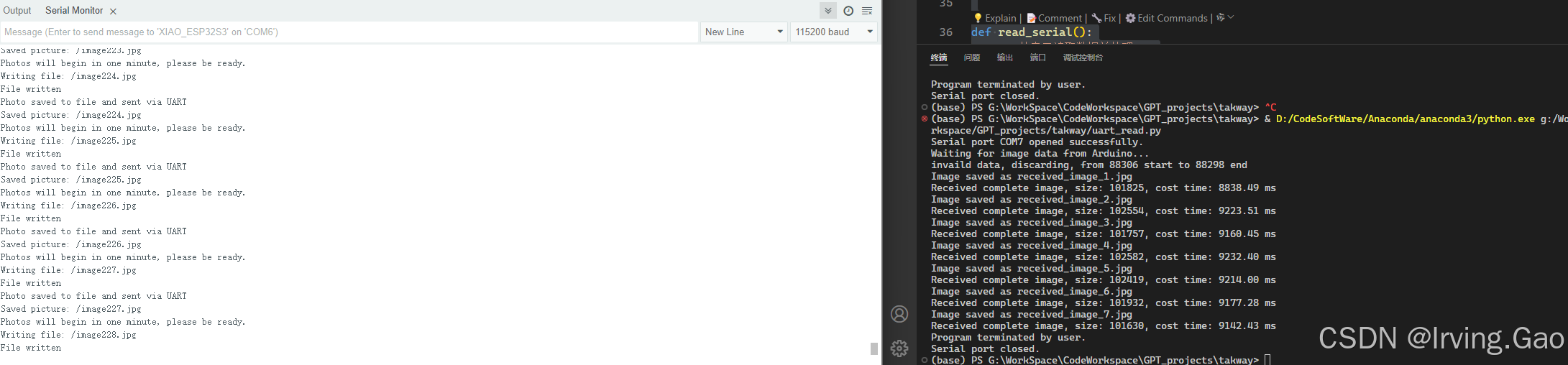
运行结果
Arduino 端输出了照片保存和发送的相关信息。
Python 端成功打开串口,接收到图像数据并保存为文件,输出了保存图像的相关信息,包括文件名、大小和处理时间等。
通过这样的方式,实现了 ESP32 与 Python 之间的图像数据传输和处理,为相关的嵌入式应用提供了一种可行的解决方案。
希望本文能对您在串口图像数据传输方面的开发有所帮助。


 705
705

 被折叠的 条评论
为什么被折叠?
被折叠的 条评论
为什么被折叠?
 到【灌水乐园】发言


