


 本文介绍了如何不使用wiringPi库,而是通过编写Linux驱动来控制GPIO口实现超声波模块的测距功能。驱动分别对应超声波的发射(Trig)和接收(Echo)引脚以及蜂鸣器(Bee)引脚。应用层通过打开和读写设备文件来控制这些引脚,从而实现超声波的触发和距离测量。在应用层测试代码中,展示了两种不同的超声波脉冲发送方法,并根据测量结果控制蜂鸣器的开关状态。
超声波模块
超声波是 4Pin(VCC, Trig, Echo, GND),工作时需要 Trig 发送触发信号,发送超声波信号,回波检测引脚 Echo 接收超声波返回信号。
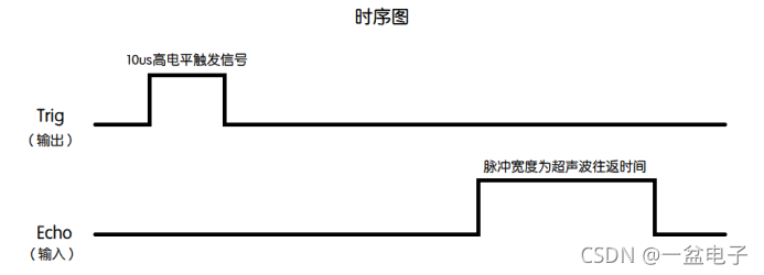
工作过程:
1、Trig 设置成输出模式,给至少 10us 的高电平信号。
2、Echo设置成输入模式,等待有信号返回,当检测到一个高电平,高电平持续的时间就是超声波从发射到返回的时间,测试距离=(高电平时间*声速(340m/s))/2。
基于wiringPi库的超声波检测程序
#include "wiringPi.h"
#include <stdio.h>
#include <sys/time.h>
#define Trig    4
#define Echo    5
#define Bee     7

void ultraInit(void)
{

    pinMode(Echo, INPUT);
    pinMode(Trig, OUTPUT);
    pinMode(Bee,OUTPUT);
}

float disMeasure(void)
{

    struct timeval tv1;  //timeval是time.h中的预定义结构体 其中包含两个一个是秒>,一个是微秒
    /*
    struct timeval
    {
        time_t tv_sec;  //Seconds.
        suseconds_t tv_usec;  //Microseconds.
    };
    */

    struct timeval tv2;
    long start, stop;
    float dis;

    digitalWrite(Trig, LOW);
    delayMicroseconds(2);

    digitalWrite(Trig, HIGH);
    delayMicroseconds(10);      //发出超声波脉冲
    digitalWrite(Trig, LOW);

    while(!(digitalRead(Echo) == 1));
    gettimeofday(&tv1, NULL);           //获取当前时间 开始接收到返回信号的时候

    while(!(digitalRead(Echo) == 0));
    gettimeofday(&tv2, NULL);           //获取当前时间  最后接收到返回信号的时>候
    /*
    int gettimeofday(struct timeval *tv, struct timezone *tz);
    The functions gettimeofday() and settimeofday() can get and set the time as well as a timezone.
    The use of the timezone structure is obsolete; the tz argument should normally be specified as NULL.
    */
    start = tv1.tv_sec * 1000000 + tv1.tv_usec;   //微秒级的时间
    stop  = tv2.tv_sec * 1000000 + tv2.tv_usec;

    dis = (float)(stop - start) / 1000000 * 34000 / 2;  //计算时间差求出距离

    return dis;
}

int main(void)
{

    float dis;

    if(wiringPiSetup() == -1){
    //如果初始化失败,就输出错误信息 程序初始化时务>必进行
        printf("setup wiringPi failed !");
        return -1;
    }

    ultraInit();
    digitalWrite(Bee,HIGH);
    while(1){

        dis = disMeasure();
        printf("distance = %0.2f cm\n",dis);
        if(dis<10)
        {

                digitalWrite(Bee,LOW);
        }
        else
        {

                digitalWrite(Bee,HIGH);
        }
        delay(1000);
    }

    return 0;
}
既然学了设备驱动,就任性一回,不用wiringPi库的函数,自己写驱动控制I/O口。
上一节只对pin4设置输出模式,控制输出高/低电平。这节对代码进行修改,pin17为发射引脚Trig,设置为输出模式。pin27为接收引脚Echo,设置为输入模式。pin4接蜂鸣器模块的信号线,设置为输出模式。
一、知识补充
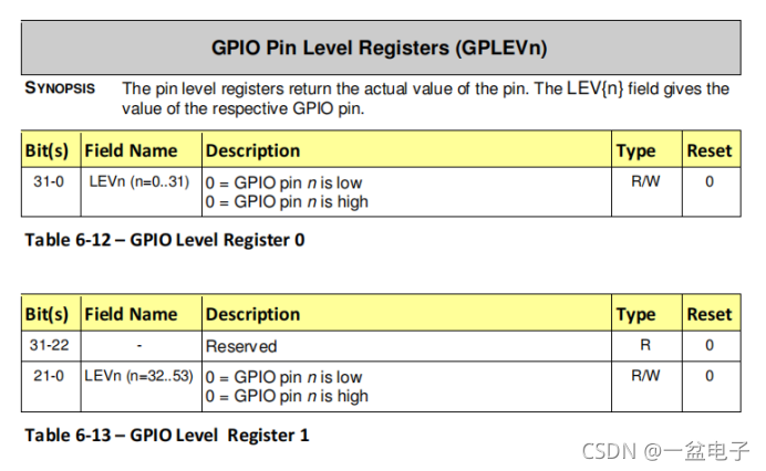
1、寄存器
GPLEVn (物理地址:0x3F200034) 检测I/O口:高/低电平
2、内核函数
copy_to_user函数
unsigned long copy_to_user(void *to, const void *from, unsigned long n)
to:用户空间指针
from:内核空间的指针
n:将要拷贝数据的字节数
返回:成功返回0,失败返回没有拷贝成功的数据字节数。
二、驱动代码
1、pin27–> Echo引脚
//文件pin27driver.c
#include <linux/fs.h>//file_operation声明
#include <linux/module.h>//module_init module_exit声明
#include <linux/init.h>//_init _exit声明
#include <linux/device.h>//class device 声明
#include <linux/uaccess.h>//copy_from_user的头文件
#include <linux/types.h>//设备号 dev_t类型声明
#include <asm/io.h>//ioremap iounmap的头文件

volatile unsigned int *GPFSEL2=NULL;
volatile unsigned int *GPLEV0=NULL;

static struct class *pin27_class;
static struct device *pin27_class_dev;
static dev_t devno;//设备号
static int major=232;//主设备号
static int minor=0;//次设备号
static char *module_name="pin27";//模块名
static int pin27_open(struct inode *inode, struct file *file)
{

	printk("pin27_open\n");//内核的打印函数,和printf函数GPIO初始化:配置pin27引脚为输入模式
	*GPFSEL2&=~(0x07<<21);
	return 0;
}

static ssize_t pin27_read(struct file *filep, char __user *buf, size_t count, loff_t *ppos)
{

	static int iostatus;
	//printk("pin27_read\n");
	iostatus=(*GPLEV0>>27)&0x01;
	if(copy_to_user(buf, (void*)&iostatus, count))
	{
 最低0.47元/天 解锁文章


 1609
1609

 被折叠的 条评论
为什么被折叠?
被折叠的 条评论
为什么被折叠?
 到【灌水乐园】发言


