


一、题目:
要求:
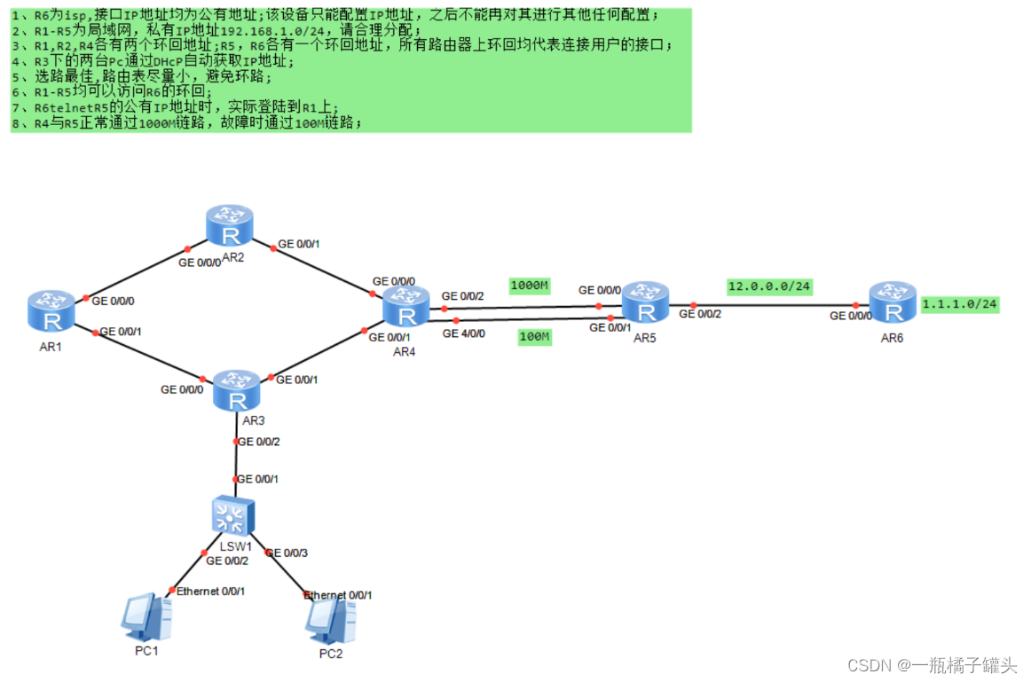
1、R6为isp,接口IP地址均为公有地址;该设备只能配置IP地址,之后不能冉对其进行其他任何配置;
2、R1-R5为局域网,私有IP地址192.168.1.0/24,请合理分配;
3、R1,R2,R4各有两个环回地址;R5,R6各有一个环回地址,所有路由器上环回均代表连接用户的接口;
4、R3下的两台Pc通过DHcP自动获取IP地址;
5、选路最佳,路由表尽量小,避免环路;
6、R1-R5均可以访问R6的环回;
7、R6telnetR5的公有IP地址时,实际登陆到R1上;
8、R4与R5正常通过1000M链路,故障时通过100M链路;
实验分析:
1.要求分析:
从实验拓扑结构可知,R1-R5为内网(私网),R6为外网(公网),R3下的PC端均需要用DHCP自动获取,R1-R5之间的链路总共有6条,每一条链路均需要一条网段 ,R1、R2、R4、R5均拥有环回接口,每一个环回都需要配一个网段,并且部分环回还需要方便汇总,所以可以将192.168.1.0/24划分为8个网段。为了实现全网可达,静态路由必须手动添加路由。
其中部分路由条目可以由缺省路由代替,并将其指向边界路由,可以达到减少路由条目数量的目的。但是每个路由器上可能会出现路由黑洞,当路由黑洞与缺省路由相遇后一定会出现环路,需要在每一个路由器上手动添加空接口,防止形成环路。当链路正常时走1000M线路,故障时走100M线路,可以修改100M线路的优先级。
2.合理划分IP地址:
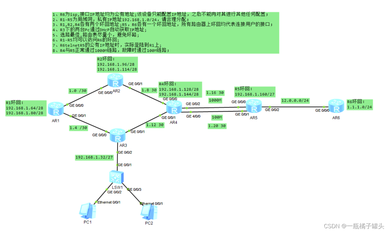
根据分析可知,需要将192.168.1.0/24网段合理的分配为8个网段,具体如下:
192.168.1.0/27
192.168.1.0/30、192.168.1.4/30、192.168.1.8/30、192.168.1.12/30、192.168.1.16/30、 192.168.1.20/30、192.168.1.24/30、192.168.1.28/30(干路)
192.168.1.32/27 (R3下的广播域)
192.168.1.64/27 192.168.1.64/28、192.168.1.80/28(R1环回)
192.168.1.96/27
192.168.1.96/28、192.168.1.114/28(R2环回)
192.168.1.128/27
192.168.1.128/28、192.168.1.144/28(R4环回)
192.168.1.160/27 (R5环回)
192.168.1.196/27
192.168.1.228/27
二、网络拓扑
三、配置:
1.配置IP地址及环回
R1
[R1]int g0/0/0
[R1-GigabitEthernet0/0/0]ip address 192.168.1.1 30
[R1-GigabitEthernet0/0/0]int g0/0/1
[R1-GigabitEthernet0/0/1]ip address 192.168.1.5 30
[R1-GigabitEthernet0/0/1]int l1
[R1-LoopBack1]ip address 192.168.1.65 28
[R1-LoopBack1]int l2
[R1-LoopBack2]ip address 192.168.1.81 28
R2
[R2]int g0/0/0
[R2-GigabitEthernet0/0/0]ip address 192.168.1.2 30
[R2-GigabitEthernet0/0/0]int g0/0/1
[R2-GigabitEthernet0/0/1]ip address 192.168.1.9 30
[R2-GigabitEthernet0/0/1]int l1
[R2-LoopBack1]ip address 192.168.1.97 28
[R2-LoopBack1]int l2
[R2-LoopBack2]ip address 192.168.1.115 28
R3
[R3]int g0/0/0
[R3-GigabitEthernet0/0/0]ip address 192.168.1.6 30
[R3-GigabitEthernet0/0/0]int g0/0/1
[R3-GigabitEthernet0/0/1]ip address 192.168.1.13 30
[R3-GigabitEthernet0/0/1]int g0/0/2
[R3-GigabitEthernet0/0/2]ip address 192.168.1.33 27
R4
[R4]int g0/0/0
[R4-GigabitEthernet0/0/0]ip address 192.168.1.10 30
[R4-GigabitEthernet0/0/0]int g0/0/1
[R4-GigabitEthernet0/0/1]ip address 192.168.1.14 30
[R4-GigabitEthernet0/0/1]int g0/0/2
[R4-GigabitEthernet0/0/2]ip address 192.168.1.17 30
[R4-GigabitEthernet0/0/2]int g4/0/0
[R4-GigabitEthernet4/0/0]ip address 192.168.1.21 30
[R4-GigabitEthernet4/0/0]int l1
[R4-LoopBack1]ip address 192.168.1.129 28
[R4-LoopBack1]int l2
[R4-LoopBack2]ip address 192.168.1.145 28
R5
[R5]int g0/0/0
[R5-GigabitEthernet0/0/0]ip address 192.168.1.18 30
[R5-GigabitEthernet0/0/0]int g0/0/1
[R5-GigabitEthernet0/0/1]ip address 192.168.1.22 30
[R5-GigabitEthernet0/0/1]int g0/0/2
[R5-GigabitEthernet0/0/2]ip address 12.0.0.1 24
[R5-GigabitEthernet0/0/2]int l1
[R5-LoopBack1]ip address 192.168.1.161 27
**R6 **
[R6 isp]int g0/0/0
[R6 isp-GigabitEthernet0/0/0]ip address 12.0.0.2 24
[R6 isp-GigabitEthernet0/0/0]int l1
[R6 isp-LoopBack1]ip address 1.1.1.1 24
2.配置DHCP
通过配置DHCP来自动获取IP地址
R3
[R3]dhcp enable
[R3]ip pool aa
[R3-ip-pool-aa]network 192.168.1.32 mask 27
[R3-ip-pool-aa]gateway-list 192.168.1.33
[R3-ip-pool-aa]dns-list 8.8.8.8
[R3]int g0/0/2
[R3-GigabitEthernet0/0/2]dhcp select global
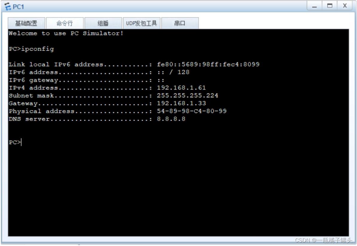
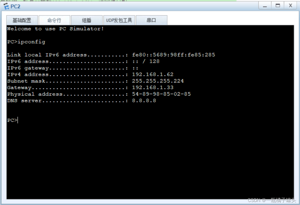
测试:
PC通过DHCP来自动获取IP地址
PC1
PC2
3.配置静态路由
R1
[R1]ip route-static 0.0.0.0 0 192.168.1.2
[R1]ip route-static 0.0.0.0 0 192.168.1.6
[R1]ip route-static 192.168.1.96 27 192.168.1.2
[R1]ip route-static 192.168.1.8 30 192.168.1.2
[R1]ip route-static 192.168.1.32 27 192.168.1.6
[R1]ip route-static 192.168.1.12 30 192.168.1.6
R2
[R2]ip route-static 192.168.1.64 27 192.168.1.1
[R2]ip route-static 192.168.1.4 30 192.168.1.1
[R2]ip route-static 192.168.1.12 30 192.168.1.10
[R2]ip route-static 192.168.1.32 27 192.168.1.1
[R2]ip route-static 192.168.1.32 27 192.168.1.10
R3
[R3]ip route-static 0.0.0.0 0 192.168.1.14
[R3]ip route-static 192.168.1.64 27 192.168.1.5
[R3]ip route-static 192.168.1.0 30 192.168.1.5
[R3]ip route-static 192.168.1.8 30 192.168.1.14
[R3]ip route-static 192.168.1.96 27 192.168.1.5
[R3]ip route-static 192.168.1.96 27 192.168.1.14
R4
[R4]ip route-static 0.0.0.0 0 192.168.1.18
[R4]ip route-static 0.0.0.0 0 192.168.1.22 preference 70
[R4]ip route-static 192.168.1.96 27 192.168.1.9
[R4]ip route-static 192.168.1.0 30 192.168.1.9
[R4]ip route-static 192.168.1.64 27 192.168.1.9
[R4]ip route-static 192.168.1.64 27 192.168.1.13
[R4]ip route-static 192.168.1.4 30 192.168.1.13
[R4]ip route-static 192.168.1.32 27 192.168.1.13
R5
[R5]ip route-static 192.168.1.0 24 192.168.1.17
[R5]ip route-static 192.168.1.0 24 g0/0/2 192.168.1.21

[R5]acl 2000
[R5-acl-basic-2000]rule 5 permit source 192.168.1.0 0.0.0.255
[R5]int g0/0/1
[R5-GigabitEthernet0/0/1]nat outbound 2000
添加空接口
[R1]ip route-static 192.168.1.64 27 NULL 0
[R2]ip route-static 192.168.1.96 27 NULL 0
[R3]ip route-static 192.168.1.32 27 NULL 0
[R4]ip route-static 192.168.1.128 27 NULL 0
[R5]ip route-static 192.168.1.160 27 NULL 0
4.配置Telent
R1
[R1]aaa
[R1-aaa]local-user gxh privilege level 15 password cipher 123456
[R1-aaa]local-user gxh service-type telnet
[R1]user-interface vty 0 4
[R1-ui-vty0-4]authentication-mode aaa
R5
[R5]int g0/0/1
[R5-GigabitEthernet0/0/1]nat server protocol tcp global current-interface 23 inside 192.168.1.1 23


 2036
2036

 被折叠的 条评论
为什么被折叠?
被折叠的 条评论
为什么被折叠?
 到【灌水乐园】发言


