A trip through the Graphics Pipeline 2011, part 4
Welcome back. Last part was about vertex shaders, with some coverage of GPU shader units in general. Mostly, they’re just vector processors, but they have access to one resource that doesn’t exist in other vector architectures: Texture samplers. They’re an integral part of the GPU pipeline and are complicated (and interesting!) enough to warrant their own article, so here goes.
Texture state
Before we start with the actual texturing operations, let’s have a look at the API state that drives texturing. In the D3D11 part, this is composed of 3 distinct parts:
- The sampler state. Filter mode, addressing mode, max anisotropy, stuff like that. This controls how texture sampling is done in a general way.
- The underlying texture resource. This boils down to a pointer to the raw texture bits in memory. The resource also determines whether it’s a single texture or a texture array, what multisample format the texture has (if any), and the physical layout of the texture bits – i.e. at the resource level, it’s not yet decided how the values in memory are to be interpreted exactly, but their memory layout is nailed down.
- The shader resource view (SRV for short). This determines how the texture bits are to be interpreted by the sampler. In D3D10+, the resource view links to the underlying resource, so you never specify the resource explicitly.
Most of the time, you will create a texture resource with a given format, let’s say RGBA, 8 bits per component, and then just create a matching SRV. But you can also create a texture as “8 bits per component, typeless” and then have several different SRVs for the same resource that read the underlying data in different formats, e.g. once as UNORM8_SRGB (unsigned 8-bit value in sRGB space that gets mapped to float 0..1) and once as UINT8 (unsigned 8-bit integer).
Creating the extra SRV seems like an annoying extra step at first, but the point is that this allows the API runtime to do all type checking at SRV creation time; if you get a valid SRV back, that means the SRV and resource formats are compatible, and no further type checking needs to be done while that SRV exists. In other words, it’s all about API efficiency here.
Anyway, at the hardware level, what this boils down to is just a bag of state associated with a texture sampling operation – sampler state, texture/format to use, etc. – that needs to get kept somewhere (see part 2 for an explanation of various ways to manage state in a pipelined architecture). So again, there’s various methods, from “pipeline flush every time any state changes” to “just go completely stateless in the sampler and send the full set along with every texture request”, with various options inbetween. It’s nothing you need to worry about – this is the kind of thing where HW architects whip up a cost-benefit analysis, simulate a few workloads and then take whichever method comes out ahead – but it’s worth repeating: as PC programmer, don’t assume the HW adheres to any particular model.
Don’t assume that texture switches are expensive – they might be fully pipelined with stateless texture samplers so they’re basically free. But don’t assume they’re completely free either – maybe they are not fully pipelined or there’s a cap on the maximum number of different sets of texture states in the pipeline at any given time. Unless you’re on a console with fixed hardware (or you hand-optimize your engine for every generation of graphics HW you’re targeting), there’s just no way to tell. So when optimizing, do the obvious stuff – sort by material where possible to avoid unnecessary state changes and the like – which certainly saves you some API work at the very least, and then leave it at that. Don’t do anything fancy based on any particular model of what the HW is doing, because it can (and will!) change in the blink of an eye between HW generations.
Anatomy of a texture request
So, how much information do we need to send along with a texture sample request? It depends on the texture type and which kind of sampling instruction we’re using. For now, let’s assume a 2D texture. What information do we need to send if we want to do a 2D texture sample with, say, up to 4x anisotropic sampling?
- The 2D texture coordinates – 2 floats, and sticking with the D3D terminology in this series, I’m going to call them u/v and not s/t.
- The partial derivatives of u and v along the screen “x” direction:
,
.
- Similarly, we need the partial derivative in the “y” direction too:
,
.
So, that’s 6 floats for a fairly pedestrian 2D sampling request (of the SampleGrad variety) – probably more than you thought. The 4 gradient values are used both for mipmap selection and to choose the size and shape of the anisotropic filtering kernel. You can also use texture sampling instructions that explicitly specify a mipmap level (in HLSL, that would be SampleLevel) – these don’t need the gradients, just a single value containing the LOD parameter, but they also can’t do anisotropic filtering – the best you’ll get is trilinear! Anyway, let’s stay with those 6 floats for a while. That sure seems like a lot. Do we really need to send them along with every texture request?
The answer is: depends. In everything but Pixel Shaders, the answer is yes, we really have to (if we want anisotropic filtering that is). In Pixel Shaders, turns out we don’t; there’s a trick that allows Pixel Shaders to give you gradient instructions (where you can compute some value and then ask the hardware “what is the approximate screen-space gradient of this value?”), and that same trick can be employed by the texture sampler to get all the required partial derivatives just from the coordinates. So for a PS 2D “sample” instruction, you really only need to send the 2 coordinates which imply the rest, provided you’re willing to do some more math in the sampler units.
Just for kicks: What’s the worst-case number of parameters required for a single texture sample? In the current D3D11 pipeline, it’s a SampleGrad on a Cubemap array. Let’s see the tally:
- 3D texture coordinates – u, v, w: 3 floats.
- Cubemap array index: one int (let’s just bill that at the same cost as a float here).
- Gradient of (u,v,w) in the screen x and y directions: 6 floats.
For a total of 10 values per pixel sampled – that’s 40 bytes if you actually store it like that. Now, you might decide that you don’t need full 32 bits for all of this (it’s probably overkill for the array index and gradients), but it’s still a lot of data to be sending around.
In fact, let’s check what kind of bandwidth we’re talking about here. Let’s assume that most of our textures are 2D (with a few cubemaps thrown in), that most of our texture sampling requests come from the Pixel Shader with little to no texture samples in the Vertex Shader, and that the regular Sample-type requests are the most frequent, followed by SampleLevel (all of this is pretty typical for actual rendering you see in games). That means the average number of 32-bit floats values sent per pixel will be somewhere between 2 (u+v) and 3 (u+v+w / u+v+lod), let’s say 2.5, or 10 bytes.
Assume a medium resolution – say, 1280×720, which is about 0.92 million pixels. How many texture samples does your average game pixel shader have? I’d say at least 3. Let’s say we have a modest amount of overdraw, so during the 3D rendering phase, we touch each pixel on the screen roughly twice. And then we finish it off with a few texture-heavy full-screen passes to do post-processing. That probably adds at least another 6 samples per pixel, taking into account that some of that postprocessing will be done at a lower resolution. Add it all up and we have 0.92 * (3*2 + 6) = about 11 million texture samples per frame, which at 30 fps is about 330 million a second. At 10 bytes per request, that’s 3.3 GB/s just for texture request payloads. Lower bound, since there’s some extra overhead involved (we’ll get to that in a second). Note that I’m *cough* erring “a bit” on the low side with all of these numbers :). An actual modern game on a good DX11 card will run in significantly higher resolution, with more complex shaders than I listed, comparable amount of overdraw or even somewhat less (deferred shading/lighting to the rescue!), higher frame rate, and way more complex postprocessing – go ahead, do a quick back-of-the-envelope calculation how much texture request bandwidth a decent-quality SSAO pass in quarter-resolution with bilateral upsampling takes…
Point being, this whole texture bandwidth thing is not something you can just hand-wave away. The texture samplers aren’t part of the shader cores, they’re separate units some distance away on the chip, and shuffling multiple gigabytes per second around isn’t something that just happens by itself. This is an actual architectural issue – and it’s a good thing we don’t use SampleGrad on Cubemap arrays for everything :)
But who asks for a single texture sample?
The answer is of course: No one. Our texture requests are coming from shader units, which we know process somewhere between 16 and 64 pixels / vertices / control points / … at once. So our shaders won’t be sending individual texture samples, they’ll dispatch a bunch of them at once. This time, I’ll use 16 as the number – simply because the 32 I chose last time is non-square, which just seems weird when talking about 2D texture requests. So, 16 texture requests at once – build that texture request payload, add some command fields at the start so the sampler knows what to do, add some more fields so the sampler knows which texture and sampler state to use (again, see the remarks above on state), and send that off to a texture sampler somewhere.
This will take a while.
No, seriously. Texture samplers have a seriously long pipeline (we’ll soon see why); a texture sampling operation takes way too long for a shader unit to just sit idle for all that time. Again, say it with me: throughput. So what happens is that on a texture sample, a shader unit will just quietly switch to another thread/batch and do some other work, then switch back a while later when the results are there. Works just fine as long as there’s enough independent work for the shader units to do!
And once the texture coordinates arrive…
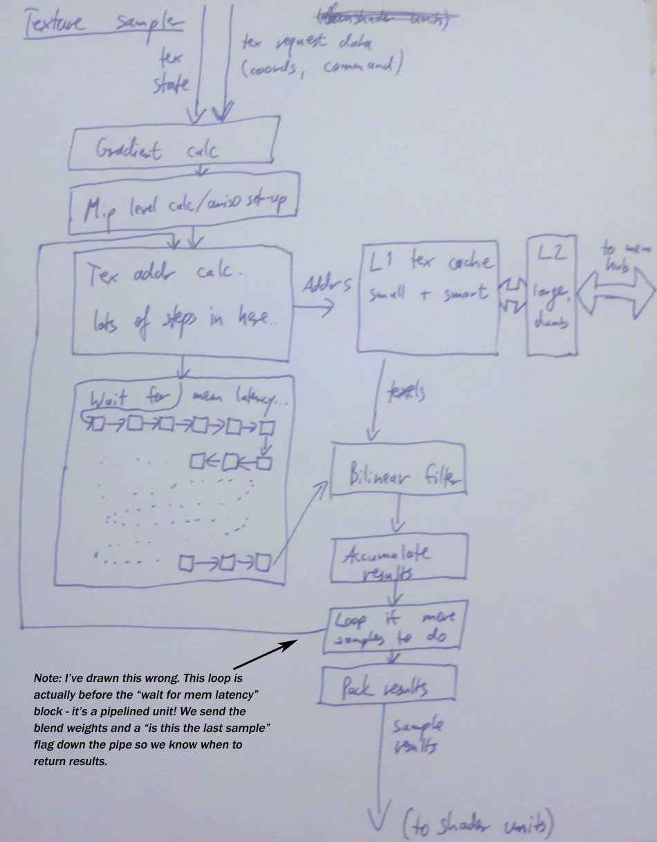
Well, there’s a bunch of computations to be done first: (In here and the following, I’m assuming a simple bilinear sample; trilinear and anisotropic take some more work, see below).
- If this is a
SampleorSampleBias-type request, calculate texture coordinate gradients first. - If no explicit mip level was given, calculate the mip level to be sampled from the gradients and add the LOD bias if specified.
- For each resulting sample position, apply the address modes (wrap / clamp / mirror etc.) to get the right position in the texture to sample from, in normalized [0,1] coordinates.
- If this is a cubemap, we also need to determine which cube face to sample from (based on the absolute values and signs of the u/v/w coordinates), and do a division to project the coordinates onto the unit cube so they are in the [-1,1] interval. We also need to drop one of the 3 coordinates (based on the cube face) and scale/bias the other 2 so they’re in the same [0,1] normalized coordinate space we have for regular texture samples.
- Next, take the [0,1] normalized coordinates and convert them into fixed-point pixel coordinates to sample from – we need some fractional bits for the bilinear interpolation.
- Finally, from the integer x/y/z and texture array index, we can now compute the address to read texels from. Hey, at this point, what’s a few more multiplies and adds among friends?
If you think it sounds bad summed up like that, let me take remind you that this is a simplified view. The above summary doesn’t even cover fun issues such as texture borders or sampling cubemap edges/corners. Trust me, it may sound bad now, but if you were to actually write out the code for everything that needs to happen here, you’d be positively horrified. Good thing we have dedicated hardware to do it for us. :) Anyway, we now have a memory address to get data from. And wherever there’s memory addresses, there’s a cache or two nearby.
Texture cache
Everyone seems to be using a two-level texture cache these days. The second-level cache is a completely bog-standard cache that happens to cache memory containing texture data. The first-level cache is not quite as standard, because it’s got additional smarts. It’s also smaller than you probably expect – on the order of 4-8kb per sampler. Let’s cover the size first, because it tends to come as a surprise to most people.
The thing is this: Most texture sampling is done in Pixel Shaders with mip-mapping enabled, and the mip level for sampling is specifically chosen to make the screen pixel:texel ratio roughly 1:1 – that’s the whole point. But this means that, unless you happen to hit the exact same location in a texture again and again, each texture sampling operation will miss about 1 texel on average – the actual measured value with bilinear filtering is around 1.25 misses/request (if you track pixels individually). This value stays more or less unchanged for a long time even as you change texture cache size, and then drops dramatically as soon as your texture cache is large enough to contain the whole texture (which usually is between a few hundred kilobytes and several megabytes, totally unrealistic sizes for a L1 cache).
Point being, any texture cache whatsoever is a massive win (since it drops you down from about 4 memory accesses per bilinear sample down to 1.25). But unlike with a CPU or shared memory for shader cores, there’s very little gain in going from say 4k of cache to 16k; we’re streaming larger texture data through the cache no matter what.
Second point: Because of the 1.25 misses/sample average, texture sampler pipelines need to be long enough to sustain a full read from memory per sample without stalling. Let me phrase that differently: texture sampler pipes are long enough to not stall for a memory read even though it takes 400-800 cycles. That’s one seriously long pipeline right there – and it really is a pipeline in the literal sense, handing data from one pipeline register to the next for a few hundred cycles without any processing until the memory read is completed.
So, small L1 cache, long pipeline. What about the “additional smarts”? Well, there’s compressed texture formats. The ones you see on PC – S3TC aka DXTC aka BC1-3, then BC4 and 5 which were introduced with D3D10 and are just variations on DXT, and finally BC6H and 7 which were introduced with D3D11 – are all block-based methods that encode blocks of 4×4 pixels individually. If you decode them during texture sampling, that means you need to be able to decode up to 4 such blocks (if your 4 bilinear sample points happen to land in the worst-case configuration of straddling 4 blocks) per cycle and get a single pixel from each. That, frankly, just sucks. So instead, the 4×4 blocks are decoded when it’s brought into the L1 cache: in the case of BC3 (aka DXT5), you fetch one 128-bit block from texture L2, and then decode that into 16 pixels in the texture cache. And suddenly, instead of having to partially decode up to 4 blocks per sample, you now only need to decode 1.25/(4*4) = about 0.08 blocks per sample, at least if your texture access patterns are coherent enough to hit the other 15 pixels you decoded alongside the one you actually asked for :). Even if you only end up using part of it before it goes out of L1 again, that’s still a massive improvement. Nor is this technique limited to DXT blocks; you can handle most of the differences between the >50 different texture formats required by D3D11 in your cache fill path, which is hit about a third as often as the actual pixel read path – nice. For example, things like UNORM sRGB textures can be handled by converting the sRGB pixels into a 16-bit integer/channel (or 16-bit float/channel, or even 32-bit float if you want) in the texture cache. Filtering then operates on that, properly, in linear space. Mind that this does end up increasing the footprint of texels in the L1 cache, so you might want to increase L1 texture size; not because you need to cache more texels, but because the texels you cache are fatter. As usual, it’s a trade-off.
Filtering
And at this point, the actual bilinear filtering process is fairly straightforward. Grab 4 samples from the texture cache, use the fractional positions to blend between them. That’s a few more of our usual standby, the multiply-accumulate unit. (Actually a lot more – we’re doing this for 4 channels at the same time…)
Trilinear filtering? Two bilinear samples and another linear interpolation. Just add some more multiply-accumulates to the pile.
Anisotropic filtering? Now that actually takes some extra work earlier in the pipe, roughly at the point where we originally computed the mip-level to sample from. What we do is look at the gradients to determine not just the area but also the shape of a screen pixel in texel space; if it’s roughly as wide as it is high, we just do a regular bilinear/trilinear sample, but if it’s elongated in one direction, we do several samples across that line and blend the results together. This generates several sample positions, so we end up looping through the full bilinear/trilinear pipeline several times, and the actual way the samples are placed and their relative weights are computed is a closely guarded secret for each hardware vendor; they’ve been hacking at this problem for years, and by now both converged on something pretty damn good at reasonable hardware cost. I’m not gonna speculate what it is they’re doing; truth be told, as a graphics programmer, you just don’t need to care about the underlying anisotropic filtering algorithm as long as it’s not broken and produces either terrible artifacts or terrible slowdowns.
Anyway, aside from the setup and the sequencing logic to loop over the required samples, this does not add a significant amount of computation to the pipe. At this point we have enough multiply-accumulate units to compute the weighted sum involved in anisotropic filtering without a lot of extra hardware in the actual filtering stage. :)
Texture returns
And now we’re almost at the end of the texture sampler pipe. What’s the result of all this? Up to 4 values (r, g, b, a) per texture sample requested. Unlike texture requests where there’s significant variation in the size of requests, here the most common case by far is just the shader consuming all 4 values. Mind you, sending 4 floats back is nothing to sneeze at from a bandwidth point of view, and again you might want to shave bits in some case. If your shader is sampling a 32-bit float/channel texture, you’d better return 32-bit floats, but if it’s reading a 8-bit UNORM SRGB texture, 32 bit returns are just overkill, and you can save bandwidth by using a smaller format on the return path.
And that’s it – the shader unit now has its texture sampling results back and can resume working on the batch you submitted – which concludes this part. See you again in the next installment, when I talk about the work that needs to be done before we can actually start rasterizing primitives. Update: And here’s a picture of the texture sampling pipeline, including an amusing mistake that I’ve fixed in post like a pro!
The usual post-script
This time, no big disclaimers. The numbers I mentioned in the bandwidth example are honestly just made up on the spot since I couldn’t be arsed to look up some actual figures for current games :), but other than that, what I describe here should be pretty close to what’s on your GPU right now, even though I hand-waved past some of the corner cases in filtering and such (mainly because the details are more nauseating than they are enlightening).
As for texture L1 cache containing decompressed texture data, to the best of my knowledge this is accurate for current hardware. Some older HW would keep some formats compressed even in L1 texture cache, but because of the “1.25 misses/sample for a large range of cache sizes” rule, that’s not a big win and probably not worth the complexity. I think that stuff’s all gone now.
An interesting bit are embedded/power-optimized graphics chips, e.g. PowerVR; I’ll not go into these kinds of chips much in this series since my focus here is on the high-performance parts you see in PCs, but I have some notes about them in the comments for previous parts if you’re interested. Anyway, the PVR chips have their own texture compression format that’s not block-based and very tightly integrated with their filtering hardware, so I would assume that they do keep their textures compressed even in L1 texture cache (actually, I don’t know if they even have a second cache level!). It’s an interesting method and probably at a fairly sweet spot in terms of useful work done per area and energy consumed. But I think the “depack to L1 cache” method gives higher throughput overall, and as I can’t mention often enough, it’s all about throughput on high-end PC GPUs :)
 133


 扫一扫


 被折叠的 条评论
为什么被折叠?
 到【灌水乐园】发言