A trip through the Graphics Pipeline 2011, part 2
Not so fast.
In the previous part I explained the various stages that your 3D rendering commands go through on a PC before they actually get handed off to the GPU; short version: it’s more than you think. I then finished by name-dropping the command processor and how it actually finally does something with the command buffer we meticulously prepared. Well, how can I say this – I lied to you. We’ll indeed be meeting the command processor for the first time in this installment, but remember, all this command buffer stuff goes through memory – either system memory accessed via PCI Express, or local video memory. We’re going through the pipeline in order, so before we get to the command processor, let’s talk memory for a second.
The memory subsystem
GPUs don’t have your regular memory subsystem – it’s different from what you see in general-purpose CPUs or other hardware, because it’s designed for very different usage patterns. There’s two fundamental ways in which a GPU’s memory subsystem differs from what you see in a regular machine:
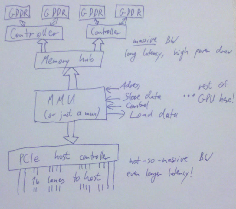
The first is that GPU memory subsystems are fast. Seriously fast. A Core i7 2600K will hit maybe 19 GB/s memory bandwidth – on a good day. With tail wind. Downhill. A GeForce GTX 480, on the other hand, has a total memory bandwidth of close to 180 GB/s – nearly an order of magnitude difference! Whoa.
The second is that GPU memory subsystems are slow. Seriously slow. A cache miss to main memory on a Nehalem (first-generation Core i7) takes about 140 cycles if you divide the memory latency as given by AnandTech by the clock rate. The GeForce GTX 480 I mentioned previously has a memory access latency of 400-800 clocks. So let’s just say that, measured in cycles, the GeForce GTX 480 has a bit more than 4x the average memory latency of a Core i7. Except that Core i7 I just mentioned is clocked at 2.93GHz, whereas GTX 480 shader clock is 1.4 GHz – that’s it, another 2x right there. Woops – again, nearly an order of magnitude difference! Wait, something funny is going on here. My common sense is tingling. This must be one of those trade-offs I keep hearing about in the news!
Yep – GPUs get a massive increase in bandwidth, but they pay for it with a massive increase in latency (and, it turns out, a sizable hit in power draw too, but that’s beyond the scope of this article). This is part of a general pattern – GPUs are all about throughput over latency; don’t wait for results that aren’t there yet, do something else instead!
That’s almost all you need to know about GPU memory, except for one general DRAM tidbit that will be important later on: DRAM chips are organized as a 2D grid – both logically and physically. There’s (horizontal) row lines and (vertical) column lines. At each intersection between such lines is a transistor and a capacitor; if at this point you want to know how to actually build memory from these ingredients, Wikipedia is your friend. Anyway, the salient point here is that the address of a location in DRAM is split into a row address and a column address, and DRAM reads/writes internally always end up accessing all columns in the given row at the same time. What this means is that it’s much cheaper to access a swath of memory that maps to exactly one DRAM row than it is to access the same amount of memory spread across multiple rows. Right now this may seem like just a random bit of DRAM trivia, but this will become important later on; in other words, pay attention: this will be on the exam. But to tie this up with the figures in the previous paragraphs, just let me note that you can’t reach those peak memory bandwidth figures above by just reading a few bytes all over memory; if you want to saturate memory bandwidth, you better do it one full DRAM row at a time.
The PCIe host interface
From a graphics programmer standpoint, this piece of hardware isn’t super-interesting. Actually, the same probably goes for a GPU hardware architect too. The thing is, you still start caring about it once it’s so slow that it’s a bottleneck. So what you do is get good people on it to do it properly, to make sure that doesn’t happen. Other than that, well, this gives the CPU read/write access to video memory and a bunch of GPU registers, the GPU read/write access to (a portion of) main memory, and everyone a headache because the latency for all these transactions is even worse than memory latency because the signals have to go out of the chip, into the slot, travel a bit across the mainboard then get to someplace in the CPU about a week later (or that’s how it feels compared to the CPU/GPU speeds anyway). The bandwidth is decent though – up to about 8GB/s (theoretical) peak aggregate bandwidth across the 16-lane PCIe 2.0 connections that most GPUs use right now, so between half and a third of the aggregate CPU memory bandwidth; that’s a usable ratio. And unlike earlier standards like AGP, this is a symmetrical point-to-point link – that bandwidth goes both directions; AGP had a fast channel from the CPU to the GPU, but not the other way round.
Some final memory bits and pieces
Honestly, we’re very very close to actually seeing 3D commands now! So close you can almost taste them. But there’s one more thing we need to get out of the way first. Because now we have two kinds of memory – (local) video memory and mapped system memory. One is about a day’s worth of travel to the north, the other is a week’s journey to the south along the PCI Express highway. Which road do we pick?
The easiest solution: Just add an extra address line that tells you which way to go. This is simple, works just fine and has been done plenty of times. Or maybe you’re on a unified memory architecture, like some game consoles (but not PCs). In that case, there’s no choice; there’s just the memory, which is where you go, period. If you want something fancier, you add a MMU (memory management unit), which gives you a fully virtualized address space and allows you to pull nice tricks like having frequently accessed parts of a texture in video memory (where they’re fast), some other parts in system memory, and most of it not mapped at all – to be conjured up from thing air, or, more usually, by a magic disk read that will only take about 50 years or so – and by the way, this is not hyperbole; if you stay with the “memory access = 1 day” metaphor, that’s really how long a single HD read takes. A quite fast one at that. Disks suck. But I digress.
So, MMU. It also allows you to defragment your video memory address space without having to actually copy stuff around when you start running out of video memory. Nice thing, that. And it makes it much easier to have multiple processes share the same GPU. It’s definitely allowed to have one, but I’m not actually sure if it’s a requirement or not, even though it’s certainly really nice to have (anyone care to help me out here? I’ll update the article if I get clarification on this, but tbh right now I just can’t be arsed to look it up). Anyway, a MMU/virtual memory is not really something you can just add on the side (not in an architecture with caches and memory consistency concerns anyway), but it really isn’t specific to any particular stage – I have to mention it somewhere, so I just put it here.
There’s also a DMA engine that can copy memory around without having to involve any of our precious 3D hardware/shader cores. Usually, this can at least copy between system memory and video memory (in both directions). It often can also copy from video memory to video memory (and if you have to do any VRAM defragmenting, this is a useful thing to have). It usually can’t do system memory to system memory copies, because this is a GPU, not a memory copying unit – do your system memory copies on the CPU where they don’t have to pass through PCIe in both directions!
Update: I’ve drawn a picture (link since this layout is too narrow to put big diagrams in the text). This also shows some more details – by now your GPU has multiple memory controllers, each of which controls multiple memory banks, with a fat hub in the front. Whatever it takes to get that bandwidth. :)
Okay, checklist. We have a command buffer prepared on the CPU. We have the PCIe host interface, so the CPU can actually tell us about this, and write its address to some register. We have the logic to turn that address into a load that will actually return data – if it’s from system memory it goes through PCIe, if we decide we’d rather have the command buffer in video memory, the KMD can set up a DMA transfer so neither the CPU nor the shader cores on the GPU need to actively worry about it. And then we can get the data from our copy in video memory through the memory subsystem. All paths accounted for, we’re set and finally ready to look at some commands!
At long last, the command processor!
Our discussion of the command processor starts, as so many things do these days, with a single word:
“Buffering…”
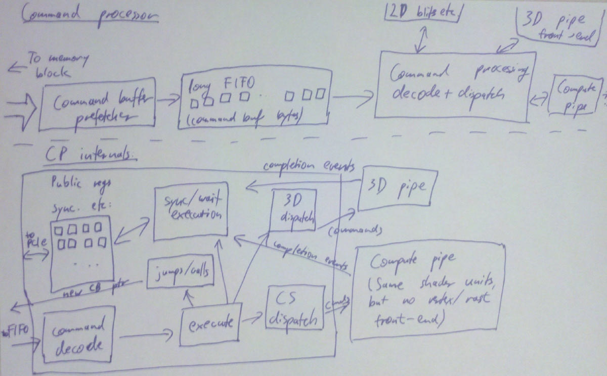
As mentioned above, both of our memory paths leading up to here are high-bandwidth but also high-latency. For most later bits in the GPU pipeline, the method of choice to work around this is to run lots of independent threads. But in this case, we only have a single command processor that needs to chew through our command buffer in order (since this command buffer contains things such as state changes and rendering commands that need to be executed in the right sequence). So we do the next best thing: Add a large enough buffer and prefetch far enough ahead to avoid hiccups.
From that buffer, it goes to the actual command processing front end, which is basically a state machine that knows how to parse commands (with a hardware-specific format). Some commands deal with 2D rendering operations – unless there’s a separate command processor for 2D stuff and the 3D frontend never even sees it. Either way, there’s still dedicated 2D hardware hidden on modern GPUs, just as there’s a VGA chip somewhere on that die that still supports text mode, 4-bit/pixel bit-plane modes, smooth scrolling and all that stuff. Good luck finding any of that on the die without a microscope. Anyway, that stuff exists, but henceforth I shall not mention it again. :) Then there’s commands that actually hand some primitives to the 3D/shader pipe, woo-hoo! I’ll take about them in upcoming parts. There’s also commands that go to the 3D/shader pipe but never render anything, for various reasons (and in various pipeline configurations); these are up even later.
Then there’s commands that change state. As a programmer, you think of them as just changing a variable, and that’s basically what happens. But a GPU is a massively parallel computer, and you can’t just change a global variable in a parallel system and hope that everything works out OK – if you can’t guarantee that everything will work by virtue of some invariant you’re enforcing, there’s a bug and you will hit it eventually. There’s several popular methods, and basically all chips use different methods for different types of state.
- Whenever you change a state, you require that all pending work that might refer to that state be finished (i.e. basically a partial pipeline flush). Historically, this is how graphics chips handled most state changes – it’s simple and not that costly if you have a low number of batches, few triangles and a short pipeline. Alas, batch and triangle counts have gone up and pipelines have gotten long, so the cost for this type of approach has shot up. It’s still alive and kicking for stuff that’s either changed infrequently (a dozen partial pipeline flushes aren’t that big a deal over the course of a whole frame) or just too expensive/difficult to implement with more specific schemes though.
- You can make hardware units completely stateless. Just pass the state change command through up to the stage that cares about it; then have that stage append the current state to everything it sends downstream, every cycle. It’s not stored anywhere – but it’s always around, so if some pipeline stage wants to look at a few bits in the state it can, because they’re passed in (and then passed on to the next stage). If your state happens to be just a few bits, this isn’t fairly cheap and practical. If it happens to be the full set of active textures along with texture sampling state, not so much.
- Sometimes storing just one copy of the state and having to flush every time that stage changes serializes things too much, but things would really be fine if you had two copies (or maybe four?) so your state-setting frontend could get a bit ahead. Say you have enough registers (“slots”) to store two versions of every state, and some active job references slot 0. You can safely modify slot 1 without stopping that job, or otherwise interfering with it at all. Now you don’t need to send the whole state around through the pipeline – only a single bit per command that selects whether to use slot 0 or 1. Of course, if both slot 0 and 1 are busy by the time a state change command is encountered, you still have to wait, but you can get one step ahead. The same technique works with more than two slots.
- For some things like sampler or
textureShader Resource View state, you could be setting very large numbers of them at the same time, but chances are you aren’t. You don’t want to reserve state space for 2*128 active textures just because you’re keeping track of 2 in-flight state sets so you might need it. For such cases, you can use a kind of register renaming scheme – have a pool of 128 physical texture descriptors. If someone actually needs 128 textures in one shader, then state changes are gonna be slow. (Tough break). But in the more likely case of an app using less than 20 textures, you have quite some headroom to keep multiple versions around.
This is not meant to be a comprehensive list – but the main point is that something that looks as simple as changing a variable in your app (and even in the UMD/KMD and the command buffer for that matter!) might actually need a nontrivial amount of supporting hardware behind it just to prevent it from slowing things down.
Synchronization
Finally, the last family of commands deals with CPU/GPU and GPU/GPU synchronization.
Generally, all of these have the form “if event X happens, do Y”. I’ll deal with the “do Y” part first – there’s two sensible options for what Y can be here: it can be a push-model notification where the GPU yells at the CPU to do something right now (“Oi! CPU! I’m entering the vertical blanking interval on display 0 right now, so if you want to flip buffers without tearing, this would be the time to do it!”), or it can be a pull-model thing where the GPU just memorizes that something happened and the CPU can later ask about it (“Say, GPU, what was the most recent command buffer fragment you started processing?” – “Let me check… sequence id 303.”). The former is typically implemented using interrupts and only used for infrequent and high-priority events because interrupts are fairly expensive. All you need for the latter is some CPU-visible GPU registers and a way to write values into them from the command buffer once a certain event happens.
Say you have 16 such registers. Then you could assign currentCommandBufferSeqId to register 0. You assign a sequence number to every command buffer you submit to the GPU (this is in the KMD), and then at the start of each command buffer, you add a “If you get to this point in the command buffer, write to register 0″. And voila, now we know which command buffer the GPU is currently chewing on! And we know that the command processor finishes commands strictly in sequence, so if the first command in command buffer 303 was executed, that means all command buffers up to and including sequence id 302 are finished and can now be reclaimed by the KMD, freed, modified, or turned into a cheesy amusement park.
We also now have an example of what X could be: “if you get here” – perhaps the simplest example, but already useful. Other examples are “if all shaders have finished all texture reads coming from batches before this point in the command buffer” (this marks safe points to reclaim texture/render target memory), “if rendering to all active render targets/UAVs has completed” (this marks points at which you can actually safely use them as textures), “if all operations up to this point are fully completed”, and so on.
Such operations are usually called “fences”, by the way. There’s different methods of picking the values you write into the status registers, but as far as I am concerned, the only sane way to do it is to use a sequential counter for this (probably stealing some of the bits for other information). Yeah, I’m really just dropping that one piece of random information without any rationale whatsoever here, because I think you should know. I might elaborate on it in a later blog post (though not in this series) :).
So, we got one half of it – we can now report status back from the GPU to the CPU, which allows us to do sane memory management in our drivers (notably, we can now find out when it’s safe to actually reclaim memory used for vertex buffers, command buffers, textures and other resources). But that’s not all of it – there’s a puzzle piece missing. What if we need to synchronize purely on the GPU side, for example? Let’s go back to the render target example. We can’t use that as a texture until the rendering is actually finished (and some other steps have taken place – more details on that once I get to the texturing units). The solution is a “wait”-style instruction: “Wait until register M contains value N”. This can either be a compare for equality, or less-than (note you need to deal with wraparounds here!), or more fancy stuff – I’m just going with equals for simplicity. This allows us to do the render target sync before we submit a batch. It also allows us to build a full GPU flush operation: “Set register 0 to ++seqId if all pending jobs finished” / “Wait until register 0 contains seqId”. Done and done. GPU/GPU synchronization: solved – and until the introduction of DX11 with Compute Shaders that have another type of more fine-grained synchronization, this was usually the only synchronization mechanism you had on the GPU side. For regular rendering, you simply don’t need more.
By the way, if you can write these registers from the CPU side, you can use this the other way too – submit a partial command buffer including a wait for a particular value, and then change the register from the CPU instead of the GPU. This kind of thing can be used to implement D3D11-style multithreaded rendering where you can submit a batch that references vertex/index buffers that are still locked on the CPU side (probably being written to by another thread). You simply stuff the wait just in front of the actual render call, and then the CPU can change the contents of the register once the vertex/index buffers are actually unlocked. If the GPU never got that far in the command buffer, the wait is now a no-op; if it did, it spend some (command processor) time spinning until the data was actually there. Pretty nifty, no? Actually, you can implement this kind of thing even without CPU-writeable status registers if you can modify the command buffer after you submit it, as long as there’s a command buffer “jump” instruction. The details are left to the interested reader :)
Of course, you don’t necessarily need the set register/wait register model; for GPU/GPU synchronization, you can just as simply have a “rendertarget barrier” instruction that makes sure a rendertarget is safe to use, and a “flush everything” command. But I like the set register-style model more because it kills two birds (back-reporting of in-use resources to the CPU, and GPU self-synchronization) with one well-designed stone.
Update: Here, I’ve drawn a diagram for you. It got a bit convoluted so I’m going to lower the amount of detail in the future. The basic idea is this: The command processor has a FIFO in front, then the command decode logic, execution is handled by various blocks that communicate with the 2D unit, 3D front-end (regular 3D rendering) or shader units directly (compute shaders), then there’s a block that deals with sync/wait commands (which has the publicly visible registers I talked about), and one unit that handles command buffer jumps/calls (which changes the current fetch address that goes to the FIFO). And all of the units we dispatch work to need to send us back completion events so we know when e.g. textures aren’t being used anymore and their memory can be reclaimed.
Closing remarks
Next step down is the first one doing any actual rendering work. Finally, only 3 parts into my series on GPUs, we actually start looking at some vertex data! (No, no triangles being rasterized yet. That will take some more time).
Actually, at this stage, there’s already a fork in the pipeline; if we’re running compute shaders, the next step would already be … running compute shaders. But we aren’t, because compute shaders are a topic for later parts! Regular rendering pipeline first.
Small disclaimer: Again, I’m giving you the broad strokes here, going into details where it’s necessary (or interesting), but trust me, there’s a lot of stuff that I dropped for convenience (and ease of understanding). That said, I don’t think I left out anything really important. And of course I might’ve gotten some things wrong. If you find any bugs, tell me!
Until the next part…

 8589


 扫一扫


 被折叠的 条评论
为什么被折叠?
 到【灌水乐园】发言