


HC32L130单片机PID电机驱动,先写出PID驱动程序如下:
#include "pid.h"


/* 初始化PID控制器 */
PID_Controller PID_Init(float Kp, float Ki, float Kd,
                       float integral_limit, float output_limit)
{
    PID_Controller pid;
    memset(&pid, 0, sizeof(pid));

    pid.Kp = Kp;
    pid.Ki = Ki;
    pid.Kd = Kd;
    pid.integral_limit = integral_limit;
    pid.output_limit = output_limit;
    return pid;
}


void PID_Initset(PID_Controller *pid,
              float Kp, float Ki, float Kd,
              float integral_limit, float output_limit) {
    pid->Kp = Kp;
    pid->Ki = Ki;
    pid->Kd = Kd;
    pid->integral_limit = integral_limit;
    pid->output_limit = output_limit;
    pid->integral = 0.0f;
    pid->error = 0.0f;
    pid->last_error = 0.0f;
}

/* 重置PID控制器 */
void PID_Reset(PID_Controller *pid) {
    pid->integral = 0;
    pid->last_error = 0;
}

/* 计算PID输出 (位置式算法) */
float PID_Calculate(PID_Controller *pid, int target, int feedback)
{

	 float output1;


    // 计算误差
    pid->error = target - feedback;


    // 积分项(带限幅)
    pid->integral += pid->error;

    if(pid->integral > pid->integral_limit) pid->integral = pid->integral_limit;
    else if(pid->integral < -pid->integral_limit) pid->integral = -pid->integral_limit;


    // 计算总输出
    output1 =(pid->Kp * pid->error)+ (pid->Ki * pid->integral)+ (pid->Kd * (pid->error - pid->last_error));       //P_out + I_out + D_out;

		pid->last_error = pid->error;


    // 输出限幅
//    if(output1 > pid->output_limit) output1 = pid->output_limit;
//    else if(output1 < -pid->output_limit) output1 = -pid->output_limit;
//
//    // 抗积分饱和处理:当输出饱和时,冻结积分项
//    if(output >= pid->output_limit || output <= -pid->output_limit) {
//        pid->integral -= pid->error; // 撤销本次积分
//    }

    return output1;
}

/**************************************************************************
函数功能:增量PID控制器
入口参数:实际值,目标值
返回  值:电机PWM
根据增量式离散PID公式
pwm+=Kp[e(k)-e(k-1)]+Ki*e(k)+Kd[e(k)-2e(k-1)+e(k-2)]
e(k)代表本次偏差
e(k-1)代表上一次的偏差  以此类推
pwm代表增量输出
**************************************************************************/
float Incremental_PID(PID_Controller *pid,int target,int reality)
{
	 static float Bias,Pwm,Last_bias=0,Prev_bias=0;

	 Bias=target-reality;                                   /* 计算偏差 */

	if(pid->integral > pid->integral_limit) pid->integral = pid->integral_limit;
    else if(pid->integral < -pid->integral_limit) pid->integral = -pid->integral_limit;

	 Pwm += (pid->Kp*(Bias-Last_bias))               /* 比例环节 */
           +(pid->Ki*Bias)                           /* 积分环节 */
           +(pid->Kd*(Bias-2*Last_bias+Prev_bias));  /* 微分环节 */

     Prev_bias=Last_bias;                                   /* 保存上上次偏差 */
	 Last_bias=Bias;	                                    /* 保存上一次偏差 */


	 // 输出限幅
    if(Pwm > pid->output_limit) Pwm = pid->output_limit;
    else if(Pwm < -pid->output_limit) Pwm = -pid->output_limit;

	 return Pwm;                                            /* 输出结果 */
}
头文件
#include "stdio.h"
#include "string.h"


/* PID控制结构体 */
typedef struct {
    float Kp;               // 比例系数
    float Ki;               // 积分系数
    float Kd;               // 微分系数

    float integral_limit;   // 积分项限幅
    float output_limit;     // 输出限幅

    float integral;         // 积分累加值
	  float error;
    float last_error;       // 上一次误差
} PID_Controller;
extern PID_Controller wz_pid;
extern PID_Controller Inc_pid;
PID_Controller PID_Init(float Kp, float Ki, float Kd, float integral_limit, float output_limit);
void PID_Initset(PID_Controller *pid,
              float Kp, float Ki, float Kd,
              float integral_limit, float output_limit);
void PID_Reset(PID_Controller *pid);
float PID_Calculate(PID_Controller *pid, int target, int feedback);
float Incremental_PID(PID_Controller *pid,int target,int reality);
电机驱动板驱动PWM方式:
#include "MOTOR_con.h"
#include "pid.h"
#include "gpio.h"
//#include "adt.h"
#include "pcnt.h"
#include "stdio.h"
#include "stdlib.h"
#include "math.h"
//#include "ddl.h"
#include "adc.h"
static uint32_t u32AdcResultAcc;
uint32_t u32BtTestFlag = 0;
uint32_t u32InitCntData = 0x0;
uint16_t u16AdcResult;
int cntadd=0;
int cntadd1=0;
uint32_t cntadd1_last=0;
PID_Controller wz_pid;
PID_Controller Inc_pid;
int Last_AdcResult;
int setpoint = 1400; // 目标值
//float setspeed = 10.0; // 目标值
//float feedback = 0.0; // 反馈值
float output; // 控制器输出
int moto1,moto2,porzt;
float Target_Velocity=0,Reality_Velocity=0;/* 实际速度,目标速度 */
uint16_t u16CaptureA,u16CaptureB;
void Moto_Stop(void)
{
Set_Pwm(0);
Adt_SwBrake(TRUE); //软件刹车
Gpio_SetIO(GpioPortC, GpioPin0);
}
void Moto_Star(float out)
{
Adt_SwBrake(FALSE); //软件刹车解除,恢复PWM输出
Gpio_ClrIO(GpioPortC, GpioPin0);
Set_Pwm(out);
}
void Moto_Cont(void)
{
Gpio_SetIO(GpioPortC, GpioPin0);
delay1ms(1);
//// delay100us(5);
Gpio_ClrIO(GpioPortC, GpioPin0);
}
int Xianfu(int data,int max)
{
if(data<-max) data=-max;
if(data> max) data= max;
return data;
}
void Set_Pwm(float moto)
{
if(moto>0) /* 正转 */
{
Gpio_SetIO(GpioPortD, GpioPin6);
porzt=1;
}
else /* 反转 */
{
Gpio_ClrIO(GpioPortD, GpioPin6);
porzt=0;
}
if(moto) /* 控制器有输出 */
{
moto =((unsigned short int)(fabs(moto)) + Dead_Voltage);/* 取绝对值 + 死区电压*/
// moto = Xianfu_Pwm(moto); /* 限幅 */
// moto =pid.output_limit-moto;
// if(moto<(pid.output_limit/2.0)) //1.1
// moto=pid.output_limit/2.0;
moto2=moto;
Adt_SetCompareValue(M0P_ADTIM5, enAdtCompareA, moto);
Adt_StartCount(M0P_ADTIM5); //开启TIM5,输出pwm
}
else /* 无输出,直接关闭驱动 */
{
Adt_SetCompareValue(M0P_ADTIM5, enAdtCompareA, 0);
Adt_StartCount(M0P_ADTIM5); //开启TIM5,输出pwm
}
moto1=moto;
}
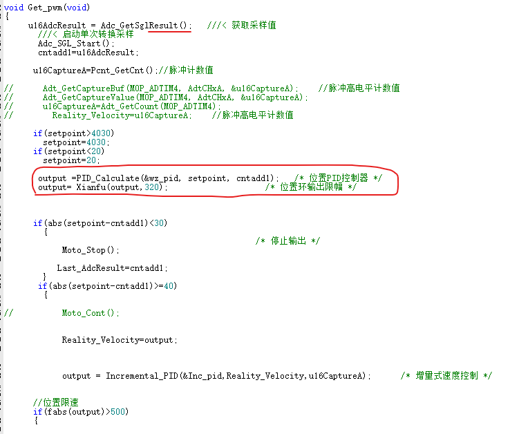
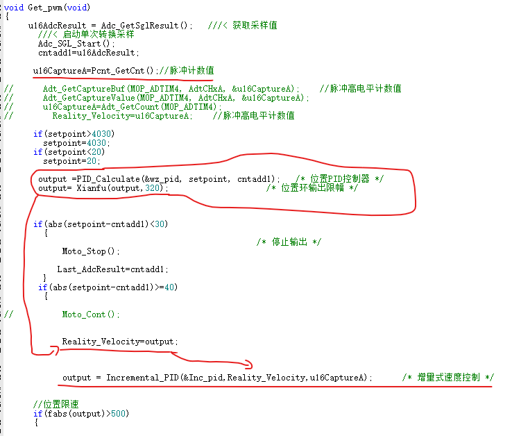
void Get_pwm(void)
{
u16AdcResult = Adc_GetSglResult(); ///< 获取采样值
///< 启动单次转换采样
Adc_SGL_Start();
cntadd1=u16AdcResult;
u16CaptureA=Pcnt_GetCnt();//脉冲计数值
// Adt_GetCaptureBuf(M0P_ADTIM4, AdtCHxA, &u16CaptureA); //脉冲高电平计数值
// Adt_GetCaptureValue(M0P_ADTIM4, AdtCHxA, &u16CaptureA);
// u16CaptureA=Adt_GetCount(M0P_ADTIM4);
// Reality_Velocity=u16CaptureA; //脉冲高电平计数值
if(setpoint>4030)
setpoint=4030;
if(setpoint<20)
setpoint=20;
output =PID_Calculate(&wz_pid, setpoint, cntadd1); /* 位置PID控制器 */
output= Xianfu(output,320); /* 位置环输出限幅 */
if(abs(setpoint-cntadd1)<30)
{
/* 停止输出 */
Moto_Stop();
Last_AdcResult=cntadd1;
}
if(abs(setpoint-cntadd1)>=40)
{
// Moto_Cont();
Reality_Velocity=output;
output = Incremental_PID(&Inc_pid,Reality_Velocity,u16CaptureA); /* 增量式速度控制 */
//位置限速
if(fabs(output)>500)
{
if(abs(Last_AdcResult-setpoint)>=2000 && abs(Last_AdcResult-setpoint)<5000)
{
Target_Velocity=abs(Last_AdcResult-setpoint)/6;
}
if(abs(Last_AdcResult-setpoint)>=1000 && abs(Last_AdcResult-setpoint)<2000)
{
Target_Velocity=abs(Last_AdcResult-setpoint)/4;
}
if(abs(Last_AdcResult-setpoint)>=500 && abs(Last_AdcResult-setpoint)<1000)
{
Target_Velocity=abs(Last_AdcResult-setpoint)/3;
}
if(abs(Last_AdcResult-setpoint)>=100 && abs(Last_AdcResult-setpoint)<500)
{
Target_Velocity=abs(Last_AdcResult-setpoint)/2;
}
if(abs(Last_AdcResult-setpoint)>=0 && abs(Last_AdcResult-setpoint)<100)
{
Target_Velocity=abs(Last_AdcResult-setpoint)/1;
}
if(abs(setpoint-cntadd1)<Target_Velocity) //到临近位置后输出低速
{
output= Xianfu(output,320); //输出低速
}
}
/* 赋值 */
Moto_Star(output);
}
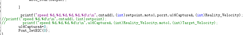
printf("speed:%d,%d,%d,%d,%d,%d\r\n",cntadd1,(int)setpoint,moto1,porzt,u16CaptureA,(int)Reality_Velocity);
//printf("speed:%d,%d\r\n",cntadd1,(int)setpoint);
// printf("speed:%d,%d,%d,%d\r\n",u16CaptureA,(int)Reality_Velocity,moto1,(int)Target_Velocity);
u16CaptureA=0;
Pcnt_SetB2C(0);
}
头文件
#include "adt.h"
#include "ddl.h"

#define Dead_Voltage 0     /* 死区电压 */
#define Set_con      1
extern  en_adt_compare_t         enAdtCompareA;
extern uint16_t u16CaptureA,u16CaptureB;

void Get_pwm(void);
void Set_Pwm(float moto);
void Moto_Stop(void);
void Moto_Star(float out);
int Xianfu(int data,int max);
位置环PID反馈ADC获取
速度环PID反馈为脉冲计数,输入值为位置环的输出。
main.c
/******************************************************************************
* Copyright (C) 2017, Xiaohua Semiconductor Co.,Ltd All rights reserved.
*
* This software is owned and published by:
* Xiaohua Semiconductor Co.,Ltd ("XHSC").
*
* BY DOWNLOADING, INSTALLING OR USING THIS SOFTWARE, YOU AGREE TO BE BOUND
* BY ALL THE TERMS AND CONDITIONS OF THIS AGREEMENT.
*
* This software contains source code for use with XHSC
* components. This software is licensed by XHSC to be adapted only
* for use in systems utilizing XHSC components. XHSC shall not be
* responsible for misuse or illegal use of this software for devices not
* supported herein. XHSC is providing this software "AS IS" and will
* not be responsible for issues arising from incorrect user implementation
* of the software.
*
* Disclaimer:
* XHSC MAKES NO WARRANTY, EXPRESS OR IMPLIED, ARISING BY LAW OR OTHERWISE,
* REGARDING THE SOFTWARE (INCLUDING ANY ACOOMPANYING WRITTEN MATERIALS),
* ITS PERFORMANCE OR SUITABILITY FOR YOUR INTENDED USE, INCLUDING,
* WITHOUT LIMITATION, THE IMPLIED WARRANTY OF MERCHANTABILITY, THE IMPLIED
* WARRANTY OF FITNESS FOR A PARTICULAR PURPOSE OR USE, AND THE IMPLIED
* WARRANTY OF NONINFRINGEMENT.
* XHSC SHALL HAVE NO LIABILITY (WHETHER IN CONTRACT, WARRANTY, TORT,
* NEGLIGENCE OR OTHERWISE) FOR ANY DAMAGES WHATSOEVER (INCLUDING, WITHOUT
* LIMITATION, DAMAGES FOR LOSS OF BUSINESS PROFITS, BUSINESS INTERRUPTION,
* LOSS OF BUSINESS INFORMATION, OR OTHER PECUNIARY LOSS) ARISING FROM USE OR
* INABILITY TO USE THE SOFTWARE, INCLUDING, WITHOUT LIMITATION, ANY DIRECT,
* INDIRECT, INCIDENTAL, SPECIAL OR CONSEQUENTIAL DAMAGES OR LOSS OF DATA,
* SAVINGS OR PROFITS,
* EVEN IF Disclaimer HAS BEEN ADVISED OF THE POSSIBILITY OF SUCH DAMAGES.
* YOU ASSUME ALL RESPONSIBILITIES FOR SELECTION OF THE SOFTWARE TO ACHIEVE YOUR
* INTENDED RESULTS, AND FOR THE INSTALLATION OF, USE OF, AND RESULTS OBTAINED
* FROM, THE SOFTWARE.
*
* This software may be replicated in part or whole for the licensed use,
* with the restriction that this Disclaimer and Copyright notice must be
* included with each copy of this software, whether used in part or whole,
* at all times.
*/
/******************************************************************************/
/** \file main.c
**
** A detailed description is available at
** @link Sample Group Some description @endlink
**
** - 2019-04-22 Husj First Version
**
******************************************************************************/
/******************************************************************************
* Include files
******************************************************************************/
#include "adt.h"
#include "gpio.h"
#include "flash.h"
#include "bt.h"
#include "adc.h"
#include "bgr.h"
#include "pid.h"
#include "stdio.h"
#include "stdlib.h"
#include "math.h"
#include "ddl.h"
#include "uart.h"
#include "vc.h"
#include "pcnt.h"
#include "MOTOR_con.h"
#include "gpio_control.h"
/******************************************************************************
* Local pre-processor symbols/macros ('#define')
******************************************************************************/
/******************************************************************************
* Global variable definitions (declared in header file with 'extern')
******************************************************************************/
/******************************************************************************
* Local type definitions ('typedef')
******************************************************************************/
/******************************************************************************
* Local function prototypes ('static')
******************************************************************************/
/******************************************************************************
* Local variable definitions ('static') *
******************************************************************************/
/*****************************************************************************
* Function implementation - global ('extern') and local ('static')
******************************************************************************/
en_adt_compare_t enAdtCompareA;
en_adt_compare_t enAdtCompareB;
///< 时钟初始化
void App_ClockInit(void)
{
en_flash_waitcycle_t enFlashWait;
stc_sysctrl_pll_cfg_t stcPLLCfg;
DDL_ZERO_STRUCT(stcPLLCfg);
enFlashWait = FlashWaitCycle1; //读等待周期设置为1(当HCLK大于24MHz时必须至少为1)
Flash_WaitCycle(enFlashWait); // Flash 等待1个周期
stcPLLCfg.enInFreq = SysctrlPllInFreq4_6MHz; //RCH 4MHz
stcPLLCfg.enOutFreq = SysctrlPllOutFreq36_48MHz; //PLL 输出48MHz
stcPLLCfg.enPllClkSrc = SysctrlPllRch; //输入时钟源选择RCH
stcPLLCfg.enPllMul = SysctrlPllMul12; //4MHz x 12 = 48MHz
Sysctrl_SetPLLFreq(&stcPLLCfg);
Sysctrl_SetPLLStableTime(SysctrlPllStableCycle16384);
Sysctrl_ClkSourceEnable(SysctrlClkPLL, TRUE);
Sysctrl_SysClkSwitch(SysctrlClkPLL); ///< 时钟切换为PLL锁相环时钟
}
///< AdvTimer端口初始化
void App_AdvTimerPortInit(void)
{
stc_gpio_cfg_t stcTIM5Port;
stc_gpio_cfg_t stcBrakePort;
stc_gpio_cfg_t stcBKTestPort;
stc_gpio_cfg_t stcGpioCfg;
stc_gpio_cfg_t stcUartGpioCfg;
stc_gpio_cfg_t stcTIM4Port;
stc_gpio_cfg_t GpioInitStruct;
DDL_ZERO_STRUCT(GpioInitStruct);
DDL_ZERO_STRUCT(stcGpioCfg);
DDL_ZERO_STRUCT(stcTIM4Port);
DDL_ZERO_STRUCT(stcTIM5Port);
DDL_ZERO_STRUCT(stcBrakePort);
DDL_ZERO_STRUCT(stcBKTestPort);
Sysctrl_SetPeripheralGate(SysctrlPeripheralGpio, TRUE); //端口外设时钟使能
stcTIM5Port.enDir = GpioDirIn;
//PA04设置为TIM50_CHA
Gpio_Init(GpioPortA, GpioPin4, &stcTIM5Port);
Gpio_SetAfMode(GpioPortA,GpioPin4,GpioAf5);
//ADC采样IO口
Gpio_SetAnalogMode(GpioPortA, GpioPin0); //PA00 (AIN0)
//换向端口、控制端口设置
stcGpioCfg.enDir = GpioDirOut;
///< 端口上下拉配置->下拉
// stcGpioCfg.enPu =GpioPuEnable ;
// stcGpioCfg.enPd =GpioPdDisable ;
// Gpio_SetIO(GpioPortD, GpioPin6);
Gpio_Init(GpioPortD, GpioPin6, &stcGpioCfg); //换向端口
stcGpioCfg.enPu =GpioPuEnable ;
Gpio_Init(GpioPortC, GpioPin0, &stcGpioCfg); //控制端口刹车
//串口端口配置
stcUartGpioCfg.enDir = GpioDirOut;
Gpio_Init(GpioPortB,GpioPin6,&stcUartGpioCfg);
Gpio_SetAfMode(GpioPortB,GpioPin6,GpioAf2); //配置PB06 为UART0 TX
stcUartGpioCfg.enDir = GpioDirIn;
Gpio_Init(GpioPortB,GpioPin7,&stcUartGpioCfg);
Gpio_SetAfMode(GpioPortB,GpioPin7,GpioAf2);//配置PB07 为UART0 RX
stcTIM4Port.enDir = GpioDirIn;
//PA08设置为TIM4_CHA
Gpio_Init(GpioPortA, GpioPin8, &stcTIM4Port);
Gpio_SetAfMode(GpioPortA,GpioPin8,GpioAf6);
//PD01设置为TIM4_CHB
// Gpio_Init(GpioPortA, GpioPin7, &stcTIM4Port);
// Gpio_SetAfMode(GpioPortA,GpioPin7,GpioAf7);
GpioInitStruct.enDrv = GpioDrvH;
GpioInitStruct.enDir = GpioDirOut;
Gpio_Init(GpioPortA,GpioPin6,&GpioInitStruct);
Gpio_SetAfMode(GpioPortA,GpioPin6,GpioAf5); //PA06作为比较器VC0_OUT
GpioInitStruct.enDrv = GpioDrvH;
GpioInitStruct.enDir = GpioDirIn;
Gpio_Init(GpioPortB,GpioPin5,&GpioInitStruct);
Gpio_SetAfMode(GpioPortB,GpioPin5,GpioAf6); //PB05作为PCNT_S0
GpioInitStruct.enDrv = GpioDrvH;
GpioInitStruct.enDir = GpioDirIn;
GpioInitStruct.enPu = GpioPuDisable;
GpioInitStruct.enPd = GpioPdEnable;
Gpio_Init(GpioPortD,GpioPin4,&GpioInitStruct);
Gpio_Init(GpioPortD,GpioPin5,&GpioInitStruct);
Gpio_Init(GpioPortD,GpioPin7,&GpioInitStruct);
Gpio_Init(GpioPortB,GpioPin8,&GpioInitStruct);
Gpio_Init(GpioPortC,GpioPin6,&GpioInitStruct);
Gpio_Init(GpioPortB,GpioPin13,&GpioInitStruct);
}
//串口模块配置
void App_UartCfg(void)
{
stc_uart_cfg_t stcCfg;
stc_uart_multimode_t stcMulti;
stc_uart_baud_t stcBaud;
DDL_ZERO_STRUCT(stcCfg);
DDL_ZERO_STRUCT(stcMulti);
DDL_ZERO_STRUCT(stcBaud);
Sysctrl_SetPeripheralGate(SysctrlPeripheralUart0,TRUE);//UART0外设模块时钟使能
stcCfg.enRunMode = UartMskMode3; //模式3
stcCfg.enStopBit = UartMsk1bit; //1位停止位
stcCfg.enMmdorCk = UartMskEven; //偶校验
stcCfg.stcBaud.u32Baud = 9600; //波特率9600
stcCfg.stcBaud.enClkDiv = UartMsk8Or16Div; //通道采样分频配置
stcCfg.stcBaud.u32Pclk = Sysctrl_GetPClkFreq(); //获得外设时钟(PCLK)频率值
Uart_Init(M0P_UART0, &stcCfg); //串口初始化
// Uart_ClrStatus(M0P_UART0,UartRC); //清接收请求
// Uart_ClrStatus(M0P_UART0,UartTC); //清发送请求
// Uart_EnableIrq(M0P_UART0,UartRxIrq); //使能串口接收中断
// Uart_EnableIrq(M0P_UART0,UartTxIrq); //使能串口发送中断
}
//void Tim4_IRQHandler(void)
//{
// //AdvTimer4 捕获中断A
// if(TRUE == Adt_GetIrqFlag(M0P_ADTIM4, AdtCMAIrq))
// {
//// Adt_GetCaptureValue(M0P_ADTIM4, AdtCHxA, &u16Capture); //读取捕获值A
//// Adt_GetCaptureBuf(M0P_ADTIM4, AdtCHxA, &u16CaptureBuf); //读取捕获值A的缓存值
//// Adt_GetCaptureValue(M0P_ADTIM4, AdtCHxA, &u16CaptureA); //脉冲高电平计数值
//// if(1 == Gpio_GetInputIO(GpioPortA, GpioPin8)) //PA08为高电平时
//// {
//// u16CapDuty = (u16CaptureBuf*100) / u16Capture; //计算占空比
//// }
// u16CaptureA++;
// Adt_ClearIrqFlag(M0P_ADTIM4, AdtCMAIrq); //清除捕获中断A的标志
// }
//}
///< AdvTimer端口初始化
//void App_AdtPortInit1(void)
//{
// stc_gpio_cfg_t stcTIM4Port;
//
// DDL_ZERO_STRUCT(stcTIM4Port);
//
// Sysctrl_SetPeripheralGate(SysctrlPeripheralGpio, TRUE); //端口外设时钟使能
//
// stcTIM4Port.enDir = GpioDirIn;
// //PA08设置为TIM4_CHA
// Gpio_Init(GpioPortA, GpioPin8, &stcTIM4Port);
// Gpio_SetAfMode(GpioPortA,GpioPin8,GpioAf6);
// //PA07设置为TIM4_CHB
//// Gpio_Init(GpioPortA, GpioPin7, &stcTIM4Port);
//// Gpio_SetAfMode(GpioPortA,GpioPin7,GpioAf7);
//
//}
///< AdvTimer初始化
void App_AdvTimer4Init(void)
{
uint16_t u16Period;
stc_adt_basecnt_cfg_t stcAdtBaseCntCfg;
stc_adt_CHxX_port_cfg_t stcAdtTIM4ACfg;
stc_adt_CHxX_port_cfg_t stcAdtTIM4BCfg;
DDL_ZERO_STRUCT(stcAdtBaseCntCfg);
DDL_ZERO_STRUCT(stcAdtTIM4ACfg);
DDL_ZERO_STRUCT(stcAdtTIM4BCfg);
Sysctrl_SetPeripheralGate(SysctrlPeripheralAdvTim, TRUE); //ADT外设时钟使能
stcAdtBaseCntCfg.enCntMode = AdtSawtoothMode; //Sawtooth Mode
stcAdtBaseCntCfg.enCntDir = AdtCntUp; // Cnt up
stcAdtBaseCntCfg.enCntClkDiv = AdtClkPClk0Div4; // PCLK0/4
Adt_Init(M0P_ADTIM4, &stcAdtBaseCntCfg); //ADT载波、计数模式、时钟配置
Adt_SetPeriod(M0P_ADTIM4, 0xFFFF); //周期设置
stcAdtTIM4ACfg.enCap = AdtCHxCompareInput; //ChannelA 捕获输入
stcAdtTIM4ACfg.bFltEn = TRUE;
stcAdtTIM4ACfg.enFltClk = AdtFltClkPclk0Div16;
Adt_CHxXPortCfg(M0P_ADTIM4, AdtCHxA, &stcAdtTIM4ACfg); //ChannelA配置捕获输入 & GPIO CHA 输入滤波使能
Adt_EnableValueBuf(M0P_ADTIM4, AdtCHxA, TRUE); //缓存传送功能打开
Adt_CfgHwCaptureA(M0P_ADTIM4, AdtHwTrigCHxARise); //硬件捕获A条件配置:
Adt_CfgHwCaptureA(M0P_ADTIM4, AdtHwTrigCHxAFall); //硬件捕获A条件配置:
Adt_CfgHwClear(M0P_ADTIM4, AdtHwTrigCHxARise); //硬件清零条件:CHA 端口采样到上升沿
Adt_EnableHwClear(M0P_ADTIM4);
// Adt_ClearAllIrqFlag(M0P_ADTIM4);
// Adt_CfgIrq(M0P_ADTIM4, AdtCMAIrq, TRUE); //捕获输入A中断配置
// EnableNvic(ADTIM4_IRQn, IrqLevel3, TRUE); //AdvTimer4中断使能
Adt_StartCount(M0P_ADTIM4); //AdvTimer4 运行
}
///< AdvTimer初始化
void App_AdvTimerInit(uint16_t u16Period, uint16_t u16CHA_PWMDuty, uint16_t u16CHB_PWMDuty)
{
stc_adt_basecnt_cfg_t stcAdtBaseCntCfg;
stc_adt_CHxX_port_cfg_t stcAdtTIM5ACfg;
stc_adt_CHxX_port_cfg_t stcAdtTIM5BCfg;
DDL_ZERO_STRUCT(stcAdtBaseCntCfg);
DDL_ZERO_STRUCT(stcAdtTIM5ACfg);
DDL_ZERO_STRUCT(stcAdtTIM5BCfg);
Sysctrl_SetPeripheralGate(SysctrlPeripheralAdvTim, TRUE);//ADT外设时钟使能
stcAdtBaseCntCfg.enCntMode = AdtSawtoothMode;
stcAdtBaseCntCfg.enCntDir = AdtCntUp;
stcAdtBaseCntCfg.enCntClkDiv = AdtClkPClk0;
Adt_Init(M0P_ADTIM5, &stcAdtBaseCntCfg); //ADT载波、计数模式、时钟配置
Adt_SetPeriod(M0P_ADTIM5, u16Period); //周期值
enAdtCompareA = AdtCompareA;
Adt_SetCompareValue(M0P_ADTIM5, enAdtCompareA, u16CHA_PWMDuty); //通用比较基准值寄存器A设置
enAdtCompareB = AdtCompareB;
Adt_SetCompareValue(M0P_ADTIM5, enAdtCompareB, u16CHB_PWMDuty); //通用比较基准值寄存器B设置
stcAdtTIM5ACfg.enCap = AdtCHxCompareOutput; //比较输出
stcAdtTIM5ACfg.bOutEn = TRUE; //CHA输出使能
stcAdtTIM5ACfg.enPerc = AdtCHxPeriodHigh;//AdtCHxPeriodLow; //计数值与周期匹配时CHA电平保持不变
stcAdtTIM5ACfg.enCmpc = AdtCHxCompareLow;//AdtCHxCompareHigh; //计数值与比较值A匹配时,CHA电平翻转
// stcAdtTIM5ACfg.enPerc = AdtCHxPeriodLow; //计数值与周期匹配时CHA电平保持不变
// stcAdtTIM5ACfg.enCmpc = AdtCHxCompareHigh; //计数值与比较值A匹配时,CHA电平翻转
stcAdtTIM5ACfg.enStaStp = AdtCHxStateSelSS; //CHA起始结束电平由STACA与STPCA控制
stcAdtTIM5ACfg.enStaOut = AdtCHxPortOutLow; //CHA起始电平为低AdtCHxPortOutHigh AdtCHxPortOutLow
stcAdtTIM5ACfg.enStpOut = AdtCHxPortOutLow; //CHA结束电平为低
stcAdtTIM5ACfg.enDisSel = AdtCHxDisSel3; //选择强制输出无效条件3(刹车条件3)
stcAdtTIM5ACfg.enDisVal =AdtTIMxDisValLow; //AdtTIMxDisValHigh , AdtTIMxDisValLow; //刹车时CHA端口输出低电平
Adt_CHxXPortCfg(M0P_ADTIM5, AdtCHxA, &stcAdtTIM5ACfg); //CHA端口配置
stcAdtTIM5BCfg.enCap = AdtCHxCompareOutput;
stcAdtTIM5BCfg.bOutEn = TRUE;
stcAdtTIM5BCfg.enPerc = AdtCHxPeriodInv;
stcAdtTIM5BCfg.enCmpc = AdtCHxCompareInv;
stcAdtTIM5BCfg.enStaStp = AdtCHxStateSelSS;
stcAdtTIM5BCfg.enStaOut = AdtCHxPortOutLow;
stcAdtTIM5BCfg.enStpOut = AdtCHxPortOutLow;
Adt_CHxXPortCfg(M0P_ADTIM5, AdtCHxB, &stcAdtTIM5BCfg); //端口CHB配置
Adt_StartCount(M0P_ADTIM5); //开启TIM5,输出pwm
}
//Timer0配置初始化
void App_Timer0Cfg(uint16_t u16Period)
{
uint16_t u16ArrValue;
uint16_t u16CntValue;
stc_bt_mode0_cfg_t stcBtBaseCfg;
DDL_ZERO_STRUCT(stcBtBaseCfg);
Sysctrl_SetPeripheralGate(SysctrlPeripheralBaseTim, TRUE); //Base Timer外设时钟使能
stcBtBaseCfg.enWorkMode = BtWorkMode0; //定时器模式
stcBtBaseCfg.enCT = BtTimer; //定时器功能,计数时钟为内部PCLK
stcBtBaseCfg.enPRS = BtPCLKDiv16; //PCLK/16
stcBtBaseCfg.enCntMode = Bt16bitArrMode; //自动重载16位计数器/定时器
stcBtBaseCfg.bEnTog = FALSE;
stcBtBaseCfg.bEnGate = FALSE;
stcBtBaseCfg.enGateP = BtGatePositive;
Bt_Mode0_Init(TIM0, &stcBtBaseCfg); //TIM0 的模式0功能初始化
u16ArrValue = u16Period;
Bt_M0_ARRSet(TIM0, u16ArrValue); //设置重载值(ARR = 周期)
u16CntValue = u16Period;
Bt_M0_Cnt16Set(TIM0, u16CntValue); //设置计数初值
Bt_ClearIntFlag(TIM0,BtUevIrq); //清中断标志
Bt_Mode0_EnableIrq(TIM0); //使能TIM0中断(模式0时只有一个中断)
EnableNvic(TIM0_IRQn, IrqLevel0, TRUE); //TIM0中断使能
Bt_M0_Run(TIM0); //TIM0 运行。
}
///< ADC模块 初始化
void App_AdcInit(void)
{
stc_adc_cfg_t stcAdcCfg;
DDL_ZERO_STRUCT(stcAdcCfg);
///< 开启ADC/BGR 外设时钟
Sysctrl_SetPeripheralGate(SysctrlPeripheralAdcBgr, TRUE);
Bgr_BgrEnable(); ///< 开启BGR
///< ADC 初始化配置
stcAdcCfg.enAdcMode = AdcSglMode; ///<采样模式-单次
stcAdcCfg.enAdcClkDiv = AdcMskClkDiv1; ///<采样分频-1
stcAdcCfg.enAdcSampCycleSel = AdcMskSampCycle4Clk; ///<采样周期数-4
stcAdcCfg.enAdcRefVolSel = AdcMskRefVolSelAVDD; ///<参考电压选择-电源电压AVDD
stcAdcCfg.enAdcOpBuf = AdcMskBufDisable; ///<OP BUF配置-关
stcAdcCfg.enInRef = AdcMskInRefDisable; ///<内部参考电压关
stcAdcCfg.enAdcAlign = AdcAlignRight; ///<转换结果对齐方式-右
Adc_Init(&stcAdcCfg);
///< ADC 采样通道配置
Adc_CfgSglChannel(AdcExInputCH0);
///< 启动单次转换采样
Adc_SGL_Start();
}
static void App_VC0Init(void)
{
stc_vc_channel_cfg_t VcInitStruct;
DDL_ZERO_STRUCT(VcInitStruct);
stc_vc_dac_cfg_t VcInitdac;
DDL_ZERO_STRUCT(VcInitdac);
Sysctrl_SetPeripheralGate(SysctrlPeripheralVcLvd, TRUE); //开LVD时钟
Sysctrl_SetPeripheralGate(SysctrlPeripheralAdcBgr, TRUE);//开adc时钟
Bgr_BgrEnable(); //BGR必须使能
VcInitStruct.enVcChannel = VcChannel0;
VcInitStruct.enVcCmpDly = VcDelay10mv; //VC0迟滞电压约为10mV
VcInitStruct.enVcBiasCurrent = VcBias10ua; //VC0功耗为10uA
VcInitStruct.enVcFilterTime = VcFilter28us; //VC输出滤波时间约为28us
VcInitStruct.enVcInPin_P = VcInPCh5; //VC0_CH的P端连接PA01
VcInitStruct.enVcInPin_N = ResDivOut;//AiBg1p2; //VC0_CH的N端连接内核1.2V
VcInitStruct.enVcOutCfg = VcOutDisable; //不输出给配置寄存器所定义的外设
VcInitStruct.bFlten = TRUE; //是能滤波
Vc_Init(&VcInitStruct);
VcInitdac.bDivEn=TRUE;
VcInitdac.u8DivVal=5;
VcInitdac.enDivVref=VcDivVrefAvcc;
Vc_DacInit(&VcInitdac);
Vc_Cmd(VcChannel0, TRUE);
///< VC0 中断配置
// Vc_CfgItType(VcChannel0, VcIrqFall); //配置VC0为上升沿中断
// Vc_ClearItStatus(Vc0_Intf);
// Vc_ItCfg(VcChannel0, TRUE);
// EnableNvic(VC0_IRQn, IrqLevel3, TRUE);
}
/**
******************************************************************************
** \brief 配置PCNT脉冲计数
**
** \return 无
******************************************************************************/
static void App_PcntInit(void)
{
stc_pcnt_initstruct_t PcntInitStruct;
DDL_ZERO_STRUCT(PcntInitStruct);
Sysctrl_SetPeripheralGate(SysctrlPeripheralPcnt, TRUE);
PcntInitStruct.Pcnt_S0Sel = PcntS0PNoinvert; //S0输入极性不取反
PcntInitStruct.Pcnt_Clk = PcntCLKPclk; //采样时钟
PcntInitStruct.Pcnt_Mode = PcntSingleMode; //单通道脉冲计数模式
PcntInitStruct.Pcnt_FltEn = TRUE; //滤波使能
PcntInitStruct.Pcnt_DebTop = 5; //滤波计数器阈值
PcntInitStruct.Pcnt_ClkDiv = 1; //滤波时钟分频系数
PcntInitStruct.Pcnt_TocrEn = FALSE; //超时控制使能
PcntInitStruct.Pcnt_Dir = PcntDirUp; //向上计数
Pcnt_Init(&PcntInitStruct);
Pcnt_SetB2T(65535);
Pcnt_ClrItStatus(PcntOV);
Pcnt_ItCfg(PcntOV, TRUE);
EnableNvic(PCNT_IRQn, IrqLevel3, TRUE);
Pcnt_Cmd(TRUE); //使能PCNT
}
/*******************************************************************************
* TIM0中断服务函数
******************************************************************************/
void Tim0_IRQHandler(void)
{
//Timer0 模式0 溢出中断
if(TRUE == Bt_GetIntFlag(TIM0, BtUevIrq))
{
// Get_pwm();
Handle_Buttons();
Bt_ClearIntFlag(TIM0,BtUevIrq); //中断标志清零
}
}
/**
******************************************************************************
** \brief Main function of project
**
** \return uint32_t return value, if needed
**
** This sample
**
******************************************************************************/
int32_t main(void)
{
stc_adt_disable_3_cfg_t stcAdtDisable3;
DDL_ZERO_STRUCT(stcAdtDisable3);
App_ClockInit(); //时钟初始化
App_AdvTimerPortInit(); //端口初始化
App_AdvTimerInit(2000, 1000,1000); //AdvTimer5初始化pwm//配置为三角波模式: 初始化周期4000, CHA占空比设置2000
// App_AdvTimer4Init(); //TIM4
App_Timer0Cfg(30000); //10ms一次定时中断定时
App_AdcInit(); //开启ADC
///< VC0 比较器初始化
App_VC0Init();
App_PcntInit(); //脉冲计数初始化
App_UartCfg(); //串口
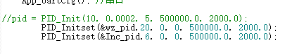
//pid = PID_Init(10, 0.0002, 5, 500000.0, 2000.0);
PID_Initset(&wz_pid,20, 0, 0, 500000.0, 2000.0);
PID_Initset(&Inc_pid,6, 0, 0, 500000.0, 2000.0);
u16CaptureA=0;
while(1)
{
// Adt_SetCompareValue(M0P_ADTIM5, enAdtCompareA, 1000);
}
}
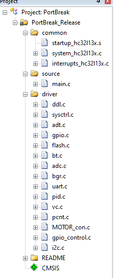
需要的库
PID值调试使用VOFA程序,单片机串口输出值,VOFA程序查看波形慢慢调试PID值
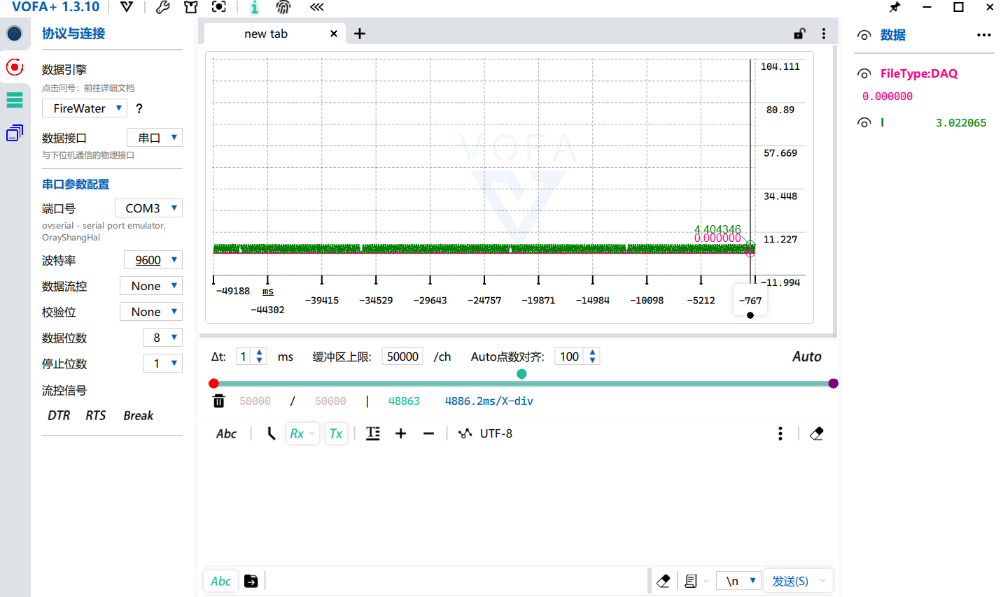
 最后得到PID值
位置环和速度环的PID值


 705
705

 被折叠的 条评论
为什么被折叠?
被折叠的 条评论
为什么被折叠?
 到【灌水乐园】发言


