


一、介绍
DS1302是一款实时时钟(RTC)芯片,它能够为微控制器提供年、月、日、星期、时、分、秒的时间信息,并且可以通过简单的串行接口进行通信。DS1302 具有低功耗、备用电池接口和 RAM 存储等功能,广泛应用于需要时间记录的电子设备中。
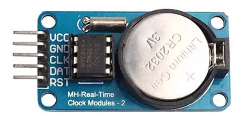
以上是我们要使用的模块,芯片的详细介绍看一看之前在蓝桥杯里面的介绍。
二、程序
采用STM32F407来驱动,下列是引脚接口:
|
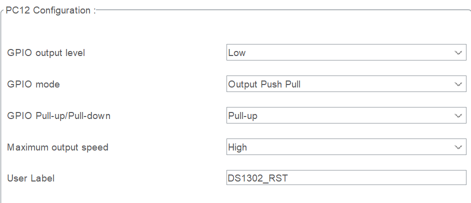
DS1302_RST |
PC12 |
|
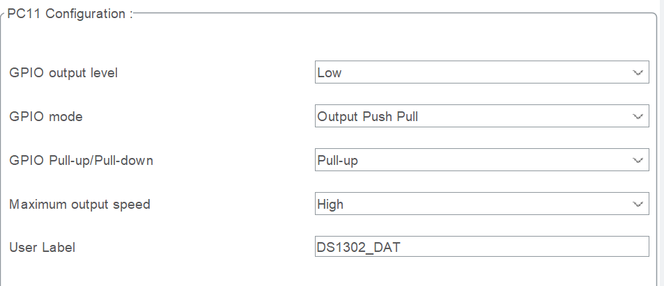
DS1302_DAT |
PC11 |
|
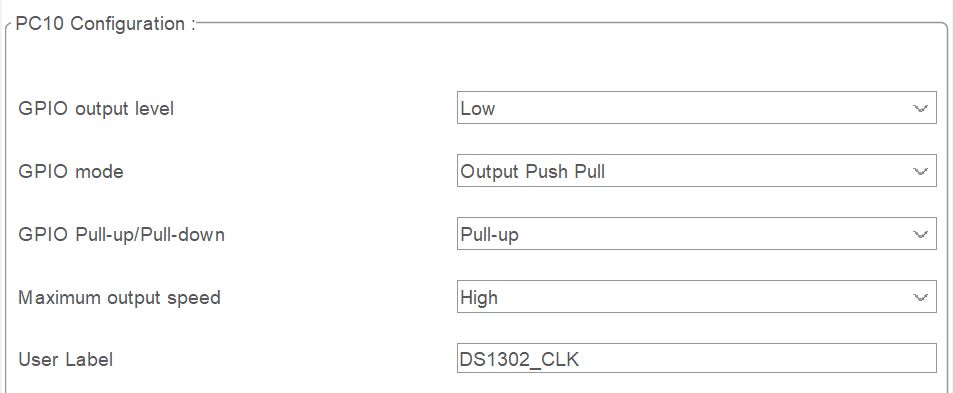
DS1302_CLK |
PC10 |
1、CubeMX配置
将三个GPIO都初始化为推挽上拉输出,输出速度不必太高。
2、编写一个微秒延时函数(这个并不准确,如果需要更准确的延时,建议采用定时器)
// 添加微秒级延时函数
void Delay_us(uint32_t us)
{
    uint32_t delay = (HAL_RCC_GetHCLKFreq() / 4000000 * us);
    while (delay--)
    {
        __NOP();
    }
}
3、DS1302.c文件
uint8_t DS1302_Time[3] = {23, 59, 50}; //初始时间 23:59:50
uint8_t RTC_Write_Addr[3] = {0x84, 0x82, 0x80};
uint8_t RTC_Read_Addr[3] = {0x85, 0x83, 0x81};
void DS1302_DataPin_Input(void)
{
    GPIO_InitTypeDef GPIO_InitStruct;
    GPIO_InitStruct.Pin = DS1302_DAT_Pin;
    GPIO_InitStruct.Mode = GPIO_MODE_INPUT;
    GPIO_InitStruct.Pull = GPIO_NOPULL;
    HAL_GPIO_Init(DS1302_DAT_GPIO_Port, &GPIO_InitStruct);
}

void DS1302_DataPin_Output(void)
{
    GPIO_InitTypeDef GPIO_InitStruct;
    GPIO_InitStruct.Pin = DS1302_DAT_Pin;
    GPIO_InitStruct.Mode = GPIO_MODE_OUTPUT_PP;
    GPIO_InitStruct.Pull = GPIO_PULLUP;
    GPIO_InitStruct.Speed = GPIO_SPEED_FREQ_HIGH;
    HAL_GPIO_Init(DS1302_DAT_GPIO_Port, &GPIO_InitStruct);
}
/*RST*/
#define CE_L HAL_GPIO_WritePin(DS1302_RST_GPIO_Port, DS1302_RST_Pin, GPIO_PIN_RESET)
#define CE_H HAL_GPIO_WritePin(DS1302_RST_GPIO_Port, DS1302_RST_Pin, GPIO_PIN_SET)
/*SCLK*/
#define SCLK_L HAL_GPIO_WritePin(DS1302_CLK_GPIO_Port, DS1302_CLK_Pin, GPIO_PIN_RESET)
#define SCLK_H HAL_GPIO_WritePin(DS1302_CLK_GPIO_Port, DS1302_CLK_Pin, GPIO_PIN_SET)
/*IO*/
#define IO_L HAL_GPIO_WritePin(DS1302_DAT_GPIO_Port, DS1302_DAT_Pin, GPIO_PIN_RESET)
#define IO_H HAL_GPIO_WritePin(DS1302_DAT_GPIO_Port, DS1302_DAT_Pin, GPIO_PIN_SET)
void Write_DS1302(uint8_t dat)
{
    DS1302_DataPin_Output();
    for(uint8_t i=0; i<8; i++)
    {
		SCLK_L;
        if(dat & 0x01) IO_H;
        else IO_L;
		Delay_us(2);
        SCLK_H;
        Delay_us(2);

        dat >>= 1;
    }
}

void Write_DS1302_Byte(uint8_t addr, uint8_t dat)
{
    CE_L;
    SCLK_L; Delay_us(5);
    CE_H;   Delay_us(5);
    Write_DS1302(addr);
    Write_DS1302(dat);
    CE_L;
    SCLK_L;
}

uint8_t Read_DS1302_Byte(uint8_t addr)
{
    uint8_t dat = 0;
    CE_L;
    SCLK_L; Delay_us(5);
    CE_H;  	Delay_us(5);
    Write_DS1302(addr);
    DS1302_DataPin_Input();
    for(uint8_t i=0; i<8; i++)
    {
		SCLK_L;
		Delay_us(2);
		dat >>= 1;
		if(HAL_GPIO_ReadPin(DS1302_DAT_GPIO_Port, DS1302_DAT_Pin) == GPIO_PIN_SET)
            dat |= 0x80;
        SCLK_H;
		Delay_us(2);


    }
	CE_L;	Delay_us(2);
	SCLK_L;	Delay_us(2);

    return dat;
}

void DS1302_SetTime(void)
{
    uint8_t i=0;
    Write_DS1302_Byte(0x8E, 0x00); // Disable write protection
    for(i=0; i<3; i++)
    {
        Write_DS1302_Byte(RTC_Write_Addr[i], (DS1302_Time[i] / 10 * 16 + DS1302_Time[i] % 10));
    }
    Write_DS1302_Byte(0x8E, 0x80); // Enable write protection
}

void DS1302_GetTime(void)
{
    uint8_t i=0, temp=0;
    for(i=0; i<3; i++)
    {
        temp = Read_DS1302_Byte(RTC_Read_Addr[i]);
        DS1302_Time[i] = (temp / 16 * 10 + temp % 16);
    }
}
4、DS1302.h文件
#ifndef __DS1302_H
#define __DS1302_H

#include "main.h"
#include "gpio.h"
#include "oled.h"

extern uint8_t DS1302_Time[3];

void DS1302_SetTime(void);
void DS1302_GetTime(void);

#endif


 887
887

 被折叠的 条评论
为什么被折叠?
被折叠的 条评论
为什么被折叠?
 到【灌水乐园】发言


