


简介
本文详细介绍了如何在S32SD项目中通过Processor Expert自动生成代码的方式使用MPC5744P进行CAN通信。从新建项目、配置ProcessorExpert、自动生成代码到编译下载,一步步引导读者实现CAN报文的发送和接收功能。
一、创建工程
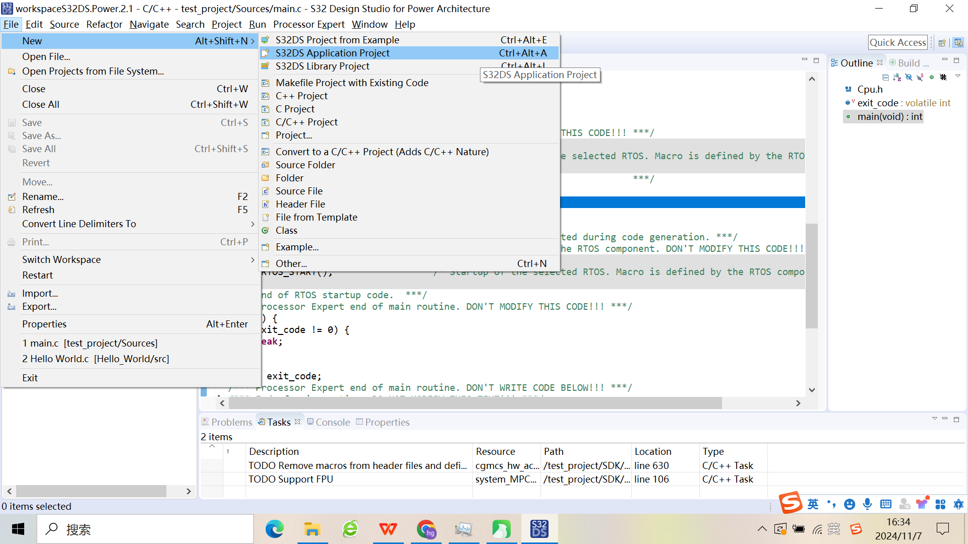
- 点击File->New->S32DS Application Project创建空白工程**。**
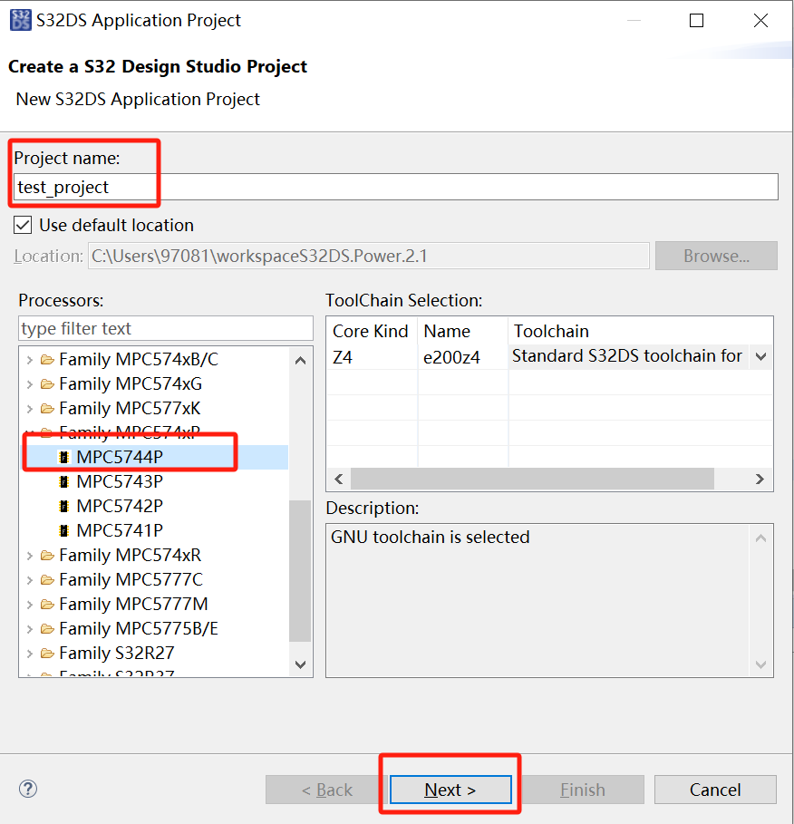
- 接着弹出如下工程配置界面。填写Project name工程名,Processors选择MPC5744P,点击Next。
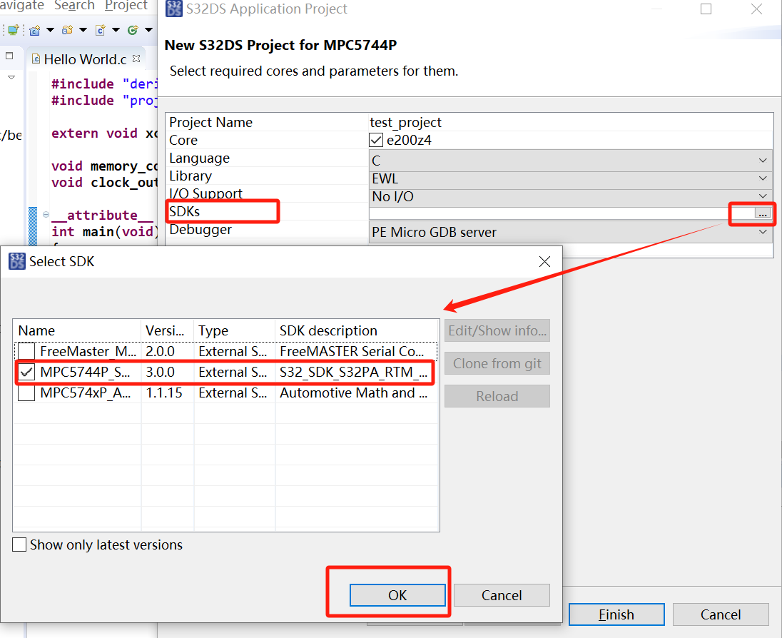
- 选择SDKs的版本,点击OK,如下图。
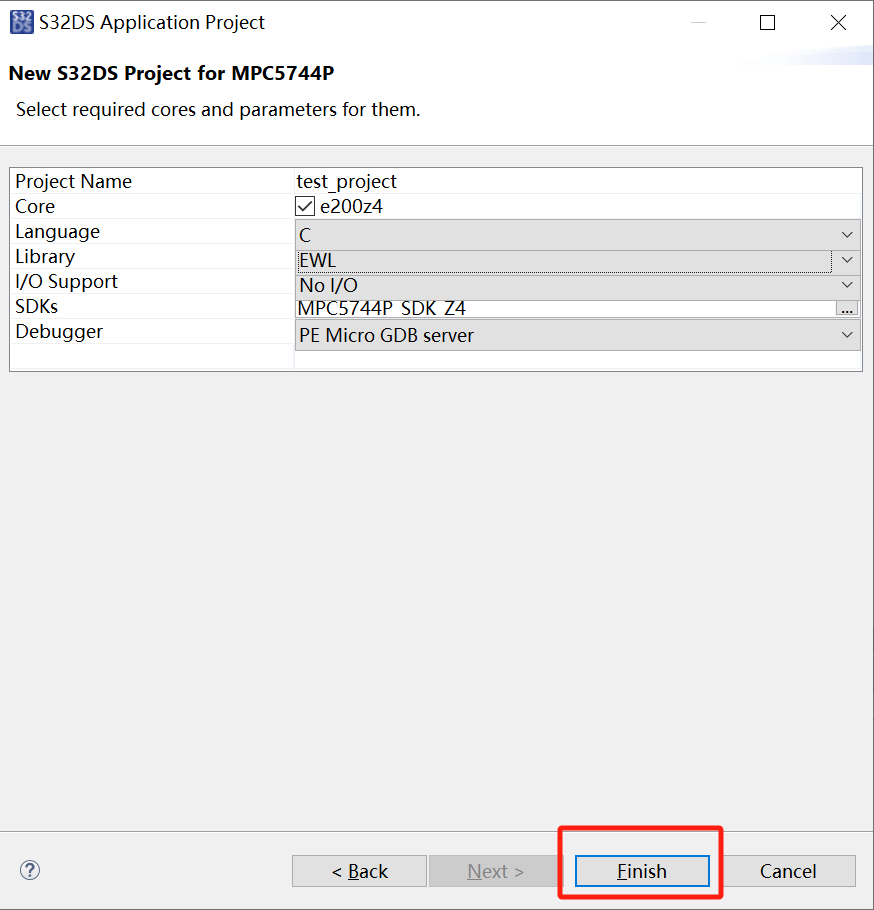
- 点击Finish。
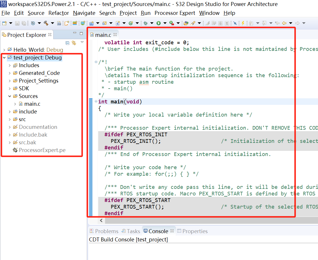
- 新建工程成功,如下图。
二、Processor Expert可视化界面配置
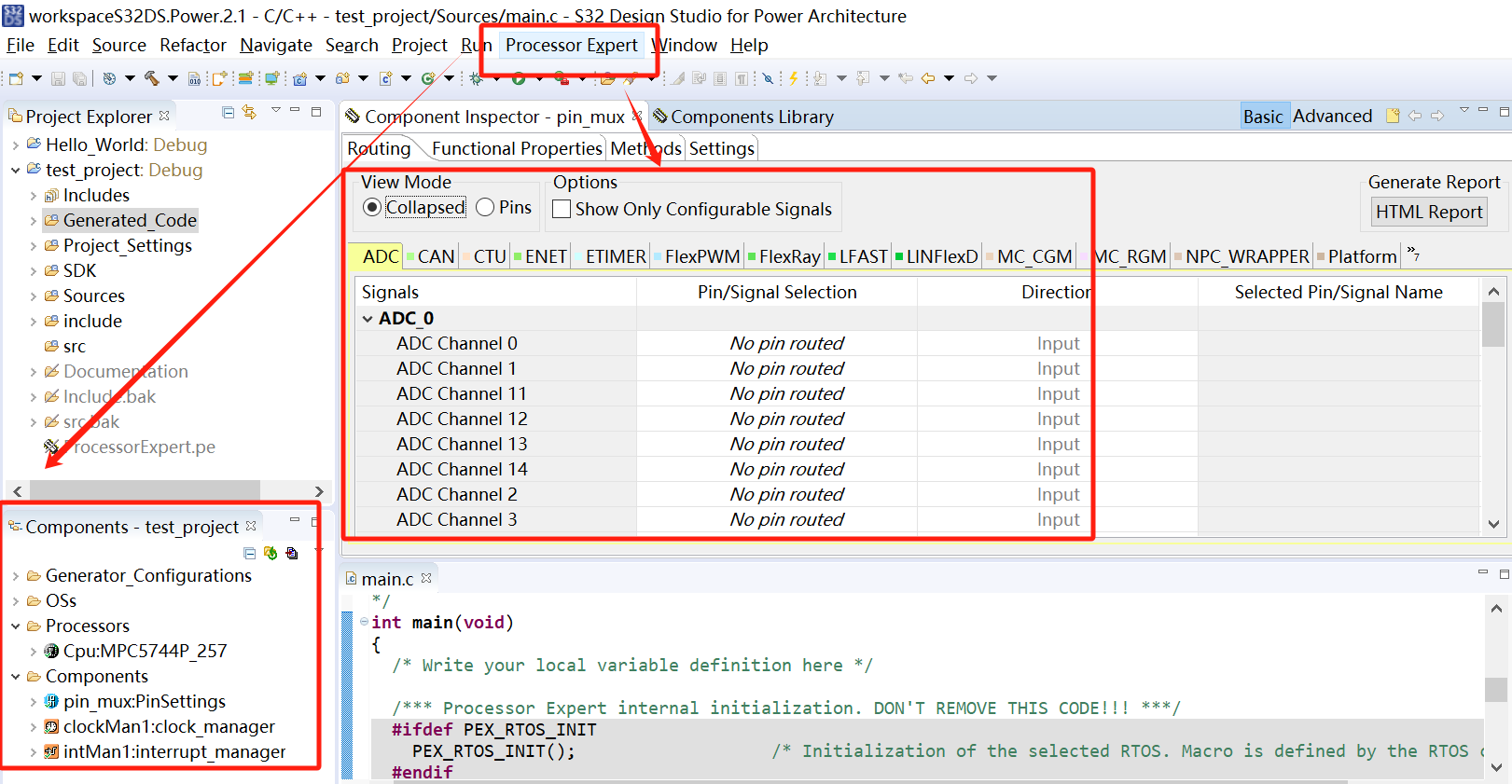
- 我们可以通过图形界面配置进行驱动代码的生成。点击主菜单区域的Processor Expert按钮,选择Show Views,弹出图形化界面,此时,我们可以通过图形界面对外设(GPIO、ADC、CAN等)进行配置。
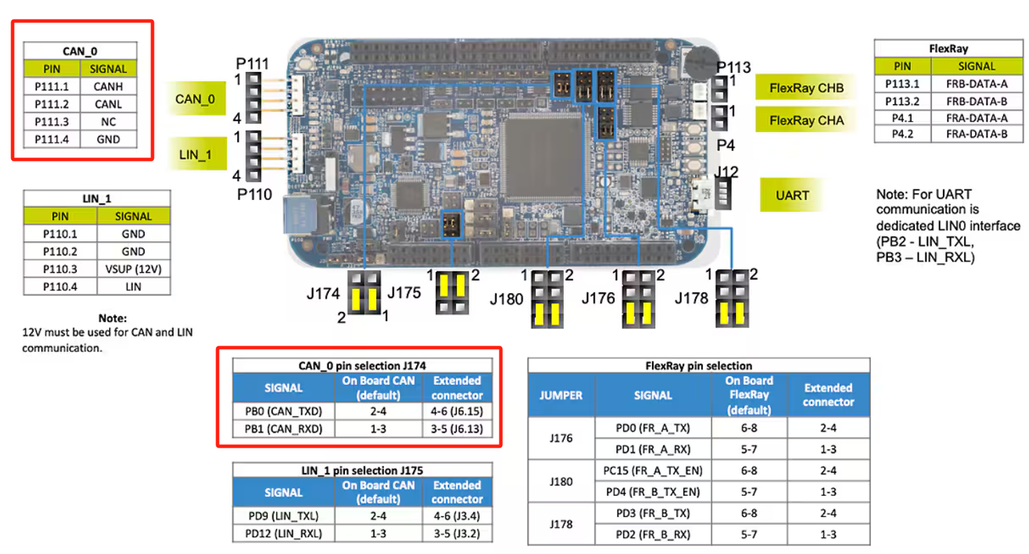
- 参考官方CAN通信接口,进行后续的配置。
注意:这里将开发板的J174端子进行如下图的连接,2接4,1接3。我们将CAN接口接出来跟外部的CAN连接,方便测试。然后外部的CAN盒设备与P111端子的CANH、CANL相连接。另外,CAN通信需要12V外部供电。
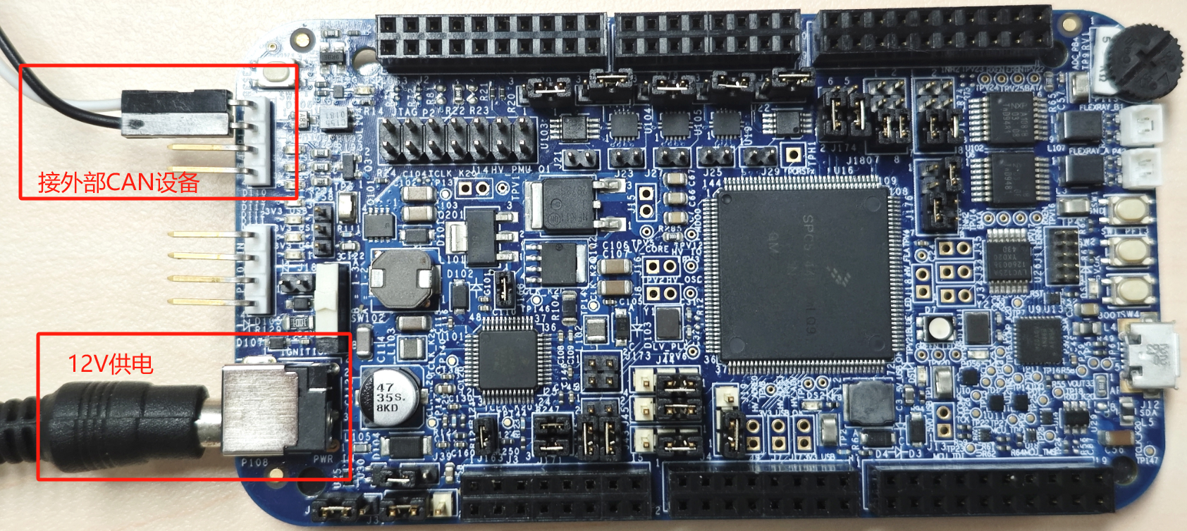
- 开发板的接线图如下图所示。
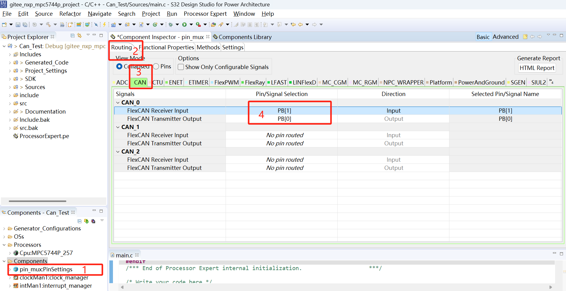
- 双击pin_mux,选中Component Inspector界面,然后在Routing界面选中Collapse,点击CAN,打开CAN引脚的配置界面。按照下图所示,我们来设置CAN的引脚。
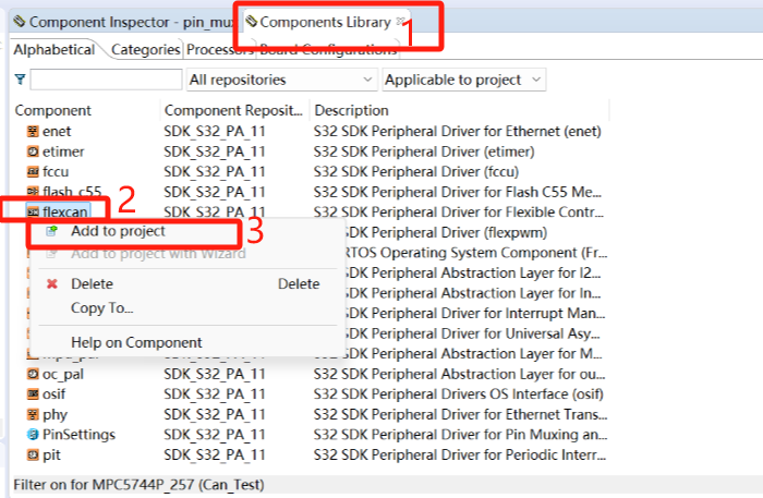
- 点击Components Library,选择flexcan,右键选择Add to project。将CAN驱动添加进项目中去。
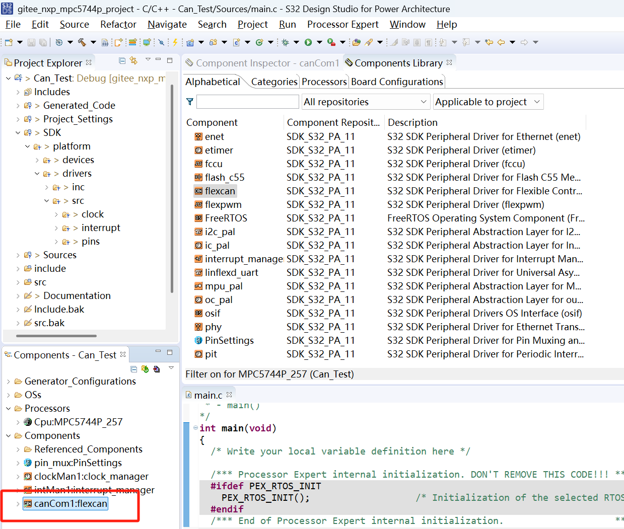
- 添加成功后,如下图。
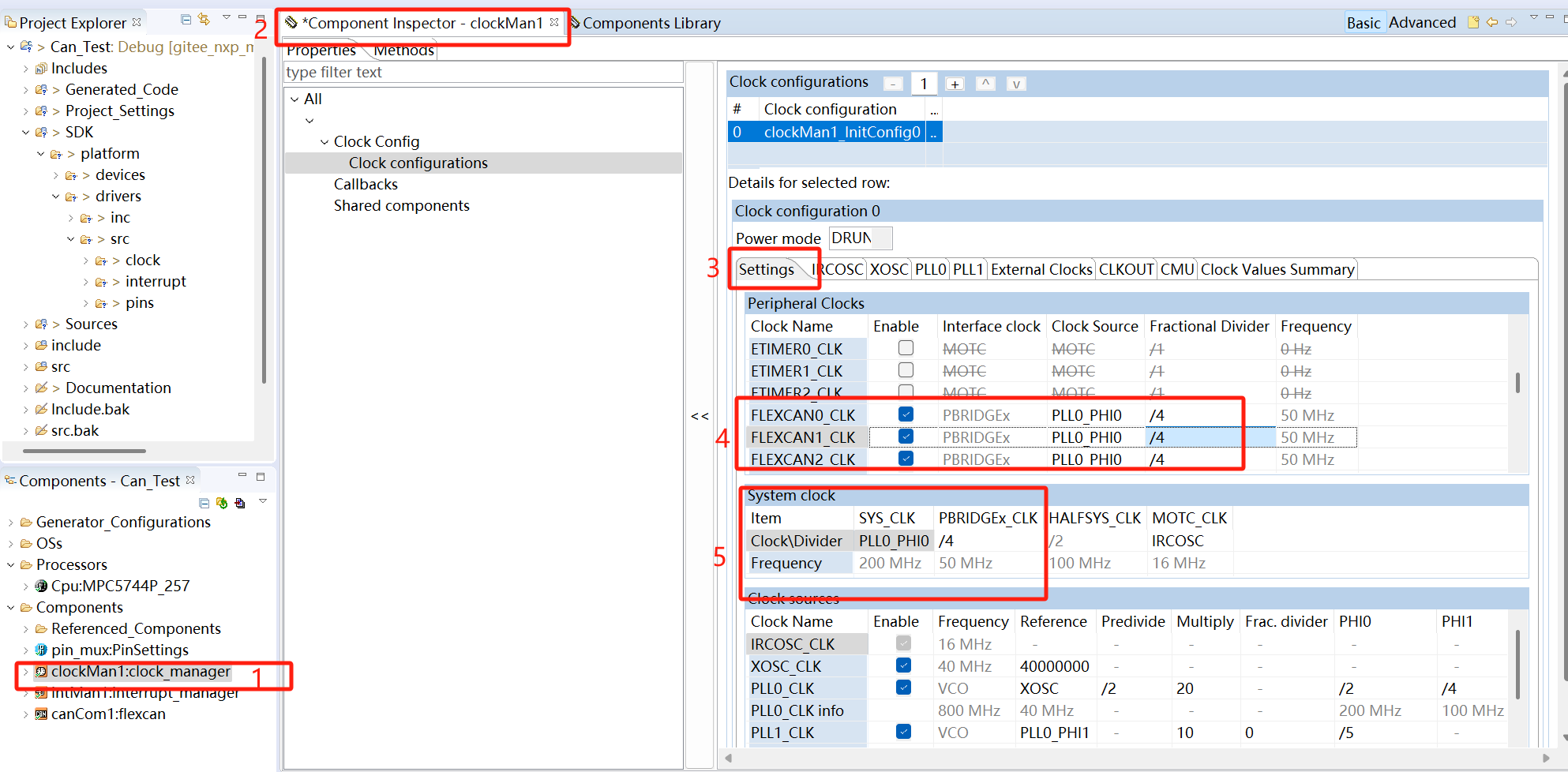
- 配置时钟,选中clockMain1,在Components Inspector -> clockMain1 -> Clock configurations -> Settings中,将CAN接口时钟和外设桥时钟设为50MHz。
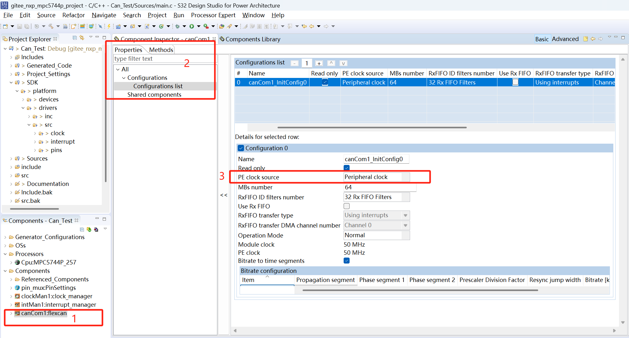
- 配置CAN,选中canCom1,在Components Inspector -> canCom1 -> Configuration list中,我们将PE clock source选择为Peripheral clock。其他的一些属性可以根据需求设置。此时采用默认配置,并且默认的CAN波特率为500Kbps。
三、代码生成
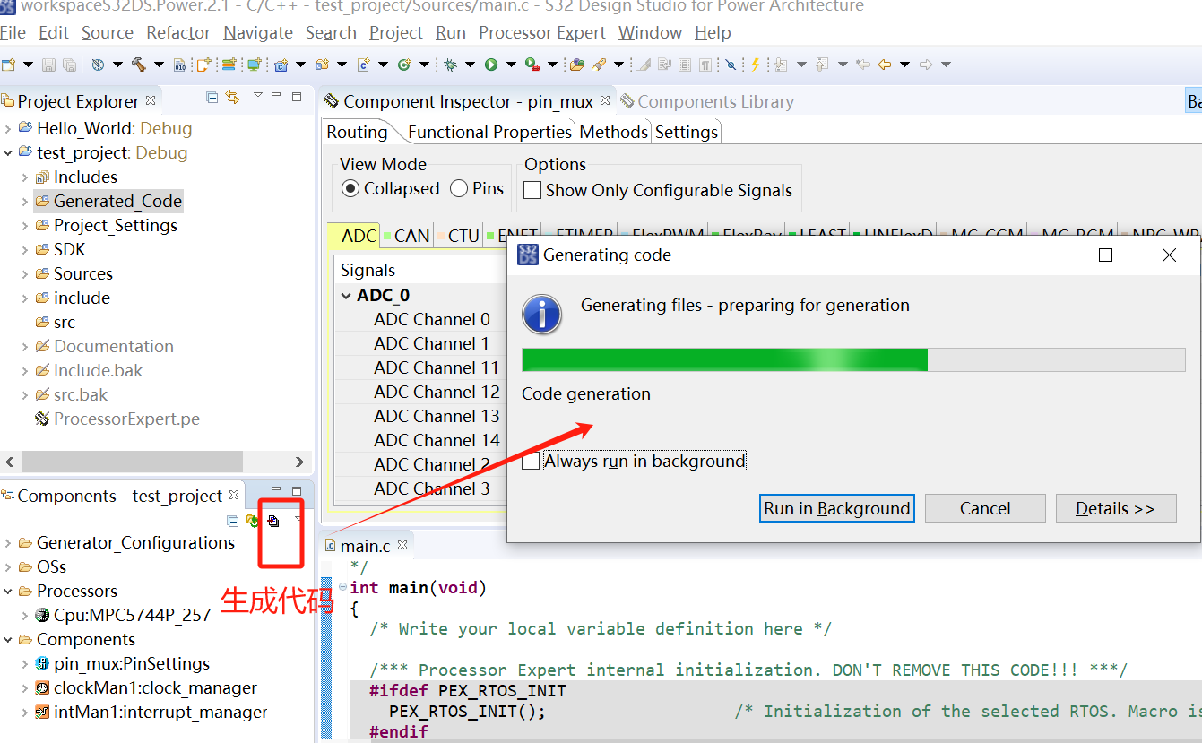
- 配置完成并保存后,开始生成对应配置的驱动代码。点击Components区的生成代码按钮,开始生成代码。
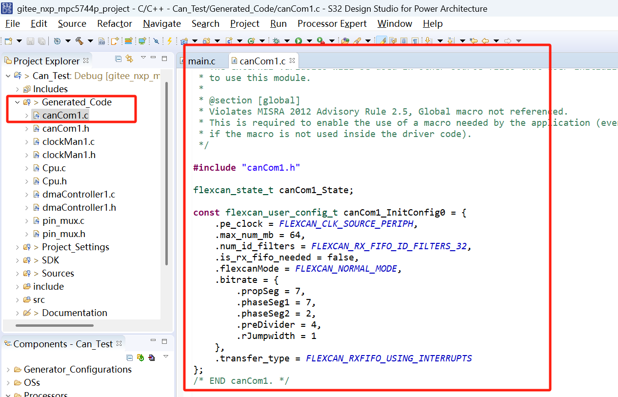
- 代码生成成功,如下图。刚才配置了1个CAN,这里就有了对1个CAN接口配置数组。
四、代码调用
- 驱动代码生成后,我们需要在main.c中调用生成的驱动代码,才能够实现功能。具体的sdk的can驱动api接口在如下图所示文件夹中,我们可以根据该api接口进行功能实现。

- main.c代码示例:
/*
 * Copyright (c) 2013 - 2015, Freescale Semiconductor, Inc.
 * Copyright 2016-2017 NXP
 * All rights reserved.
 *
 * THIS SOFTWARE IS PROVIDED BY NXP "AS IS" AND ANY EXPRESSED OR
 * IMPLIED WARRANTIES, INCLUDING, BUT NOT LIMITED TO, THE IMPLIED WARRANTIES
 * OF MERCHANTABILITY AND FITNESS FOR A PARTICULAR PURPOSE ARE DISCLAIMED.
 * IN NO EVENT SHALL NXP OR ITS CONTRIBUTORS BE LIABLE FOR ANY DIRECT,
 * INDIRECT, INCIDENTAL, SPECIAL, EXEMPLARY, OR CONSEQUENTIAL DAMAGES
 * (INCLUDING, BUT NOT LIMITED TO, PROCUREMENT OF SUBSTITUTE GOODS OR
 * SERVICES; LOSS OF USE, DATA, OR PROFITS; OR BUSINESS INTERRUPTION)
 * HOWEVER CAUSED AND ON ANY THEORY OF LIABILITY, WHETHER IN CONTRACT,
 * STRICT LIABILITY, OR TORT (INCLUDING NEGLIGENCE OR OTHERWISE) ARISING
 * IN ANY WAY OUT OF THE USE OF THIS SOFTWARE, EVEN IF ADVISED OF
 * THE POSSIBILITY OF SUCH DAMAGE.
 */
/* ###################################################################
 **     Filename    : main.c
 **     Processor   : MPC574xP
 **     Abstract    :
 **         Main module.
 **         This module contains user's application code.
 **     Settings    :
 **     Contents    :
 **         No public methods
 **
 ** ###################################################################*/
/*!
 ** @file main.c
 ** @version 01.00
 ** @brief
 **         Main module.
 **         This module contains user's application code.
 */
/*!
 **  @addtogroup main_module main module documentation
 **  @{
 */
/* MODULE main */

/* Including necessary module. Cpu.h contains other modules needed for compiling.*/
#include "Cpu.h"

volatile int exit_code = 0;
/* User includes (#include below this line is not maintained by Processor Expert) */
#define ReceiveCANID 0x00000215
#define SendCANID 0x00000215
uint8_t data[8];

void FlexCAN_Initial(void) {
	uint32_t mailbox = 5;

	FLEXCAN_DRV_Init(INST_CANCOM1, &canCom1_State, &canCom1_InitConfig0); //default is 500K init can0

	flexcan_data_info_t dataInfo =

	{ .data_length = 8U, .msg_id_type = FLEXCAN_MSG_ID_STD };

	/* Configure RX message buffer with index RX_MSG_ID and RX_MAILBOX */
	FLEXCAN_DRV_ConfigRxMb(INST_CANCOM1, mailbox, &dataInfo, ReceiveCANID);
}

void FlexCAN_SendData(uint8_t * data, uint32_t len) {
	uint32_t mailbox = 0;
	/* Set information about the data to be sent
	 *  - 1 byte in length
	 *  - Standard message ID
	 *  - Bit rate switch enabled to use a different <u>bitrate</u> for the data
	 segment
	 *  - Flexible data rate enabled
	 *  - Use zeros for FD padding
	 */
	flexcan_data_info_t dataInfo =

	{ .data_length = len, .msg_id_type = FLEXCAN_MSG_ID_STD };

	/* Configure TX message buffer with index TX_MSG_ID and TX_MAILBOX*/
	FLEXCAN_DRV_ConfigTxMb(INST_CANCOM1, mailbox, &dataInfo, SendCANID);

	/* Execute send non-blocking */
	FLEXCAN_DRV_Send(INST_CANCOM1, mailbox, &dataInfo, SendCANID, data);
}

uint8_t FlexCAN_ReceiveData(void) {
	/* Define receive buffer */
	flexcan_msgbuff_t recvBuff;
	uint32_t mailbox = 5;        //初始化时已设置接收邮箱为5
	uint32_t status = 0;

	status = ((CAN_0->IFLAG1) >> mailbox) & 0x01;
	//MailBox is receive buffer
	if (status != 1) {
		return 0;
	}

	/* Start receiving data in RX_MAILBOX. */
	FLEXCAN_DRV_Receive(INST_CANCOM1, mailbox, &recvBuff);

	/* Wait until the previous FlexCAN receive is completed */
	if (FLEXCAN_DRV_GetTransferStatus(INST_CANCOM1, mailbox)
			== STATUS_SUCCESS) {
		/* Check the received message ID and <u>payload</u> */
		if (recvBuff.msgId == ReceiveCANID) {
			uint8_t i;
			for (i = 0; i < recvBuff.dataLen; i++)
				data[i] = recvBuff.data[i];
			return recvBuff.dataLen;
		}
	}
	return 0;
}

void ReceiveCANData(void) {

	uint8_t dataLen = 0;
	uint8_t n = 2;
	uint16_t recv_value, send_value;

	if ((dataLen = FlexCAN_ReceiveData()) != 0) {
		recv_value = data[0] * 256 + data[1];
		send_value = recv_value * n - 8700 * (n - 1);

		data[0] = send_value / 256;
		data[1] = send_value % 256;

		FlexCAN_SendData(data, dataLen);
	}
}

/*!
 \brief The main function for the project.
 \details The startup initialization sequence is the following:
 * - startup asm routine
 * - main()
 */
int main(void) {
	/* Write your local variable definition here */

	/*** Processor Expert internal initialization. DON'T REMOVE THIS CODE!!! ***/
#ifdef PEX_RTOS_INIT
	PEX_RTOS_INIT(); /* Initialization of the selected RTOS. Macro is defined by the RTOS component. */
#endif
	/*** End of Processor Expert internal initialization.                    ***/

	/* Write your code here */
	/* For example: for(;;) { } */
	CLOCK_DRV_Init(g_clockManConfigsArr[0]);

	PINS_DRV_Init(NUM_OF_CONFIGURED_PINS, g_pin_mux_InitConfigArr);

	FlexCAN_Initial();

	uint32_t count = 0, cnt = 0;
	uint8_t test_data[8] = { 0, 1, 2, 3, 4, 5, 6, 7 };
	for (;;) {
		count++;
		if (count > 8000000) {
			count = 0;
			cnt++;

			FlexCAN_SendData(test_data, 8);
			test_data[0] = cnt;
			if (cnt > 10) {
				cnt = 0;
				break;
			}
		}
	};

	for (;;) {
		ReceiveCANData();
	}
	/*** Don't write any code pass this line, or it will be deleted during code generation. ***/
	/*** RTOS startup code. Macro PEX_RTOS_START is defined by the RTOS component. DON'T MODIFY THIS CODE!!! ***/
#ifdef PEX_RTOS_START
	PEX_RTOS_START(); /* Startup of the selected RTOS. Macro is defined by the RTOS component. */
#endif
	/*** End of RTOS startup code.  ***/
	/*** Processor Expert end of main routine. DON'T MODIFY THIS CODE!!! ***/
	for (;;) {
		if (exit_code != 0) {
			break;
		}
	}
	return exit_code;
	/*** Processor Expert end of main routine. DON'T WRITE CODE BELOW!!! ***/
} /*** End of main routine. DO NOT MODIFY THIS TEXT!!! ***/

/* END main */
/*!
 ** @}
 */
/*
 ** ###################################################################
 **
 **     This file was created by Processor Expert 10.1 [05.21]
 **     for the NXP C55 series of microcontrollers.
 **
 ** ###################################################################
 */
- 至此,main.c中已经将生成的CAN驱动代码调用起来了。我们可以将代码下载进开发板中,打开CANPro,设置波特率500Kbps,可以看到开发板会发出0x215报文出来,另外,我们下发0x215报文给开发板,开发板收到后会立即反馈一条0x215报文出来。


 2463
2463

 被折叠的 条评论
为什么被折叠?
被折叠的 条评论
为什么被折叠?
 到【灌水乐园】发言


