


一、创建工程
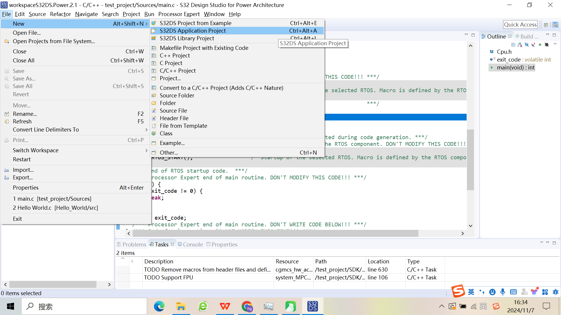
- 点击File->New->S32DS Application Project创建空白工程**。**
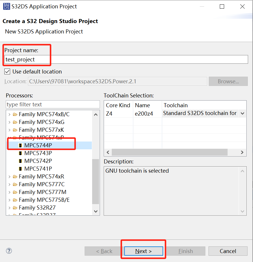
- 接着弹出如下工程配置界面。填写Project name工程名,Processors选择MPC5744P,点击Next。
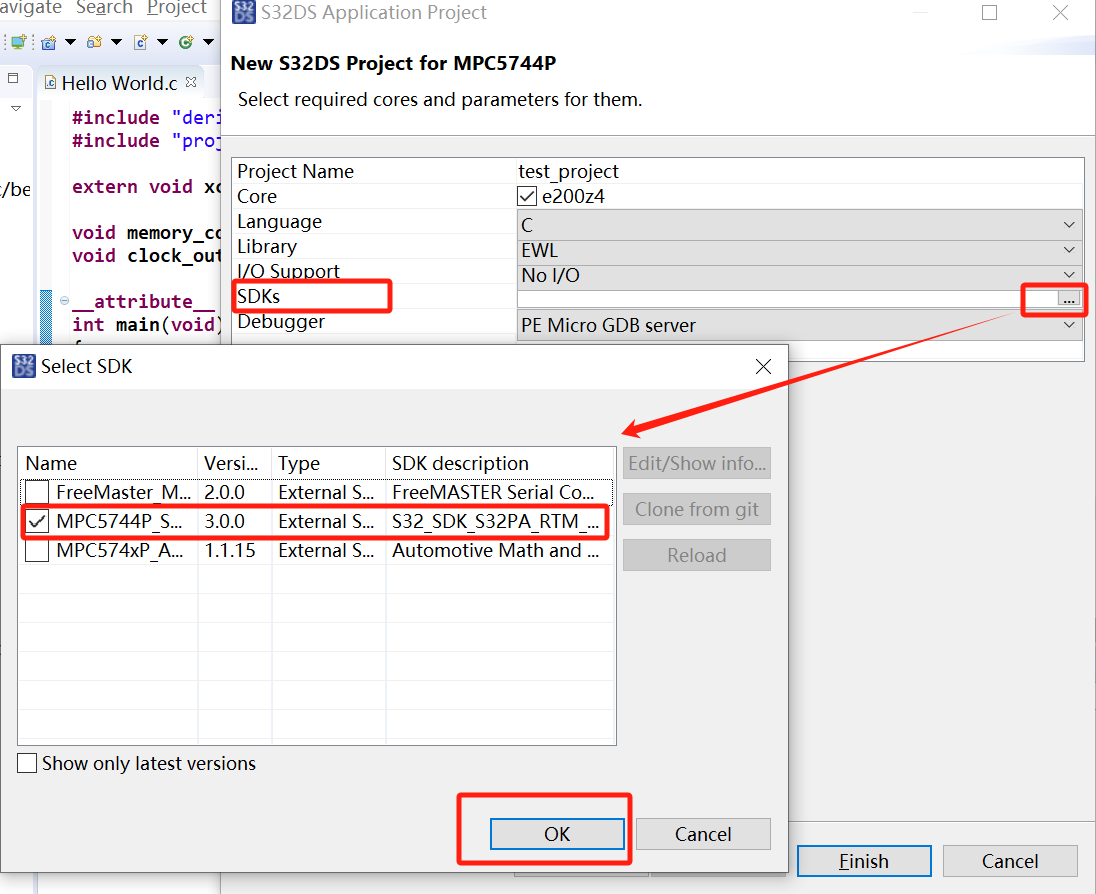
- 选择SDKs的版本,点击OK,如下图。
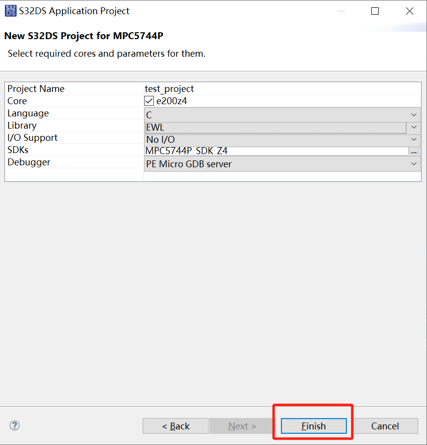
- 点击Finish。
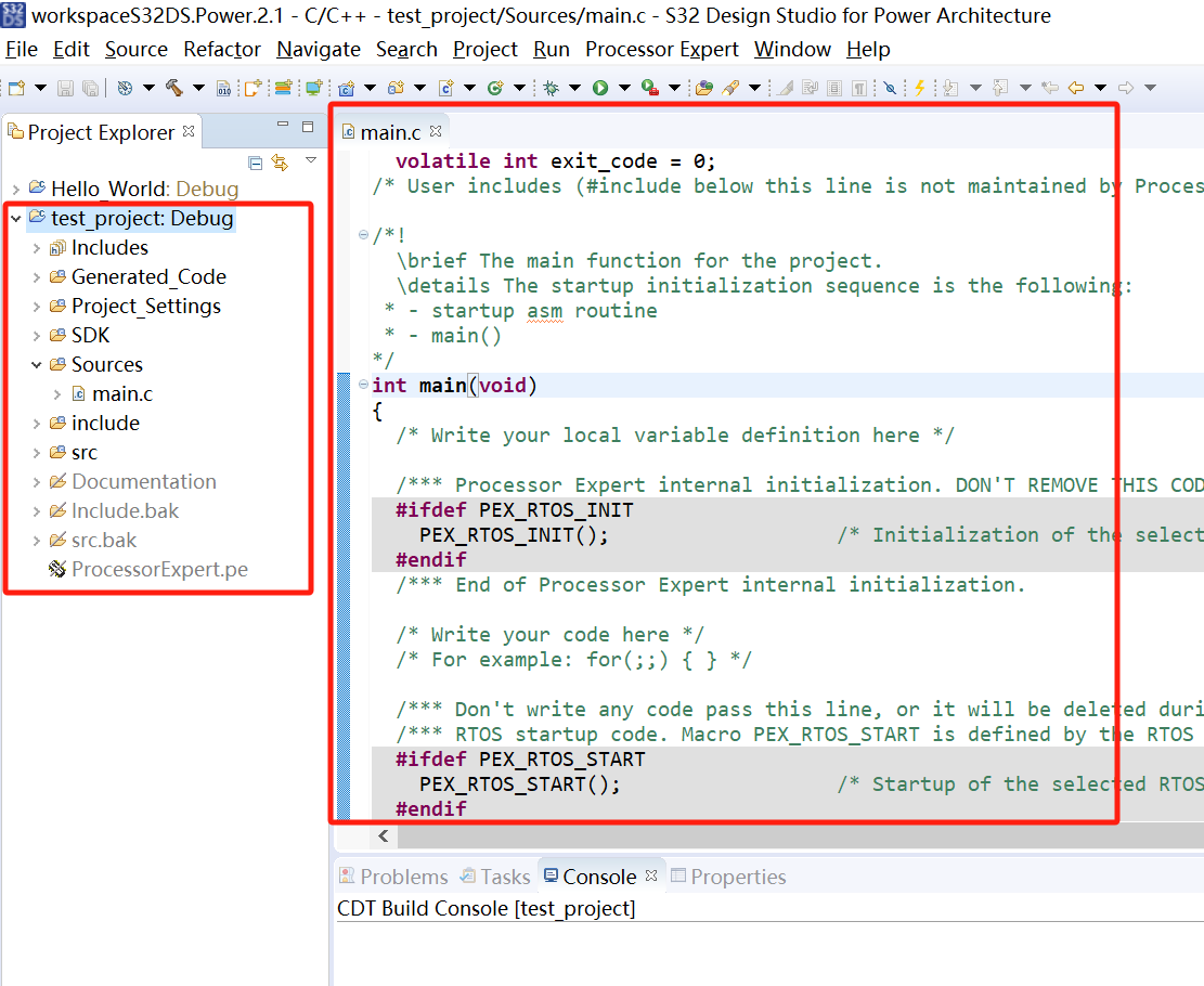
- 新建工程成功,如下图。
二、Processor Expert可视化界面配置
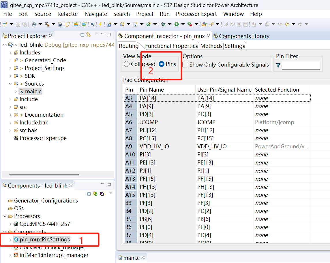
- 我们可以通过图形界面配置进行驱动代码的生成。点击主菜单区域的Processor Expert按钮,选择Show Views,弹出图形化界面,此时,我们可以通过图形界面对外设(GPIO、ADC、CAN等)进行配置。

- 双击pin_mux,选中Component Inspector界面,然后在Routing界面选中Pins,打开引脚的配置界面。在这个界面我们来设置GPIO的属性。
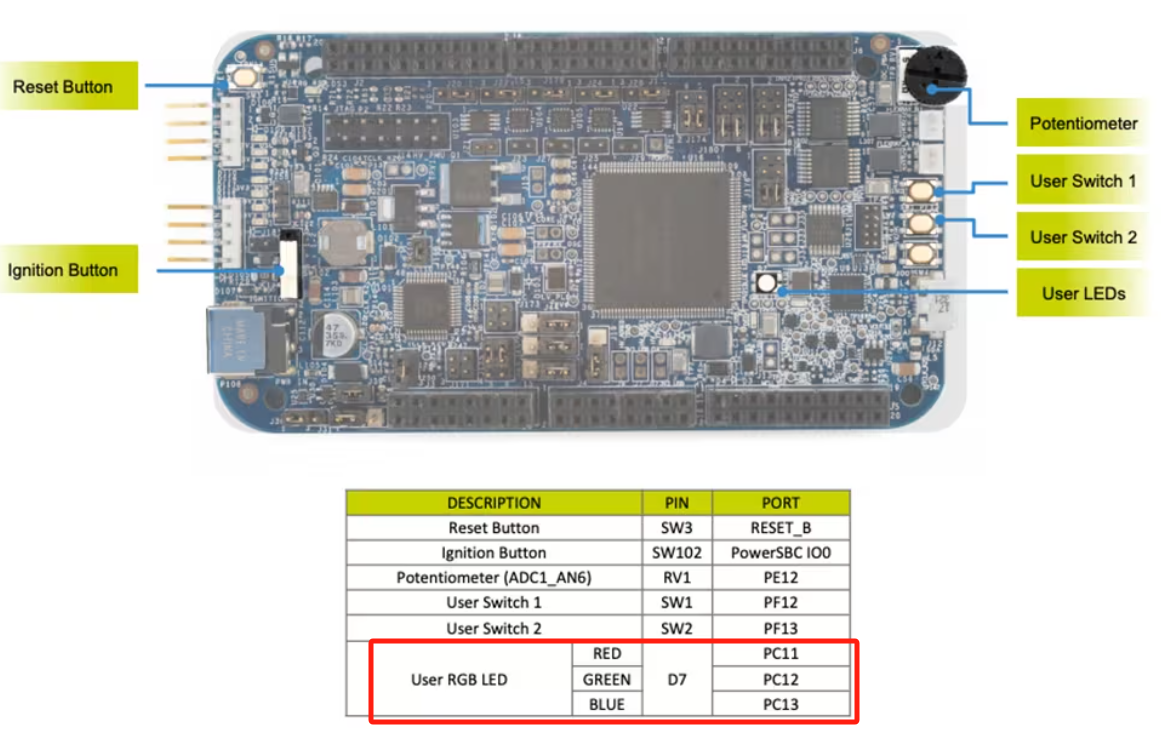
- 参考官方的开发板引脚图,我们知道Led的控制引脚分别为PC11(红灯),PC12(绿灯),PC13(蓝灯)。
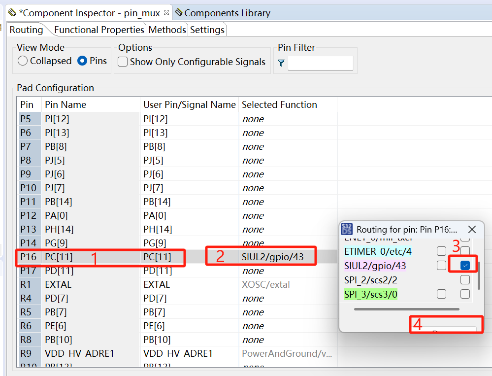
- 这里我们对PC11进行测试。先通过Pin Name找到PC11,然后在Selected Function栏点击选择SIUL2/gpio/43,勾选output direction,点击完成。这样就完成了将PC11配置为GPIO输出模式。
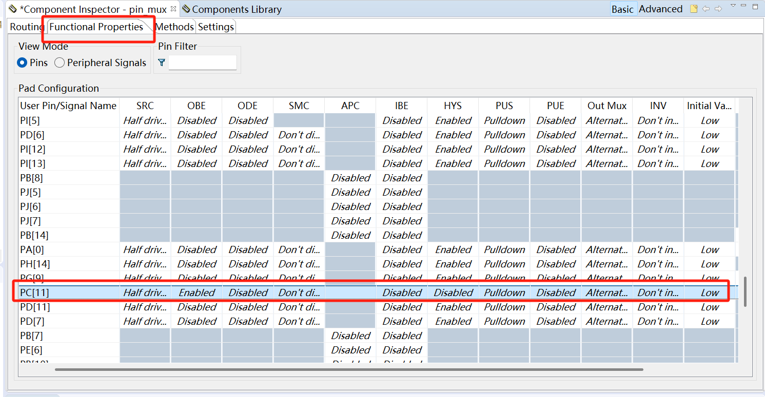
- 点击Functional Properties界面,这里是对GPIO的属性配置,可以配置输入输出模式、初始电平状态等。在这里我选择默认模式,然后点击保存,将整个项目保存一下。
三、代码生成
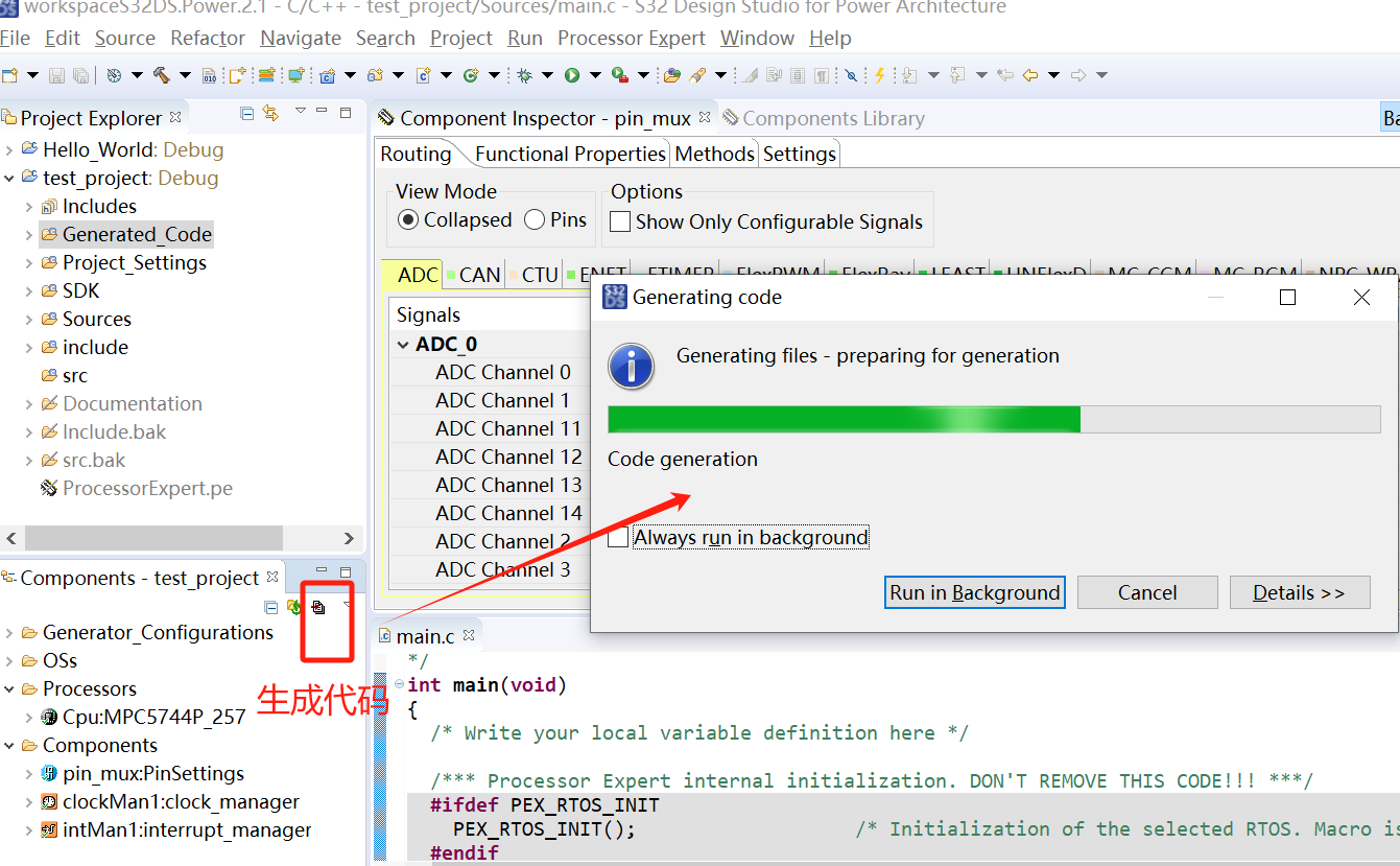
- 配置完成并保存后,开始生成对应配置的驱动代码。点击Components区的生成代码按钮,开始生成代码。
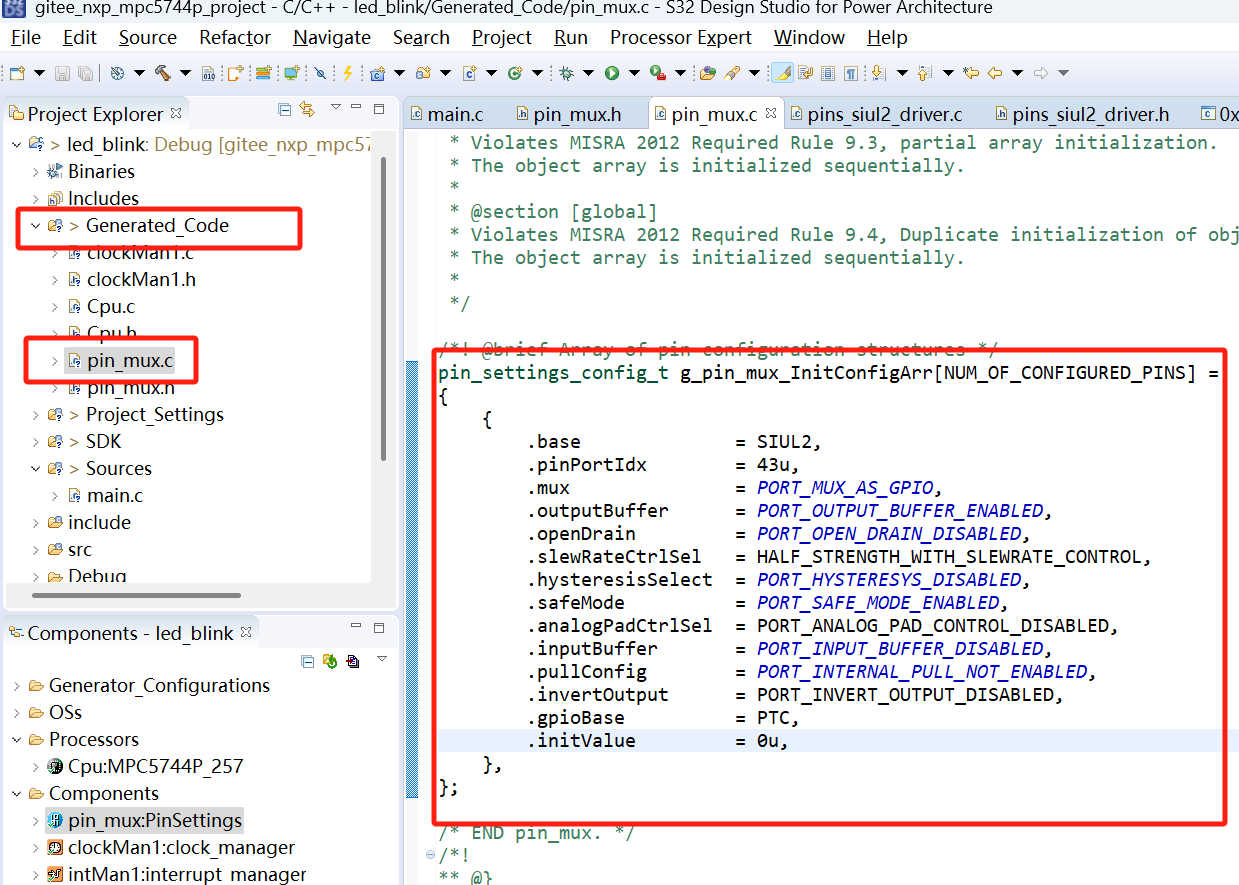
- 代码生成成功,如下图。刚才配置了1个GPIO,这里就有了对1个GPIO口配置数组。
四、代码调用
驱动代码生成后,我们需要在main.c中调用生成的驱动代码,才能够实现功能。
- main.c代码示例:
/*
 * Copyright (c) 2013 - 2015, Freescale Semiconductor, Inc.
 * Copyright 2016-2017 NXP
 * All rights reserved.
 *
 * THIS SOFTWARE IS PROVIDED BY NXP "AS IS" AND ANY EXPRESSED OR
 * IMPLIED WARRANTIES, INCLUDING, BUT NOT LIMITED TO, THE IMPLIED WARRANTIES
 * OF MERCHANTABILITY AND FITNESS FOR A PARTICULAR PURPOSE ARE DISCLAIMED.
 * IN NO EVENT SHALL NXP OR ITS CONTRIBUTORS BE LIABLE FOR ANY DIRECT,
 * INDIRECT, INCIDENTAL, SPECIAL, EXEMPLARY, OR CONSEQUENTIAL DAMAGES
 * (INCLUDING, BUT NOT LIMITED TO, PROCUREMENT OF SUBSTITUTE GOODS OR
 * SERVICES; LOSS OF USE, DATA, OR PROFITS; OR BUSINESS INTERRUPTION)
 * HOWEVER CAUSED AND ON ANY THEORY OF LIABILITY, WHETHER IN CONTRACT,
 * STRICT LIABILITY, OR TORT (INCLUDING NEGLIGENCE OR OTHERWISE) ARISING
 * IN ANY WAY OUT OF THE USE OF THIS SOFTWARE, EVEN IF ADVISED OF
 * THE POSSIBILITY OF SUCH DAMAGE.
 */
/* ###################################################################
**     Filename    : main.c
**     Processor   : MPC574xP
**     Abstract    :
**         Main module.
**         This module contains user's application code.
**     Settings    :
**     Contents    :
**         No public methods
**
** ###################################################################*/
/*!
** @file main.c
** @version 01.00
** @brief
**         Main module.
**         This module contains user's application code.
*/
/*!
**  @addtogroup main_module main module documentation
**  @{
*/
/* MODULE main */


/* Including necessary module. Cpu.h contains other modules needed for compiling.*/
#include "Cpu.h"

volatile int exit_code = 0;
/* User includes (#include below this line is not maintained by Processor Expert) */

/*!
  \brief The main function for the project.
  \details The startup initialization sequence is the following:
 * - startup asm routine
 * - main()
*/
int main(void)
{
    /* Write your local variable definition here */

    /*** Processor Expert internal initialization. DON'T REMOVE THIS CODE!!! ***/
    #ifdef PEX_RTOS_INIT
    PEX_RTOS_INIT();                   /* Initialization of the selected RTOS. Macro is defined by the RTOS component. */
    #endif
    /*** End of Processor Expert internal initialization.                    ***/

    /* Write your code here */
    /* For example: for(;;) { } */
    /* Initialize and configure pins */
    PINS_DRV_Init(NUM_OF_CONFIGURED_PINS, g_pin_mux_InitConfigArr);

    uint32_t count = 0;
    for(;;)
    {
        count++;
        if(count>800000)
        {
            count=0;
            PINS_DRV_TogglePins(PTC, (1 << 11));
        }
    }

    /*** Don't write any code pass this line, or it will be deleted during code generation. ***/
    /*** RTOS startup code. Macro PEX_RTOS_START is defined by the RTOS component. DON'T MODIFY THIS CODE!!! ***/
    #ifdef PEX_RTOS_START
    PEX_RTOS_START();                  /* Startup of the selected RTOS. Macro is defined by the RTOS component. */
    #endif
    /*** End of RTOS startup code.  ***/
    /*** Processor Expert end of main routine. DON'T MODIFY THIS CODE!!! ***/
    for(;;) {
        if(exit_code != 0) {
            break;
        }
    }
    return exit_code;
    /*** Processor Expert end of main routine. DON'T WRITE CODE BELOW!!! ***/
} /*** End of main routine. DO NOT MODIFY THIS TEXT!!! ***/

/* END main */
/*!
** @}
*/
/*
** ###################################################################
**
**     This file was created by Processor Expert 10.1 [05.21]
**     for the NXP C55 series of microcontrollers.
**
** ###################################################################
*/
其中:
1)PINS_DRV_Init(NUM_OF_CONFIGURED_PINS, g_pin_mux_InitConfigArr); //是对PIN引脚的初始化配置。
2)PINS_DRV_TogglePins(PTC, (1 << 11)); //是对PC11引脚的toggle。
- 至此,main.c中已经将生成的代码调用起来了。我们可以将代码下载进开发板中,可以看到开发板的Led灯会显示红色闪烁的状态。


 1537
1537

 被折叠的 条评论
为什么被折叠?
被折叠的 条评论
为什么被折叠?
 到【灌水乐园】发言


