


 本文介绍了两种利用STM32F103的串口IDLE中断和DMA功能接收不定长数据的方法,适用于多种通信协议,如MODBUS、PPI和GPS数据接收。第一种方法通过配置DMA接收和空闲中断,第二种方法则直接利用RXNE和IDLE中断配合操作,简化了数据接收判断过程。
现在有很多数据处理都要用到不定长数据,而单片机串口的RXNE中断一次只能接收一个字节的数据,没有缓冲区,无法接收一帧多个数据,现提供两种利用串口IDLE空闲中断的方式接收一帧数据,方法如下:
方法1:实现思路:采用STM32F103的串口1,并配置成空闲中断IDLE模式且使能DMA接收,并同时设置接收缓冲区和初始化DMA。那么初始化完成之后,当外部给单片机发送数据的时候,假设这帧数据长度是200个字节,那么在单片机接收到一个字节的时候并不会产生串口中断,而是DMA在后台把数据默默地搬运到你指定的缓冲区里面。当整帧数据发送完毕之后串口才会产生一次中断,此时可以利用DMA_GetCurrDataCounter();函数计算出本次的数据接受长度,从而进行数据处理。
应用对象:适用于各种串口相关的通信协议,如:MODBUS,PPI ;还有类似于GPS数据接收解析,串口WIFI的数据接收等,都是很好的应用对象。
关键代码分析:
usart.H
#ifndef __USART_H
#define __USART_H
#include "stdio.h"
#include "sys.h"

#define DMA_Rec_Len 200      //定义一个长度为200个字节的数据缓冲区。(建议定义的长度比你可能接收到的最长单帧数据长度长!)
void uart_init(u32 bound);
void MYDMA_Enable(DMA_Channel_TypeDef*DMA_CHx);

#endif
usart.C
//初始化IO 串口1
//bound:波特率
void uart_init(u32 bound)
{
    //GPIO端口设置
    GPIO_InitTypeDef GPIO_InitStructure;
    USART_InitTypeDef USART_InitStructure;
    NVIC_InitTypeDef NVIC_InitStructure;
    DMA_InitTypeDef DMA_InitStructure;

   RCC_APB2PeriphClockCmd(RCC_APB2Periph_USART1|RCC_APB2Periph_GPIOA,ENABLE); //使能USART1,GPIOA时钟
   RCC_AHBPeriphClockCmd(RCC_AHBPeriph_DMA1, ENABLE); //使能DMA传输
   RCC_APB1PeriphClockCmd(RCC_APB1Periph_USART2,ENABLE);//使能USART2时钟

   USART_DeInit(USART1);  //复位串口1
   //USART1_TX   PA.9
    GPIO_InitStructure.GPIO_Pin = GPIO_Pin_9; //PA.9
    GPIO_InitStructure.GPIO_Speed = GPIO_Speed_50MHz;
    GPIO_InitStructure.GPIO_Mode = GPIO_Mode_AF_PP; //复用推挽输出
    GPIO_Init(GPIOA, &GPIO_InitStructure); //初始化PA9

    //USART1_RX  PA.10
    GPIO_InitStructure.GPIO_Pin = GPIO_Pin_10;
    GPIO_InitStructure.GPIO_Mode = GPIO_Mode_IN_FLOATING;//浮空输入
    GPIO_Init(GPIOA, &GPIO_InitStructure);  //初始化PA10

    //Usart1 NVIC 配置
    NVIC_InitStructure.NVIC_IRQChannel = USART1_IRQn;
    NVIC_InitStructure.NVIC_IRQChannelPreemptionPriority=3 ;//抢占优先级3
    NVIC_InitStructure.NVIC_IRQChannelSubPriority = 3; //子优先级3
    NVIC_InitStructure.NVIC_IRQChannelCmd = ENABLE; //IRQ通道使能
    NVIC_Init(&NVIC_InitStructure); //根据指定的参数初始化VIC寄存器

   //USART 初始化设置
  USART_InitStructure.USART_BaudRate = bound;
  USART_InitStructure.USART_WordLength = USART_WordLength_8b;//字长为8位数据格式
  USART_InitStructure.USART_StopBits = USART_StopBits_1;//一个停止位
  USART_InitStructure.USART_Parity = USART_Parity_No;//无奇偶校验位
  USART_InitStructure.USART_HardwareFlowControl =USART_HardwareFlowControl_None;//无硬件数据流控制
  USART_InitStructure.USART_Mode = USART_Mode_Rx | USART_Mode_Tx; //收发模式

    USART_Init(USART1, &USART_InitStructure); //初始化串口
    USART_ITConfig(USART1, USART_IT_IDLE, ENABLE);//开启空闲中断
    USART_DMACmd(USART1,USART_DMAReq_Rx,ENABLE);   //使能串口1 DMA接收
    USART_Cmd(USART1, ENABLE);                   //使能串口

    //相应的DMA配置
  DMA_DeInit(DMA1_Channel5);   //将DMA的通道5寄存器重设为缺省值  串口1对应的是DMA通道5
  DMA_InitStructure.DMA_PeripheralBaseAddr = (u32)&USART1->DR; //DMA外设usart基地址
  DMA_InitStructure.DMA_MemoryBaseAddr = (u32)DMA_Rece_Buf;  //DMA内存基地址
  DMA_InitStructure.DMA_DIR = DMA_DIR_PeripheralSRC;  //数据传输方向,从外设读取发送到内存
  DMA_InitStructure.DMA_BufferSize = DMA_Rec_Len;  //DMA通道的DMA缓存的大小
  DMA_InitStructure.DMA_PeripheralInc = DMA_PeripheralInc_Disable; //外设地址寄存器不变
  DMA_InitStructure.DMA_MemoryInc = DMA_MemoryInc_Enable;  //内存地址寄存器递增
  DMA_InitStructure.DMA_PeripheralDataSize = DMA_PeripheralDataSize_Byte; //数据宽度为8位
  DMA_InitStructure.DMA_MemoryDataSize = DMA_MemoryDataSize_Byte; //数据宽度为8位
  DMA_InitStructure.DMA_Mode = DMA_Mode_Normal;  //工作在正常缓存模式
  DMA_InitStructure.DMA_Priority = DMA_Priority_Medium; //DMA通道 x拥有中优先级
  DMA_InitStructure.DMA_M2M = DMA_M2M_Disable;  //DMA通道x没有设置为内存到内存传输
  DMA_Init(DMA1_Channel5, &DMA_InitStructure);  //根据DMA_InitStruct中指定的参数初始化DMA的通道

    DMA_Cmd(DMA1_Channel5, ENABLE);  //正式驱动DMA传输
}

//重新恢复DMA指针
void MYDMA_Enable(DMA_Channel_TypeDef*DMA_CHx)
{
	DMA_Cmd(DMA_CHx, DISABLE );  //关闭USART1 TX DMA1所指示的通道
 	DMA_SetCurrDataCounter(DMA_CHx,DMA_Rec_Len);//DMA通道的DMA缓存的大小
 	DMA_Cmd(DMA_CHx, ENABLE);  //打开USART1 TX DMA1所指示的通道
}

//发送len个字节
//buf:发送区首地址
//len:发送的字节数
void Usart1_Send(u8 *buf,u8 len)
{
	u8 t;
  	for(t=0;t<len;t++)		//循环发送数据
	{
		while(USART_GetFlagStatus(USART1, USART_FLAG_TC) == RESET);
		USART_SendData(USART1,buf[t]);
	}
	while(USART_GetFlagStatus(USART1, USART_FLAG_TC) == RESET);
}

//串口中断函数
void USART1_IRQHandler(void)                //串口1中断服务程序
{

     if(USART_GetITStatus(USART1, USART_IT_IDLE) != RESET) //接收中断(接收到的数据必须是0x0d 0x0a结尾)
      {
          USART_ReceiveData(USART1);//读取数据注意:这句必须要,否则不能够清除中断标志位。
          Usart1_Rec_Cnt =DMA_Rec_Len-DMA_GetCurrDataCounter(DMA1_Channel5); //算出接本帧数据长度

         //***********帧数据处理函数************//
          printf ("Thelenght:%d\r\n",Usart1_Rec_Cnt);
          printf ("The data:\r\n");
          Usart1_Send(DMA_Rece_Buf,Usart1_Rec_Cnt);
         printf ("\r\nOver! \r\n");
        //*************************************//
         USART_ClearITPendingBit(USART1,USART_IT_IDLE);         //清除中断标志
         MYDMA_Enable(DMA1_Channel5);                  //恢复DMA指针,等待下一次的接收
     }

}
方法2:实现思路:直接利用stm32的RXNE和IDLE中断进行接收不定字节数据。
基本知识:
IDLE中断什么时候发生?
IDLE就是串口收到一帧数据后,发生的中断。什么是一帧数据呢?比如说给单片机一次发来1个字节,或者一次发来8个字节,这些一次发来的数据,就称为一帧数据,也可以叫做一包数据。
如何判断一帧数据结束,就是我们今天讨论的问题。因为很多项目中都要用到这个,因为只有接收到一帧数据以后,你才可以判断这次收了几个字节和每个字节的内容是否符合协议要求。
看了前面IDLE中断的定义,你就会明白了,一帧数据结束后,就会产生IDLE中断。
如何配置好IDLE中断?
下面我们就配置好串口IDLE中断吧。
这是串口CR1寄存器,其中,对bit4写1开启IDLE中断,对bit5写1开启接收数据中断。(注意:不同系列的STM32,对应的寄存器位可能不同)
RXNE中断和IDLE中断的区别?
当接收到1个字节,就会产生RXNE中断,当接收到一帧数据,就会产生IDLE中断。比如给单片机一次性发送了8个字节,就会产生8次RXNE中断,1次IDLE中断。
这是状态寄存器,当串口接收到数据时,bit5就会自动变成1,当接收完一帧数据后,bit4就会变成1.
需要注意的是,在中断函数里面,需要把对应的位清0,否则会影响下一次数据的接收。比如RXNE接收数据中断,只要把接收到的一个字节读出来,就会清除这个中断**。IDLE中断,如何是F0系列的单片机,需要用ICR寄存器来清除,如果是F1系列的单片机,清除方法是“先读SR寄存器,再读DR寄存器”。**(我怎么知道?手册上写的)
下面以STM32F103为例给出源程序。
我们先来看程序中的主要部分。
串口初始化函数片段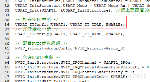
串口中断函数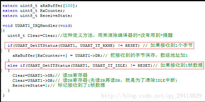
串口中断函数里面,最重要的两条语句,就是上图中圈出来的两条语句。第一条语句用来判断是否接收到1个字节,第二条语句用来判断是否接收到1帧数据。(是不是感觉超级方便?妈妈再也不用担心我如何判断是否接收完1帧数据了。)
主函数
这个主函数,是用来验证接收的正确性的。RxCounter表示的是这一帧数据有几个字节,接收完一帧数据,会在中断函数里面把ReceiveState置1,然后,通过串口把接收到的数据发送回串口。这样,既验证了接收了多少字节的正确性,又验证了接收到的数据是否正确。
两个程序代码均采用stm32f103zet6测试过,完全没问题。
参考文章:http://www.51hei.com/bbs/dpj-39885-1.html(STM32串口接收不定长数据原理与源程序)
STM32使用串口IDLE中断的两种接收不定长数据的方式


 3173
3173


 到【灌水乐园】发言


