


GPIO的学习
结合视频内容,根据数据手册,我对GPIO的使用做了一些总结与理解。
1.什么是GPIO
GPIO(General purpose intput output)是通用输入输出端口的简称,可以通过软件来控制其输入和输出。STM32芯片的GPIO引脚与外部设备连接起来,从而实现与外部通讯、控制以及数据采集的功能。
2.STM32引脚分类
电源管脚、晶振管脚、复位管脚、下载管脚、BOOT管脚、GPIO管脚。
3.GPIO基本结构
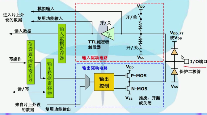
1.输出控制电路:
推挽模式:若输出控制为高电平,则P-MOS导通,N-MOS截止,I/O端口输出高电平。若输出控制为低电平,则P-MOS截止,N-MOS导通,I/O端口输出低电平。
开漏模式:无论输出控制为什么,P-MOS均为截止,若输出控制为低电平,则N-MOS导通,I/O端口输出高电平。此时若想让I/O端口输出高电平,则必须在II/O端口外接一个上拉电阻,输出的电平高低取决于上拉电阻。(类似于C51的P0)
2. 输出数据寄存器(GPIOx_ODR)
3. TTL施密特触发器:可将一些模拟信号最终转化为数字信号。
4.复用功能输出的信号来自片上外设的数据。
4.GPIO的深入学习
1. 读取GPIO端口数据函数
GPIO_ReadInputDataBit(GPIOx,GPIO_Pin_y);//读取单个输入端口的数据
GPIO_ReadInputData(GPIOx);//读取整个输入端口的数据
GPIO_ReadOutputDataBit(GPIOx, GPIO_Pin_y);//读取单个输出端口的数据
GPIO_ReadOutputData (GPIOx);//读取整个输入出端口的位数据
这4个库函数是用来直接读取端口数据的,其中x:A-G y: 0~15
上面的函数实现的是读取当前GPIO口或位的输入输出数据,库函数没有什么可说的。
但这几个函数涉及到下面两个寄存器:
端口数据输入寄存器(GPIOA_IDR~GPIOG_IDR);
端口数据输出寄存器(GPIOA_ODR~GPIOG_ODR);
这两个寄存器都是16位的,高16位保留,读取值为0,低16位代表着对应GPIO端口位[15:0]的状态,偏移值位0cH,具体地址可参考寄存器表。上面的库函数读取Data就是读取这两个寄存器中选定那个的低16位,读取DataBit就是读取选定寄存器16位中的任意选定位。
2 . 写入GPIO端口数据函数
GPIO_WriteBit(GPIOx, GPIO_Pin_y,BIT_SET/BIT_RESET);//置位或者复位单个输出端口的数据
GPIO_Write(GPIOx, 0x1111);//置位或者复位整个输出端口的数据
其中x:A-G y: 0~15
这两个函数是对GPIO_SetBits和GPIO_ResetBits的补充,可以满足对多个端口同时设置状态的特性。
端口复位置位寄存器(GPIOA_BSRR~GPIOG_BSRR) ,32bit复位置位寄存器,w(只写,下同),
[31~16]写0无效,写1对应GPIOx_ODR位置0
[15~0]写0无效,写1对应GPIOx_ODR位置1
端口复位寄存器(GPIOA_BRR~GPIOG_BRR),32bit复位寄存器w
高16位保留,低16位
[15~0]写0无效,写1对应GPIOx_ODR位置0 若GPIOx_BRR和GPIOx_BSRR同时设置,以GPIOx_BSRR为准。
3. GPIO功能锁存函数
GPIO_PinLockConfig(GPIOx, GPIO_Pin_y);//锁存选择端口配置寄存器的对应位
端口锁存寄存器(GPIOA_LCKR~GPIOG_LCKR),32bit寄存器,高16位保留,低16可随时读出,1代表对应配置位被激活锁存,0代表可以被激活,激活是有固定的写入顺序的。锁存是不能乱用的,如果锁存了一个端口的功能寄存器,那么在下次系统复位前,端口的功能就不可更改,这在某些情况下是有利的,特别是在程序中如果重新定义某些GPIO口的功能时,在确定其中某一GPIO端口在整个系统运行中状态保持不变,锁存就避免误修改,但是如果锁存的GPIO在后续的代码段中有不同的功能,就会无法修改,产生错误。因此锁存和GPIO_StructInit, GPIO_DeInit,GPIO_AFIODeInit这些初始化函数一样,使用前要考虑清楚。
4.GPIO特殊功能函数
函数**GPIO_EventOutputConfig(GPIO_PortSourceGPIOx,GPIO_PinSourcey);**事件输出。
函数GPIO_EXTILineConfig(GPIO_PortSourceGPIOx, GPIO_PinSourcey); 外设端口作为中断线号输入
这两个函数我就不多说了,在EXTI-NVIC中会有详细解释。
rtSourceGPIOx, GPIO_PinSourcey);** 外设端口作为中断线号输入
这两个函数我就不多说了,在EXTI-NVIC中会有详细解释。
函数**GPIO_PinRemapConfig(u32GPIO_Remap, FunctionalState NewState);**改变指定管脚的映射,很多复用功能的引出脚可以通过重映射,从不同的I/O管脚引出,即复用功能的引出脚位是可通过程序改变的。就是上面库函数。


 4461
4461

 被折叠的 条评论
为什么被折叠?
被折叠的 条评论
为什么被折叠?
 到【灌水乐园】发言


