


Grid Factory Routines
MRST contains several grid-factory routines for creating structured grids, including regular Cartesian, rectilinear, and curvilinear grids, as well as unstructured grids, including Delaunay triangulations and Voronoi grids, and 3D grids created by extrusion of 2D shapes. Most important, however, is the support for the industry-standard corner-point grids given by the Eclipse input deck. The figure below shows several examples of grids and the commands necessary to create and display them.
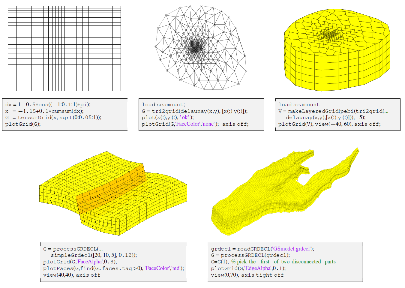
Examples of grids and the MRST statements necessary to create them. The data file seamount.mat is distributed with MATLAB; the file GSmodel.grdecl is not yet publicly available.
Example: Hybrid Grid
As an example of MRST's capability for handling unstructured grids, we have constructed a constrained Voronoi grid from an initial distribution of points. With the built-in MATLAB command voronoin, it is possible to construct uniform grids from uniform distributions of points. This gives an unstructured areal grid with 4509 cells, which we have further extruded to a faulted model with five layers. The areal grid consist of three parts: A Cartesian grid at the outer boundary, a hexahedral grid in the interior, and a radial grid with exponential radial refinement around the wells. The radial grids have been refined to an inner radius of 0.3m. As in the standard corner-point grid format, the extrusion process is accomplished by assigning pillars to each node in the areal grid. Each grid cell in the extruded grid is given a set of z-coordinates for each of the nodes. The x and y coordinates can be computed from the pillars associated with the cell.
The grid has then been populated with permeability and porosity sampled from Layers 40 through 44 in Model 2 of the 10th SPE Comparative Solution Project (Christie and Blunt, 2001). The permeability field is shown on the left in the figure. The wells are modelled as Dirichlet boundaries with pressures set to 200 bar and 100 bar, respectively, and we compute the pressure and water saturation with a sequentially implicit scheme using time steps of 50 days. For the spatial discretization of the pressure equation, we have used the mimetic method, whereas a standard first-order upwind mobility scheme is used to compute the transport. The oil-water viscosity ratio is 10. The pressure and water saturation is shown after 5000 days of injection in the figure.
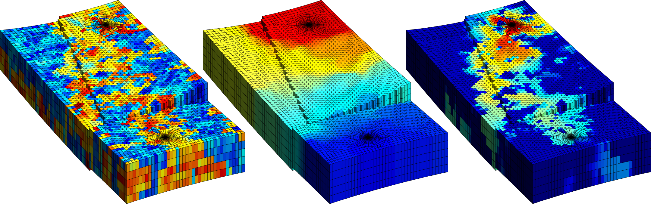
Two-phase flow computed on a pillar grid constructed by extruding an areal grid consisting of structured and unstructured parts: a radially refined grid, a Cartesian grid along the outer boundary, a hexahedral grid in the interior and general polyhedral cells to glue everything together. The plots show permeability (left), pressure field (middle) and water saturation after 5000 days.
来源: http://www.sintef.no/Projectweb/MRST/Gallery/Flexible-gridding/


 2990
2990

 被折叠的 条评论
为什么被折叠?
被折叠的 条评论
为什么被折叠?
 到【灌水乐园】发言


