


 本文详细指导如何配置R1-R4设备间的HDLC、PPP和CHAP封装,构建MGRE环境,实现RIP路由共享,并演示NAT转换。涉及RIP协议、PPP/PAP/CHAP认证、MGRE隧道设置及PC间网络访问。
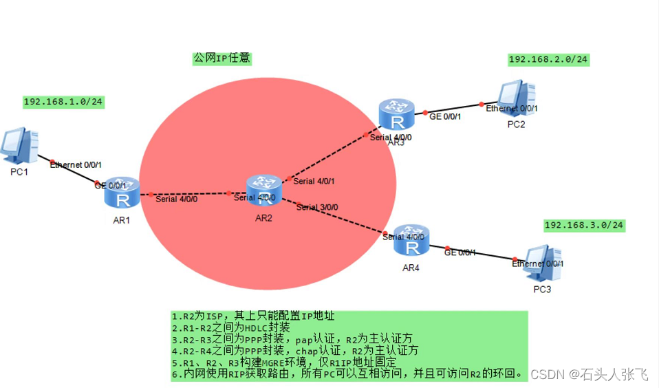
实验要求
1.R2为isp,其上只能配置IP地址
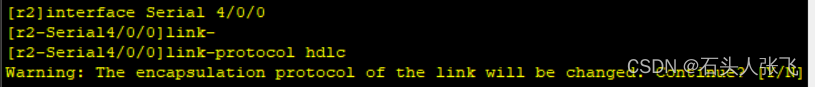
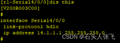
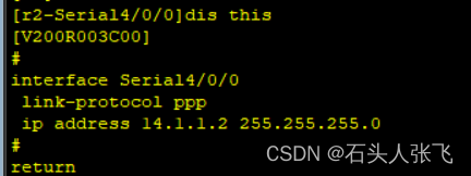
2.R1-R2之间为HDLC封装
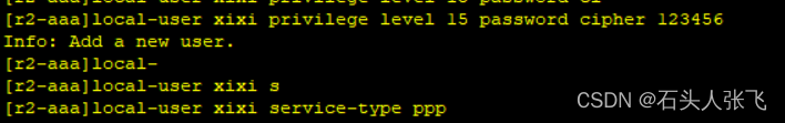
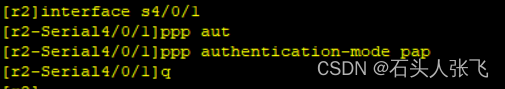
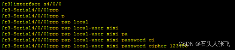
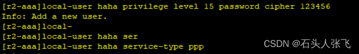
3.R2-R3之间为PPP封装,pap认证,R2为主认证方
4.R2-R4之间为ppp封装,chap认证,R2为主认证方
5.R1 ,R2,R3构建MGRE环境,仅R1 IP地址固定
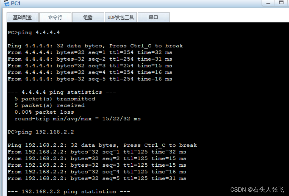
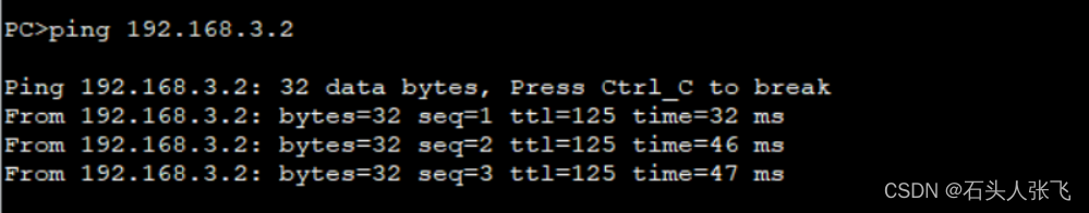
6.内网使用RIP获取路由,所有pc可以互相访问,并且可以访问R2的环回。
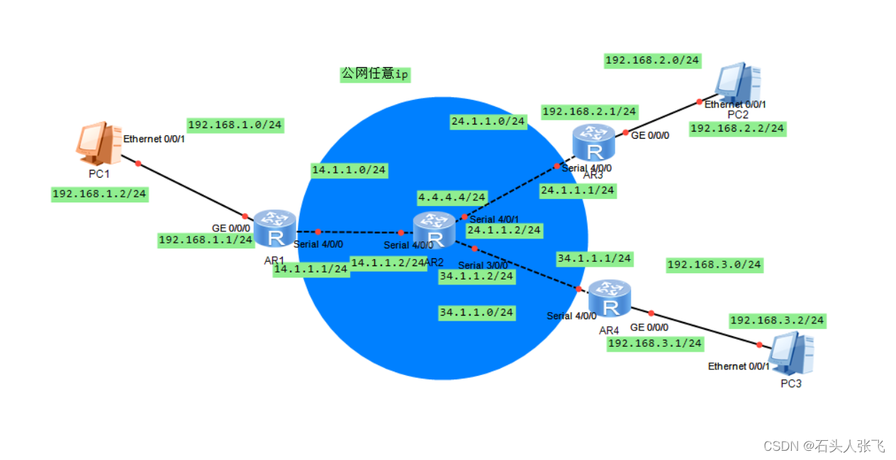
拓扑图
实验分析
先划分好网段 ,配置好接口IP地址,再进行封装和认证
实验拓扑
HDLC封装

ppp封装,pap 认证
ppp封装,chap认证

![]()
构建MGRE环境,R1 IP地址固定
在R1上:R1为中心站点
interface Tunnel0/0/0 创建tunnel口
ip address 10.1.1.1 24 配置接口ip地址
tunnel-protocol gre p2mp 先修改接口模式为多点GRE
source 14.1.1.1 再定义公有的源IP地址
nhrp entry multicast dynamic 本地成为NHRP中心,同时可以进行伪广播
nhrp network-id 100 默认为0号,该网段内所有节点tunnel接口必须为相同域
在R3上:R3为分支站点
interface Tunnel0/0/0
ip address 10.1.1.2 24
tunnel-protocol gre p2mp
source s4/0/0 假设分支站点ip地址不固定
nhrp network-id 100
nhrp entry 10.1.1.1 14.1.1.1 register 分支需要到中心站点注册
在R4上:R4也为分支站点
interface Tunnel0/0/0
ip address 10.1.1.3 24
tunnel-protocol gre p2mp
source s4/0/0
nhrp network-id 100
nhrp entry 10.1.1.1 14.1.1.1 register
RIP获取路由
R1
rip 1 用rip学习
version 2
network 192.168.0.0
network 10.0.0.0
缺省路由 ip route-static 0.0.0.0 0.0.0.0 14.1.1.2
R2
rip 1
version 2
缺省路由
ip route-static 0.0.0.0 0.0.0.0 24.1.1.1
ip route-static 0.0.0.0 0.0.0.0 34.1.1.1
R3
rip 1
version 2
network 192.168.0.0
network 10.0.0.0
缺省路由 ip route-static 0.0.0.0 0.0.0.0 24.1.1.2
R4
rip 1
version 2
network 192.168.0.0
network 10.0.0.0
network 192.168.1.0
缺省路由
ip route-static 0.0.0.0 0.0.0.0 34.1.1.2
ip route-static 192.168.1.0 255.255.255.0 14.1.1.1
最后R1,R2,R3进行NAT进行网络转换
实验验证
PC1
PC2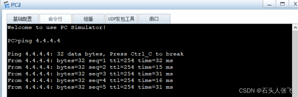
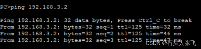
PC3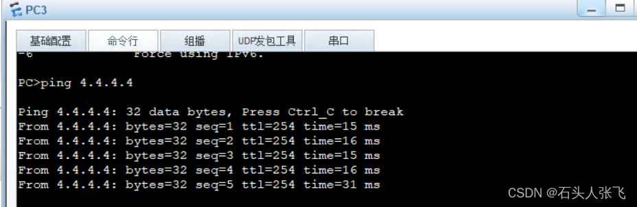


 733
733

 被折叠的 条评论
为什么被折叠?
被折叠的 条评论
为什么被折叠?
 到【灌水乐园】发言


