


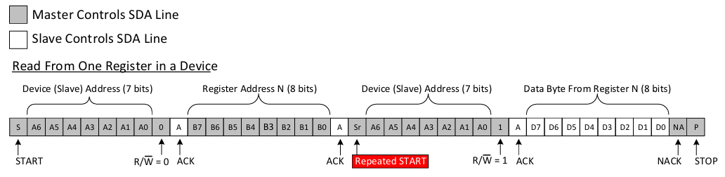
在上一篇文章 详解I2C 的末尾,有这样一张波形图:

这个对应的就是常见的从设备寄存器读数据的波形,只是在写数据时多了一个字节。
通用的从I2C设备读寄存器数据的模式应该是这样的:
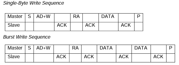
在mpu6050数据表中的9.3 I2C Communications Protocol章节说明了mpu6050的i2c接口协议,符合通用模式。
mpu6050单字节写和加速写序列如下:
mpu6050单字节读和加速读序列如下:
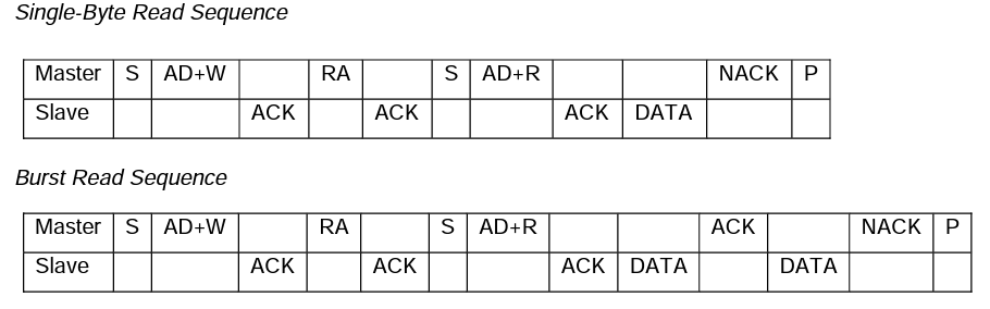
上面的加速写和加速读都是以2个数据字节为例的。
从实例2的波形图可以看出,启动传输后,写了0x12 0x13 0x143个字节,这3个字节后都是NACK,然后是重复起始信号,跟着刚才地址字节0x12+1即0x13,I2C从写转换到读,然后开始读数据字节。
对应代码为:
result = ch347_driver.i2c_set(device_index, 1)
if result:
    print("Success to set I2C speed.")
else:
    print("Failed to set I2C speed.")

result = ch347_driver.i2c_set_delay_ms(device_index, 1)
if result:
    print("Success to set I2C delay.")
else:
    print("Failed to set I2C delay.")


result = ch347_driver.stream_i2c(device_index, b'\x12\x13\x14', 8)
if result:
    print("Success!")
else:
    print("Failed!")
将上面这段代码稍加修改:
result = ch347_driver.i2c_set(device_index, 1)
if result:
    print("Success to set I2C speed.")
else:
    print("Failed to set I2C speed.")

result = ch347_driver.i2c_set_delay_ms(device_index, 1)
if result:
    print("Success to set I2C delay.")
else:
    print("Failed to set I2C delay.")


result = ch347_driver.stream_i2c(device_index, b'\xd0\x75', 1)
if result:
    print("Success! result:", result.hex())
else:
    print("Failed!")
mpu6050模块的地址是0b1101000(AD0 = 0),左移1位得到设备写地址0xd0,读数据时的读地址ch347会自动产生,波形如下:

还没有连接mpu6050模块,所以没有数据返回。现在把mpu6050模块i2c接口连接到ch347模块上,运行程序,结果为:
❯  python test.py
Successfully opened device index: 0
Device Information:
iIndex: 0
DevicePath: \\?\USB#VID_1A86&PID_55DB&MI_02#7&2887B016&0&0002#{5446F048-98B4-4EF0-96E8-27994BAC0D00}
UsbClass: 0
FuncType: 1
DeviceID: USB\VID_1A86&PID_55DB&MI_02#7&2887B016&0&0002#
ChipMode: 1
DevHandle: 912
BulkOutEndpMaxSize: 512
BulkInEndpMaxSize: 512
UsbSpeedType: 1
CH347IfNum: 0
DataUpEndp: 6
DataDnEndp: 6
ProductString:
ManufacturerString:
WriteTimeout: 500
ReadTimeout: 500
FuncDescStr: USB2.0 To SPI&IIC
FirewareVer: 64
<ch347.mDeviceInforS object at 0x000002465A1E63C0>
Version Information:
Driver Version: 35
DLL Version: 34
Device Version: 64
Chip Type: 1
Success to set I2C speed.
Success to set I2C delay.
Success! result: 68
Successfully closed device index: 0
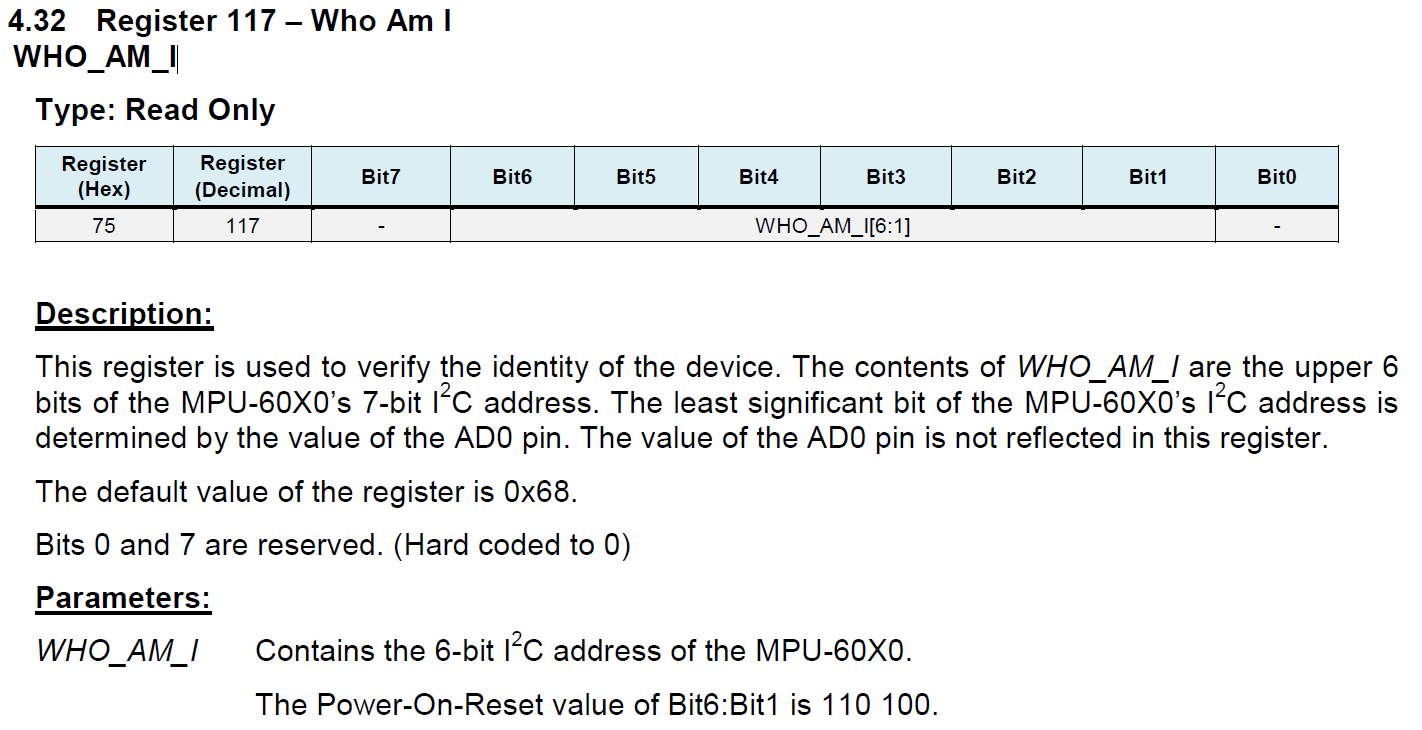
可以看到返回了数据0x68,0x75是’WHO_AM_I’寄存器,默认值为0x68。
完整代码:
import ch347

dll_path = "ch347dlla64.dll"  # Replace with the actual path to the DLL
device_index = 0  # Set the device index according to your requirements

ch347_driver = ch347.CH347Driver(dll_path)

result = ch347_driver.open_device(device_index)
if result:
    print(f"Successfully opened device index: {device_index}")
else:
    print(f"Failed to close device index: {device_index}")

result, device_info = ch347_driver.get_device_info(device_index)
if result:
    print("Device Information:")
    print(f"iIndex: {device_info.iIndex}")
    print(f"DevicePath: {device_info.DevicePath.decode()}")
    print(f"UsbClass: {device_info.UsbClass}")
    print(f"FuncType: {device_info.FuncType}")
    print(f"DeviceID: {device_info.DeviceID.decode()}")
    print(f"ChipMode: {device_info.ChipMode}")
    print(f"DevHandle: {device_info.DevHandle}")
    print(f"BulkOutEndpMaxSize: {device_info.BulkOutEndpMaxSize}")
    print(f"BulkInEndpMaxSize: {device_info.BulkInEndpMaxSize}")
    print(f"UsbSpeedType: {device_info.UsbSpeedType}")
    print(f"CH347IfNum: {device_info.CH347IfNum}")
    print(f"DataUpEndp: {device_info.DataUpEndp}")
    print(f"DataDnEndp: {device_info.DataDnEndp}")
    print(f"ProductString: {device_info.ProductString.decode()}")
    print(f"ManufacturerString: {device_info.ManufacturerString.decode()}")
    print(f"WriteTimeout: {device_info.WriteTimeout}")
    print(f"ReadTimeout: {device_info.ReadTimeout}")
    print(f"FuncDescStr: {device_info.FuncDescStr.decode()}")
    print(f"FirewareVer: {device_info.FirewareVer}")
    print(repr(device_info))
else:
    print("Failed to get device information.")

result, driver_ver, dll_ver, device_ver, chip_type = ch347_driver.get_version(device_index)
if result:
    print("Version Information:")
    print(f"Driver Version: {driver_ver}")
    print(f"DLL Version: {dll_ver}")
    print(f"Device Version: {device_ver}")
    print(f"Chip Type: {chip_type}")
else:
    print("Failed to get version information.")

result = ch347_driver.i2c_set(device_index, 1)
if result:
    print("Success to set I2C speed.")
else:
    print("Failed to set I2C speed.")

result = ch347_driver.i2c_set_delay_ms(device_index, 1)
if result:
    print("Success to set I2C delay.")
else:
    print("Failed to set I2C delay.")


result = ch347_driver.stream_i2c(device_index, b'\xd0\x75', 1)
if result:
    print("Success! result:", result.hex())
else:
    print("Failed!")


# Example usage of CH347CloseDevice
result = ch347_driver.close_device(device_index)
if result:
    print(f"Successfully closed device index: {device_index}")
else:
    print(f"Failed to close device index: {device_index}")
接下来就可以对mpu6050各种功能进行封装,然后在电脑上直接获取传感器数据了。
公众号 | FunIO
微信搜一搜 “funio”,发现更多精彩内容。
个人博客 | blog.boringhex.top


 被折叠的 条评论
为什么被折叠?
被折叠的 条评论
为什么被折叠?
 到【灌水乐园】发言


