小猫爪:S32K3学习笔记06-S32K3之BCTU

1 前言

  大家好,又又又见面了,今天学习了以下S32K3的BCTU模块,BCTU其实就是一个专门的ADC硬件触发器,在ADC的文章中简单的介绍了一下,今天来对齐做个总结,如有错误的地方,希望大家留言指正。

  BCTU的功能实现如下所示:
在这里插入图片描述
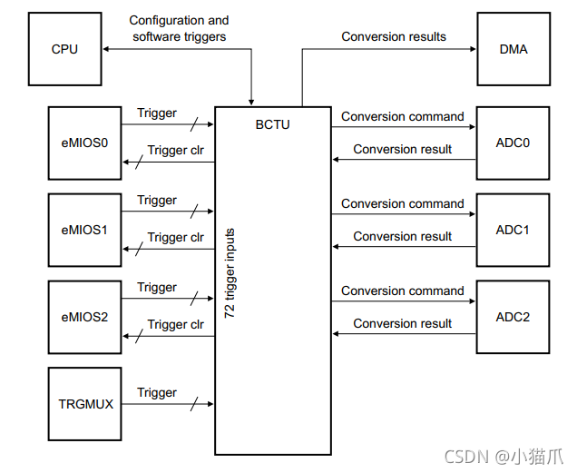
  BCTU接受来自CPU,eMIOS, TRGMUX的信号后产生ADC触发信号去触发ADC开始转换,ADC转换完成后再把结果返回给BCTU,BCTU可支持DMA搬运。

2 BCTU资源介绍

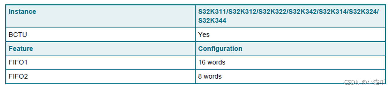
  S32K3全系标配BCTU模块,除了三个结果寄存器之外,BCTU还有两个FIFO用来存储转换结果,并用来支持DMA传输。
在这里插入图片描述

3 功能介绍

  BCTU的功能框图如下:

在这里插入图片描述
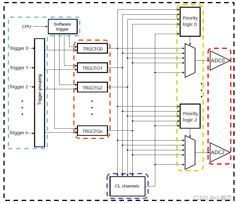
上图非常简单,就不多作废话,下面补充几个上图没有的信息:

  1. BCTU一共支持72个触发信号,对应72个TRGCFG寄存器。
  2. 一个触发信号可以同时并行触发ADC0,ADC1,ADC2开始转换。
  3. K3处于STANDBY模式下, BCTU是不工作的。
  4. 可以通过使用CL来实现一个触发信号来触发一个转换队列。

3.1 触发信号

  上面提到BCTU一共支持72个触发信号,那这72个信号分别是哪些呢?看下表:
在这里插入图片描述
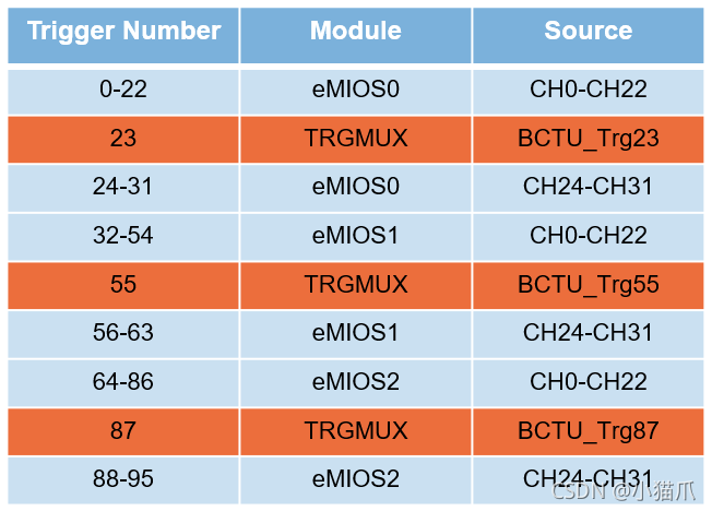
  从表格中可以非常的清楚的看到,大部分都是由eMIOS的输出信号来触发,还有3个则是由TRGMUX触发。

3.2 CL(Conversion list )

  上面提到可以通过CL来实现一个触发信号来触发一个转换队列,其实意思很简单,我们只需要提前配置好这个转换队列,当这个触发信号过来后,BCTU就会根据这个转换队列来依次产生触发信号去触发ADC开始转换。这个队列最大支持32个。
  在这里就不提具体是怎么实现的了,NXP的SDK包提供了非常方便的API借口来实现这个队列初始化功能,感兴趣的小伙伴可以去参考一下K3的RM手册BCTU章节。

3.3 DMA支持

  BCTU的两个FIFO均支持申请DMA传输,我们可以预先设置好FIFO的watermask值,当FIFO里面的数据深度达到watermask值后就会产生DMA触发信号来申请DMA传输。

4 MCAL配置示例

待续。。。。。。

待续。。。。。。

### S32K3 Microcontroller DMA Configuration Tutorial #### Overview of DMA on the S32K3 Series The Direct Memory Access (DMA) feature within the S32K3 series allows data transfer between memory and peripherals without CPU intervention, improving system efficiency. The eDMA module supports multiple channels with flexible arbitration mechanisms to manage concurrent requests effectively[^1]. #### Key Components Involved in DMA Setup For configuring DMA operations specifically involving ADC interfaces: - **Hardware Units**: Two hardware units can be configured as `ADC0` and `ADC1`. Users should configure these based on their specific circuit requirements[^3]. - **Channel Management**: When using multiple ADC channels, only the last channel triggers a DMA request upon completion. After one major loop finishes executing, it automatically loads the next Transfer Control Descriptor (TCD)[^2]. #### Step-by-step Guide for Configuring DMA with ADC To set up DMA transfers from an ADC peripheral: 1. Initialize the ADC modules (`ADC0`, `ADC1`) according to project needs. 2. Configure TCD settings including source address, destination address, block size, etc., ensuring proper alignment with the desired buffer structure. 3. Set up interrupt handlers if necessary to handle events such as end-of-conversion or error conditions. 4. Enable DMA requests by setting appropriate bits in control registers associated with each ADC instance used. 5. Ensure that after completing a major loop, subsequent minor loops are correctly initialized via preloaded TCD entries. ```c // Example C code snippet showing basic setup steps void init_DMA_for_ADC(void){ // Assuming initialization functions exist for simplicity /* Initialize ADC */ ADC_Init(ADC0); /* Prepare TCD structures */ edma_config_t dmaConfig; EDMA_GetDefaultConfig(&dmaConfig); EDMA_Init(DMA_BASE_ADDR, &dmaConfig); /* Create and configure TCDs */ uint8_t tcdIndex = 0; // Choose available index EDMA_CreateHandle(&g_edmaHandle[tcdIndex], DMA_BASE_ADDR, tcdIndex); } ``` This example demonstrates initializing DMA alongside ADC configurations but does not cover all possible scenarios or optimizations which may vary depending on application specifics. --related questions-- 1. How do different types of DMA modes affect performance when interfacing with ADC? 2. What considerations must be taken into account while designing buffers for storing ADC samples through DMA? 3. Can you explain how priority levels influence DMA operation among competing peripherals like UART vs SPI? 4. In what ways could interrupts play a role during continuous acquisition mode enabled by DMA?
评论
添加红包

请填写红包祝福语或标题

红包个数最小为10个

红包金额最低5元

当前余额3.43前往充值 >
需支付:10.00
成就一亿技术人!
领取后你会自动成为博主和红包主的粉丝 规则
hope_wisdom
发出的红包

打赏作者

小猫爪

你的鼓励将是我创作的最大动力

¥1 ¥2 ¥4 ¥6 ¥10 ¥20
扫码支付:¥1
获取中
扫码支付

您的余额不足,请更换扫码支付或充值

打赏作者

实付
使用余额支付
点击重新获取
扫码支付
钱包余额 0

抵扣说明:

1.余额是钱包充值的虚拟货币,按照1:1的比例进行支付金额的抵扣。
2.余额无法直接购买下载,可以购买VIP、付费专栏及课程。

余额充值