


 本文档详细介绍了网络设备的配置过程,包括接口IP配置、静态路由设定、GRE隧道的建立以实现全连MGRE结构,并通过OSPF协议确保全网互通。此外,还涉及了不规则区域的虚连接配置,以及使用NAT允许R4-R6访问外部网络。最后,展示了如何通过telnet从R1远程登录到R6的设置步骤。
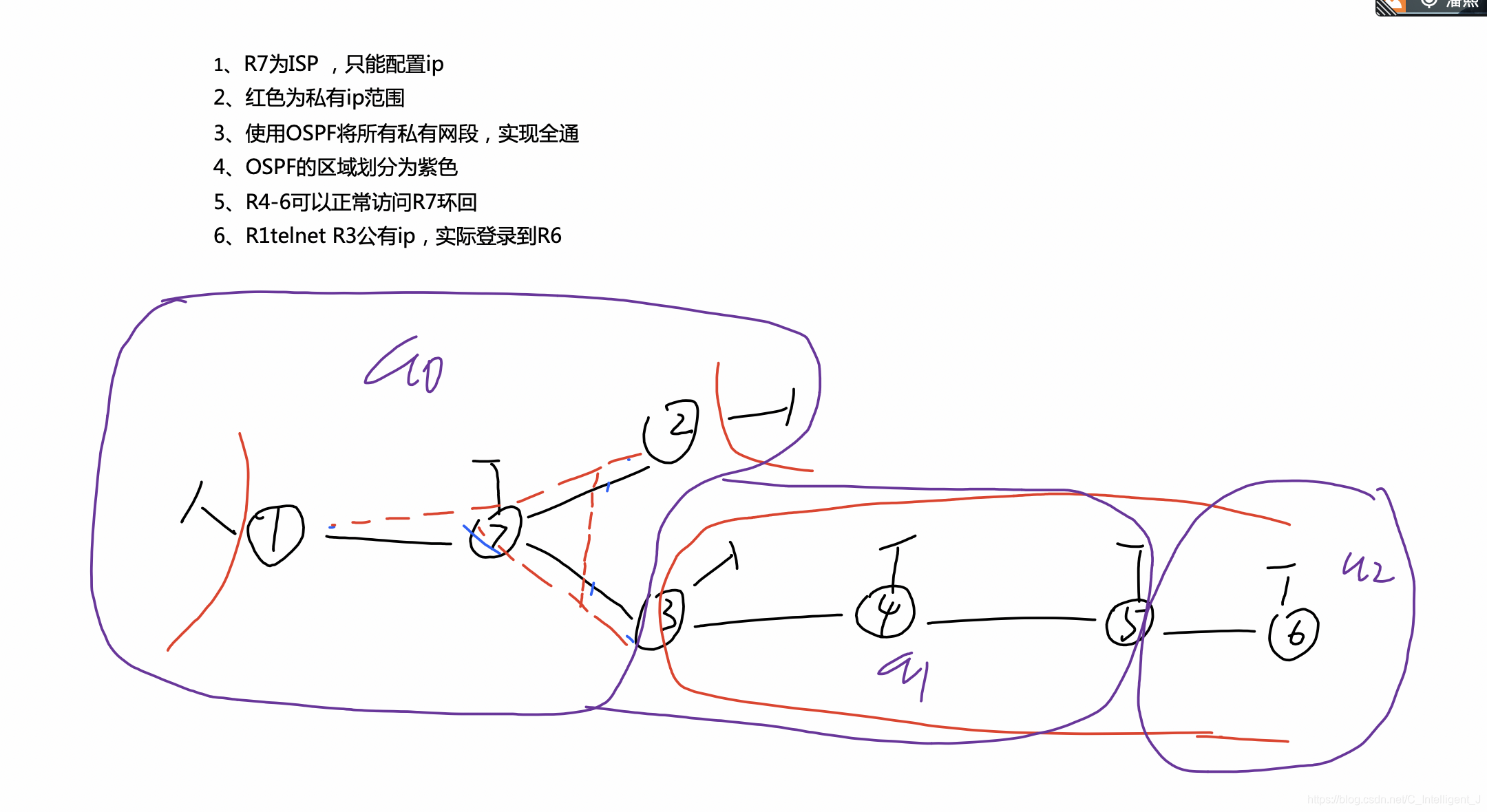
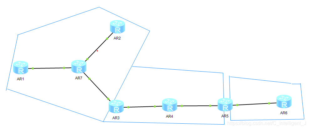
1.接口以及环回口的IP的基础配置
2.配置静态路由指向R7外网
[R1]ip route-static 0.0.0.0 0 17.1.1.7

[R2]ip route-static 0.0.0.0 0 27.1.1.7

[R3]ip route-static 0.0.0.0 0 37.1.1.7

[R4]ip route-static 0.0.0.0 0 34.1.1.3

[R5]ip route-static 0.0.0.0 0 45.1.1.4

[R6]ip route-static 0.0.0.0 0 56.1.1.5
3.设置tunnel口使得R1/2/3为全连MGRE结构
[R1]interface Tunnel 0/0/0
[R1-Tunnel0/0/0]ip address 10.1.1.1 24
[R1-Tunnel0/0/0]tunnel-protocol gre p2mp
[R1-Tunnel0/0/0]source 17.1.1.1
[R1-Tunnel0/0/0]nhrp entry multicast dynamic
[R1-Tunnel0/0/0]nhrp network-id 100
[R1-Tunnel0/0/0]nhrp entry 10.1.1.2 27.1.1.2 register
[R1-Tunnel0/0/0]nhrp entry 10.1.1.3 37.1.1.3 register


[R2]interface Tunnel 0/0/0
[R2-Tunnel0/0/0]ip address 10.1.1.2 24
[R2-Tunnel0/0/0]tunnel-protocol gre p2mp
[R2-Tunnel0/0/0]source 27.1.1.2
[R2-Tunnel0/0/0]nhrp entry multicast dynamic
[R2-Tunnel0/0/0]nhrp network-id 100
[R2-Tunnel0/0/0]nhrp entry 10.1.1.1 17.1.1.1 register
[R2-Tunnel0/0/0]nhrp entry 10.1.1.3 37.1.1.3 register


[R3]interface Tunnel 0/0/0
[R3-Tunnel0/0/0]ip address 10.1.1.3 24
[R3-Tunnel0/0/0]tunnel-protocol gre p2mp
[R3-Tunnel0/0/0]source 37.1.1.3
[R3-Tunnel0/0/0]nhrp entry multicast dynamic
[R3-Tunnel0/0/0]nhrp network-id 100
[R3-Tunnel0/0/0]nhrp entry 10.1.1.1 17.1.1.1 register
[R3-Tunnel0/0/0]nhrp entry 10.1.1.2 27.1.1.2 register
由于用tunnel口进行vpn逻辑专线,而其默认口为点到点,要修改其类型为广播boardcast
[R1]interface Tunnel 0/0/0
[R1-Tunnel0/0/0]ospf network-type broadcast

[R2]interface Tunnel 0/0/0
[R2-Tunnel0/0/0]ospf network-type broadcast

[R3]interface Tunnel 0/0/0
[R3-Tunnel0/0/0]ospf network-type broadcast
4.利用ospf协议使得全网互通
[R1]ospf 1 router-id 1.1.1.1
[R1-ospf-1]area 0
[R1-ospf-1-area-0.0.0.0]network 1.1.1.1 0.0.0.0
[R1-ospf-1-area-0.0.0.0]network 10.1.1.0 0.0.0.255


[R2]ospf 1 router-id 2.2.2.2
[R2-ospf-1]area 0
[R2-ospf-1-area-0.0.0.0]network 2.2.2.2 0.0.0.0
[R2-ospf-1-area-0.0.0.0]network 10.1.1.0 0.0.0.255

R3的区域0
[R3]ospf 1 router-id 3.3.3.3
[R3-ospf-1]area 0
[R3-ospf-1-area-0.0.0.0]network 10.1.1.0 0.0.0.255
R3的区域1
[R3-ospf-1]area 1
[R3-ospf-1-area-0.0.0.1]network 3.3.3.3 0.0.0.0
[R3-ospf-1-area-0.0.0.1]network 34.1.1.0 0.0.0.255


[R4]ospf 1 router-id 4.4.4.4
[R4-ospf-1]area 1
[R4-ospf-1-area-0.0.0.1]network 34.1.1.0 0.0.0.255
[R4-ospf-1-area-0.0.0.1]network 4.4.4.4 0.0.0.0
[R4-ospf-1-area-0.0.0.1]network 45.1.1.0 0.0.0.255

R5的区域1
[R5]ospf 1 router-id 5.5.5.5
[R5-ospf-1]area 1
[R5-ospf-1-area-0.0.0.1]network 5.5.5.5 0.0.0.0
[R5-ospf-1-area-0.0.0.1]network 45.1.1.0 0.0.0.255
R5的区域2
[R5-ospf-1]area 2
[R5-ospf-1-area-0.0.0.2]network 56.1.1.0 0.0.0.255


[R6]ospf 1 router-id 6.6.6.6
[R6-ospf-1]area 2
[R6-ospf-1-area-0.0.0.2]network 6.6.6.6 0.0.0.0
[R6-ospf-1-area-0.0.0.2]network 56.1.1.0 0.0.0.255
5.此实验为不规则区域,a2为远离中心a0的区域,所以不能连通,方法有:
1.建立tunnel,在两台ABR间建立VPN隧道;之后将该隧道链路宣告到OSPF协议中
2.建立虚连接,非法ABR向合法ABR要授权
3.多进程双向重发布,在一台ABR上建立多个进程,收集各自进程的邻居进自身数据库,在建立一台ASBR(自治系统边界路由器),将不同协议学习到的路由分享到其他协议里
这里用虚连接:
[R3]ospf 1
[R3-ospf-1]area 1
[R3-ospf-1-area-0.0.0.1]vlink-peer 5.5.5.5


[R5]ospf 1
[R5-ospf-1]area 1
[R5-ospf-1-area-0.0.0.1]vlink-peer 3.3.3.3
6.让R4-R6可以正常访问环回
在R3上创建NAT,使私网可以访问外网
[R3]acl 2000
[R3-acl-basic-2000]rule permit source 34.1.1.0 0.0.0.255
[R3-acl-basic-2000]rule permit source 45.1.1.0 0.0.0.255
[R3-acl-basic-2000]rule permit source 56.1.1.0 0.0.0.255
[R3-acl-basic-2000]rule permit source 4.4.4.4 0.0.0.0
[R3-acl-basic-2000]rule permit source 5.5.5.5 0.0.0.0
[R3-acl-basic-2000]rule permit source 6.6.6.6 0.0.0.0

[R3]interface GigabitEthernet 0/0/0
[R3-GigabitEthernet0/0/0]nat outbound 2000
7.R1telnetR3公有IP,实际登录到R6
1)在R6上创建远程登录
[R6]aaa
[R6-aaa]local-user huawei password cipher 123
Info: Add a new user.
[R6-aaa]local-user huawei service-type telnet
[R6-aaa]local-user huawei privilege level 15

[R6]user-interface vty 0 4
[R6-ui-vty0-4]authentication-mode aaa
2)在R3上的公有IP地址接口创建NAT转接
[R3]interface g0/0/0
[R3-GigabitEthernet0/0/0]nat server protocol tcp global current-interface 23 ins
ide 56.1.1.6 23
Warning:The port 23 is well-known port. If you continue it may cause function fa
ilure.
Are you sure to continue?[Y/N]:y
最后<r1>telnet 37.1.1.3检查一下


 1237
1237

 被折叠的 条评论
为什么被折叠?
被折叠的 条评论
为什么被折叠?
 到【灌水乐园】发言


