


x86_64平台,上个图先,5种颜色各代表1个阶段:
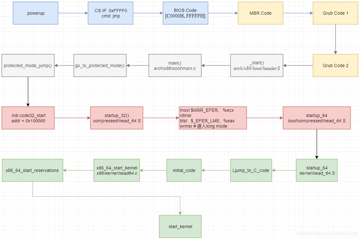
5大阶段:
1、上电执行BIOS code
略.
2、执行MBR及grub引导code
暂略.
3、real-mode code
实模式下是20位地址寻址,的寻址方式是segment:offset。首先要配置好实模式运行环境,主要就是配制好各个段寄存器、栈、堆等。
该部分代码在header.S/main.c/pm.c/pmjump.S/head_64.S等文件:
3.1 header.S文件结构
从结构上主要分为3各部分:
1)从“MZ”后开始——到“boot_flag: .word 0xaa55”
这部分为Linux自带的bootloader,目前已经不再使用。功能相当于启动硬盘第一个扇区的MBR。其中从".globl hdr"到该部分结束区域为"hdr"结构的上半部分。"hdr"结构类型对应的是"struct setup_header hdr;"
2)从“boot_flag: .word 0xaa55”后开始——到“start_of_setup:”之前
存放了系统启动参数结构"hdr"的后半部分。
3)剩余部分
实模式运行环境配置的代码。主要就是设置了各个段基址、栈。
3.2 header.S执行逻辑
在将控制权交给kernel之前,grub设置了各个段寄存器的基址,均指向的是该文件“.bstext”段基址,其值为“0x1000”,其中cs段则指向了1020,根据实际地址 = cs << 4 + offset,得到可执行code的地址为10200,也就是“.bstext”偏移512字节的位置,刚好就是该文件的_start位置处。
_start:
		.byte	0xeb                 # 0xeb在opcode中查询出是短跳转指令
		.byte	start_of_setup-1f    # 跳转距离是start_of_setup-1f
1:
        ……
start_of_setup:
        ……
该位置放的刚好是个跳转指令,即跳转到start_of_setup位置继续执行。这部分code的主要功能:
# 1.将所有段寄存器的值设置成一样的内容
# 2.设置堆栈
# 3.设置 bss (静态变量区)
# 4.跳转到 main.c 开始执行代码
3.3 main.c
解释如下:
void main(void)
{
	/* First, copy the boot header into the "zeropage" */
	copy_boot_params();/*拷贝header.S中定义的hdr结构信息到zeropage
	其中拷贝了32位系统的入口地址 code32_start: 0x100000 */

	/* Initialize the early-boot console */
	console_init();
	if (cmdline_find_option_bool("debug"))
		puts("early console in setup code\n");

	/* End of heap check */
	init_heap();//堆初始化

	/* Make sure we have all the proper CPU support */
	if (validate_cpu()) {//验证CPU
	/* 做了大量的其他检测和设置工作
	1)检查cpu标志,如果cpu是64位cpu,那么就设置long mode,
	2) 检查CPU的制造商,根据制造商的不同,打对应的补丁
	*/
		puts("Unable to boot - please use a kernel appropriate "
		     "for your CPU.\n");
		die();
	}

	/* Tell the BIOS what CPU mode we intend to run in. */
	set_bios_mode();//利用15号中断,告诉BIOS Linux是否要进入long mode

	/* Detect memory layout */
	detect_memory();/* 内存分布侦测,结果放入boot_params.e820_table */

	/* Set keyboard repeat rate (why?) and query the lock flags */
	keyboard_init();//键盘初始化

	/* Query Intel SpeedStep (IST) information */
	query_ist();

	/* Query APM information */
#if defined(CONFIG_APM) || defined(CONFIG_APM_MODULE)
	query_apm_bios();/* 从BIOS获得 高级电源管理 信息 */
#endif

	/* Query EDD information */
#if defined(CONFIG_EDD) || defined(CONFIG_EDD_MODULE)
	query_edd();/*从BIOS中查询 Enhanced Disk Drive 信息*/
#endif

	/* Set the video mode */
	set_video();/* 显示模式初始化 */

	/* Do the last things and invoke protected mode */
	go_to_protected_mode();/* 切换到保护模式 */
}
3.4 go_to_protected_mode
主要就是准备好32位保护模式所需的环境。32位下的寻址方式,可以分段也可以分页,如果系统目标状态是32位,需要完成页表的划分,但我们这里的目标系统是64位,该阶段做好分段配置即可。
void go_to_protected_mode(void)
{
	/* Hook before leaving real mode, also disables interrupts */
	realmode_switch_hook();/* realmode_swtch 还未设置,所以走else*/

	/* Enable the A20 gate */
	if (enable_a20()) {//使能A20地址线
		puts("A20 gate not responding, unable to boot...\n");
		die();
	}

	/* Reset coprocessor (IGNNE#) */
	reset_coprocessor();/* 通过将 0 写入 I/O 端口 0xf0 和 0xf1
	以复位数字协处理器 */

	/* Mask all interrupts in the PIC */
	mask_all_interrupts();/* 屏蔽了从中断控制器
	和主中断控制器上除IRQ2以外的所有中断
	实际上就是屏蔽了全部pic中断*/

	/* Actual transition to protected mode... */
	setup_idt();//这里可以理解为,做了清除操作
	setup_gdt();//将gdt值写入GDTR寄存器
	protected_mode_jump(boot_params.hdr.code32_start,/* 保护模式代码入口       地址*/
			    (u32)&boot_params + (ds() << 4));/*这个参数为boot_params
			    在实模式下的实际物理地址 段基址偏移4bit(ds << 4) + 偏移地址(&boot_params)

			    函数定义在 ./arch/x86/boot/pmjump.S:
			    主要功能是:在执行code32_start开始的code之前,
			    准备好保护模式所需的32位环境
			    */

}
相较于实模式,除了地址位数的增加,保护模式还增加采用了idtr、gdtr、ldtr等寄存器,因此首先进行初始设置,32位保护模式的段基址,是从gdtr中获取,ds/cs/ss等存放的是对应段描述符结构在gdtr中的索引。
protected_mode_jump对应的汇编代码部分即做了这部分初始化工作:
GLOBAL(protected_mode_jump)
	movl	%edx, %esi		# Pointer to boot_params table

	xorl	%ebx, %ebx		# 清除ebx寄存器
	movw	%cs, %bx
	shll	$4, %ebx		# 左移4位
	addl	%ebx, 2f		# 将标号为2的代码物理地址放入 ebx
	jmp	1f			# Short jump to serialize on 386/486
1:

	movw	$__BOOT_DS, %cx		# 暂存DS和TSS的索引 3 * 8 = 24,字节大小的索引
	movw	$__BOOT_TSS, %di	# 参见 segment.h, 所以此处值为 4 * 8 = 32

	movl	%cr0, %edx		# 修改利用dl修改edx的低位
	orb	$X86_CR0_PE, %dl	# Protected mode X86_CR0_PE定义在 processor-flags.h
	movl	%edx, %cr0		# 置CR0 的bit0,启用保护模式

	# Transition to 32-bit mode
	.byte	0x66, 0xea		# ljmpl opcode /* 0x66 操作符前缀
					#  允许我们混合执行 16 位和 32 位代码
					#  0xea 为跳转指令的操作符 */
2:	.long	in_pm32			# 跳转地址偏移为 in_pm32
	.word	__BOOT_CS		# segment 2 * 8 = 16, cs的指向索引值为16
# 至此,各个寄存器暂存值为:
#	esi: boot_params
#	ebx: 标号为2的代码物理地址
#	 cx: $__BOOT_DS
#	 di: $__BOOT_TSS
#	 dx: cr0
#	然后执行in_pm32代码

ENDPROC(protected_mode_jump)

	.code32				# 以下code属于.code32段。注意:
					# 但这里并不是code32段的起始部分
	.section ".text32","ax"
GLOBAL(in_pm32)
	# Set up data segments for flat 32-bit mode 重置CS之外的所有段指向$__BOOT_DS = 24
	movl	%ecx, %ds
	movl	%ecx, %es
	movl	%ecx, %fs
	movl	%ecx, %gs
	movl	%ecx, %ss
	# The 32-bit code sets up its own stack, but this way we do have
	# a valid stack if some debugging hack wants to use it.
	# 32位的代码设置自己栈,但是这种方式下,
	# 如果某调试黑客要使用它,我们需要一个有效的栈
	# 所以? 标号2的地址再加上ESP 扩展栈指针寄存器
	addl	%ebx, %esp

	# Set up TR to make Intel VT happy
	ltr	%di			# 将TSS装入ltr寄存器

	# Clear registers to allow for future extensions to the
	# 32-bit boot protocol 清如下所有寄存器
	xorl	%ecx, %ecx
	xorl	%edx, %edx
	xorl	%ebx, %ebx
	xorl	%ebp, %ebp
	xorl	%edi, %edi

	# Set up LDTR to make Intel VT happy
	lldt	%cx			# 将数据段装入ldt寄存器

	jmpl	*%eax			# Jump to the 32-bit
	# entrypoint 跳到参数传入的地址执行,短跳转,说明还是当前段
之后便执行传入的code32_start指向位置处的code,即保护模式代码。
code32_start地址指向的为head_64.S中的startup_32函数,由__HEAD标识。
4、protected mode
4.1 startup_32
这部分code首先是重新设置了ds/es/ss,之所需要重新来一遍,是因为有的引导程序可能跳过了前面的realmode代码,直接执行startup_32这部分。
ENTRY(startup_32)

	cld	# 清 FLAGS 寄存器的 DF 位

	testb $KEEP_SEGMENTS, BP_loadflags(%esi)# ESI是Pointer to boot_params table
	jnz 1f 				        # 没有设置,继续往下走

	cli
	movl	$(__BOOT_DS), %eax	        # 设置各个段寄存器描述符索引为 ds = 24
	movl	%eax, %ds		        # 这部分在 in_pm32 函数中已经设置过
	movl	%eax, %es		        # 之所以这么做,因为有的引导协议跳过in_pm32直接到了这里
	movl	%eax, %ss
紧接着,是重新计算当前code所处的实际位置。之所以需要重新计算,是因为在编译这部分代码时,编译器将这部分重新编址了,而不是紧接着0x100000来的。然后就是更新栈底的物理地址到esp。
1:

	leal	(BP_scratch+4)(%esi), %esp	# 把 scratch 的地址加 4 存入 esp 栈指针寄存器
						# 将成为一个临时的栈

	call	1f				# 跳到1f,此时栈中放的就是1f返回地址
						# 返回地址是实际物理地址

1:	popl	%ebp				# 把栈中的1f的实际物理地址放到刚才的临时栈
	subl	$1b, %ebp			# 用该地址减去1f的偏移地址,得到0地址的实际物理地址

# setup a stack and make sure cpu supports long mode.
	movl	$boot_stack_end, %eax
	addl	%ebp, %eax
	movl	%eax, %esp			# 计算boot_stack_end实际物理地址, 放入esp
问题来了,为撒要重新编址呢……?
接下来,在判断完cpu是否支持long mode之后,又是一段获取“Target address to relocate to for decompression ”。 这个地址之所以不固定,却是计算得出,原因在于编译期间采用了-fPIC参数,得到的内核镜像是位置无关的代码,即,代码位置 = 控制地址 + 程序计数器。
	call	verify_cpu			# 需要检查 CPU 是否支持 长模式 和 SSE
	testl	%eax, %eax
	jnz	no_longmode			# 不支持的话,跳转到no_longmode,然后停机
						# 支持的话,往下继续分析

#ifdef CONFIG_RELOCATABLE			# 这个配置用于kdump,救援内核
	movl	%ebp, %ebx
	movl	BP_kernel_alignment(%esi), %eax	# 2M地址对齐boot_params
	decl	%eax
	addl	%eax, %ebx
	notl	%eax
	andl	%eax, %ebx
	cmpl	$LOAD_PHYSICAL_ADDR, %ebx
	jge	1f				# 如果配置大于等于,就用配置的
#endif
	movl	$LOAD_PHYSICAL_ADDR, %ebx	# 否则还是用配置的
1:

	/* Target address to relocate to for decompression */
	movl	BP_init_size(%esi), %eax	# 获取 init 全部大小
	subl	$_end, %eax			# 减去本.code32段大小
	addl	%eax, %ebx			# 计算得到剩余 init 的实际位置
至此,ebp 包含了bootloader加载后的code32段物理地址,ebx存放可安全进行解压缩内核镜像的地址。
再接着就是准备64位的环境了,包括设置CR4的PAE,构建早期4G启动页表等。
	addl	%ebp, gdt+2(%ebp)		# ebp 加上 gdt 偏移2的位置
						# 查看 gdt 的定义可见,偏移后指向的
						# 就是 gdt 的偏移地址,加上ebp就得到
						# gdt的实际物理地址base,并装入gdt.gdt
	lgdt	gdt(%ebp)			# 这样得到48位的GDTR:limit:base
						# 即gdt.(gdt_end - gdt): gdt.gdt

	/* Enable PAE mode */
	movl	%cr4, %eax
	orl	$X86_CR4_PAE, %eax
	movl	%eax, %cr4			# 设置CR4的bit5 PAE

 /*
  * Build early 4G boot pagetable		# 构建早期4G启动页表
  *	# Linux 内核使用 4级 页表,通常我们会建立6个页表
  *	# 分别为1个PML4, 1个PDP, 4个PDT
  */
	/*
	 * If SEV is active then set the encryption mask in the page tables.
	 * This will insure that when the kernel is copied and decompressed
	 * it will be done so encrypted.
	 */
	call	get_sev_encryption_bit		# 跳到 mem_encrypt.S :21
	xorl	%edx, %edx
	testl	%eax, %eax
	jz	1f
	subl	$32, %eax	/* Encryption bit is always above bit 31 */
	bts	%eax, %edx	/* Set encryption mask for page tables */
				/* 为页表设置加密掩码 */
1:

	/* Initialize Page tables to 0 */	# 清理出一块缓存
	leal	pgtable(%ebx), %edi		# pgtable 的地址放到 edi 寄存器
	xorl	%eax, %eax			# 清 eax 寄存器
	movl	$(BOOT_INIT_PGT_SIZE/4), %ecx	# 在 ecx 中放入(4096 * 6 / 4 = 6144)
						# 共有6个页表,每个页表1页(4k=4096)
						# 每次清4byte,所以清6144次
	rep	stosl				# 重复把 eax 的值写入 edi 指向的位置(即清零)
						# 每次4个字节,直到ecx减小到0

	/* Build Level 4 */
	leal	pgtable + 0(%ebx), %edi		# 顶级页表地址放入edi
	leal	0x1007 (%edi), %eax		# 该值 0x1000 | 0x007, 放的是下级 PDE 的属性
						# 7代表了 PML4 的项标记, 0x1000代表大小
	movl	%eax, 0(%edi)			# 将下级PDE属性位置放入本表的0地址处
	addl	%edx, 4(%edi)			# 在偏移位置4放入加密掩码

	/* Build Level 3 */
	leal	pgtable + 0x1000(%ebx), %edi	# 3级页表暂放edi
	leal	0x1007(%edi), %eax		# 同上,下级 PTE 0 属性的位置
	movl	$4, %ecx			# 放入值为4,循环次数,说明后面支持4个PDT
1:	movl	%eax, 0x00(%edi)		# 同上
	addl	%edx, 0x04(%edi)		# 同上
	addl	$0x00001000, %eax		# 每次偏移1 page
	addl	$8, %edi			# 每个 PTE 的信息8个字节,因此下个位置增加8
	decl	%ecx				# 自减
	jnz	1b				# 跳至前标号1处循环

	/* Build Level 2 */
	leal	pgtable + 0x2000(%ebx), %edi
	movl	$0x00000183, %eax		# 初始化下级 page 的属性值为0x183
	movl	$2048, %ecx			# 同上,说明后面支持2048个 PAGE
1:	movl	%eax, 0(%edi)			# 将页属性183放在 PTE 首地址
						# 第一次放位置0
	addl	%edx, 4(%edi)			# 同上
	addl	$0x00200000, %eax		# 后续每次偏移2M
	addl	$8, %edi			# 每个 PAGE 的信息8个字节,这一轮下来,刚好4页
	decl	%ecx				# ecx 自减1
	jnz	1b				# 这样将循环2048次

	/* Enable the boot page tables */
	leal	pgtable(%ebx), %eax
	movl	%eax, %cr3			# 将高级页表项PML4的地址放入CR3
再往下就是利用MSR enable long mode、load ltr、设置CR0的PG/PE,然后调用startup_64函数,进入long mode的处理了。
	leal	startup_64(%ebp), %eax		# 将 startup_64 的地址导入 eax
#ifdef CONFIG_EFI_MIXED
	movl	efi32_config(%ebp), %ebx
	cmp	$0, %ebx
	jz	1f
	leal	handover_entry(%ebp), %eax
1:
#endif
	pushl	%eax				# 将 startup_64 的地址入栈

	/* Enter paged protected Mode, activating Long Mode */
	movl	$(X86_CR0_PG | X86_CR0_PE), %eax /* Enable Paging and Protected mode */
	movl	%eax, %cr0			# 使能保护模式分页

	/* Jump from 32bit compatibility mode into 64bit mode. */
	lret					# 取出栈地址 startup_64 并跳转到那里执行
5、long mode(IA-32e/64)
5.1 compressed/header_64.S:startup_64
开始依旧是设置重置cs之外的各个段寄存器,重新计算可安全进行解压缩内核镜像的地址。既然都要重复计算,为什么还要在保护模式下先计算一遍……下面关于5级分页的,暂不管,来到这段代码:
	pushq	%rsi
	leaq	(_bss-8)(%rip), %rsi
	leaq	(_bss-8)(%rbx), %rdi
	movq	$_bss /* - $startup_32 */, %rcx
	shrq	$3, %rcx
	std
	rep	movsq
	cld
	popq	%rsi


 361
361

 被折叠的 条评论
为什么被折叠?
被折叠的 条评论
为什么被折叠?
 到【灌水乐园】发言


