


前言:
本文引入了iic、SMbus传输数据的原理,讲解了基于SMBus协议的API调用,包含i2c-tools编译后的库文件建立工程at24c02_test,进行了基于IMX6ull板子和AT24C02存储器的数据传输实验
- iic应用场景:加密芯片,触摸屏
1.原理框架
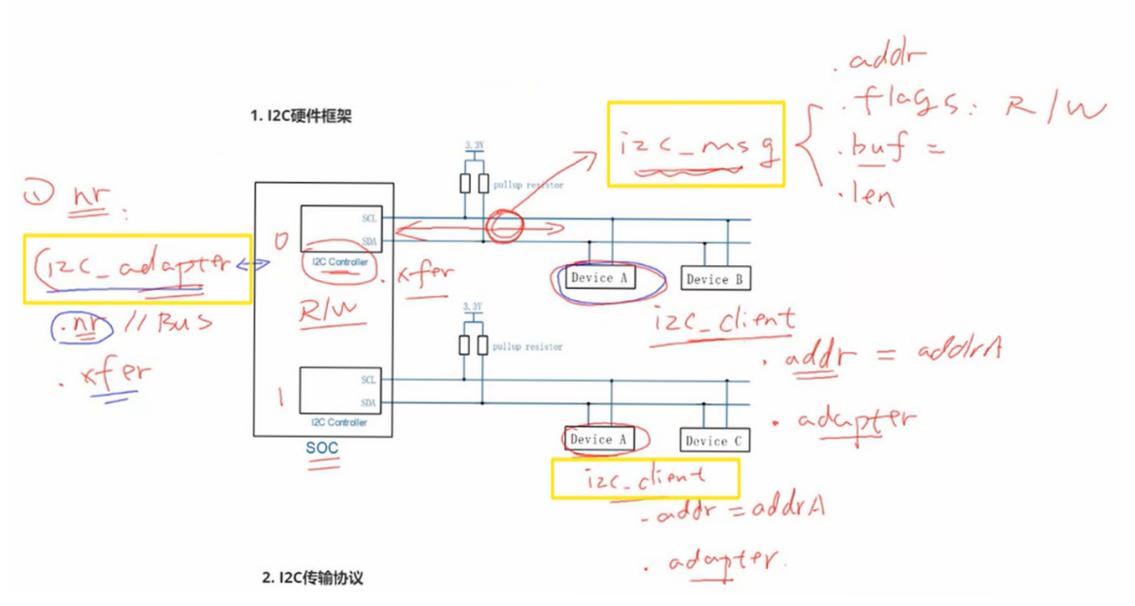
*1.1 iic硬件连接 *
| 主设备:Soc,从设备:Device A… |
|---|
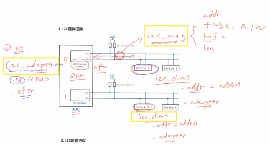
- iic controller 和 iic device 建立通信
- 用户要确定使用哪条iic总线,即nr
- iic controller端使用i2c_adapter结构体,里面有.xfer()函数发送数据,有nr变量
- iic device端使用i2c.client结构体,里面有设备addr变量,有记录设备挂载在哪个iic controller的.adapter变量(实际上addr变量是在i2c_adapter结构体里记录)
- iic controller端和iic device端之间是iic_msg结构体,其为传输的数据,含有flag标记为写/读,有buf[]、len变量记录数据和长度
int i2c_transfer(struct i2c_adapter *adap, struct i2c_msg *msgs, int num)
| .xfer函数 |
|---|
怎么表示要传输的数据呢?
u8 data_addr = 0x10;
i8 data;
struct i2c_msg msgs[2];
msgs[0].addr   = 0x50;
msgs[0].flags  = 0;
msgs[0].len
= 1;
msgs[0].buf
= &data_addr;
msgs[1].addr   = 0x50;
msgs[1].flags  = I2C_M_RD;
msgs[1].len
= 1;
msgs[1].buf
= &data;
| msg[0]对0x50设备发送“写”命令,msg[1]读取 从设备的0x10地址的数据 |
|---|
1.2 iic写操作
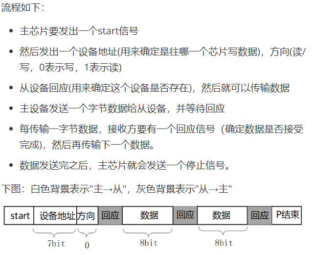
1.3 iic读操作
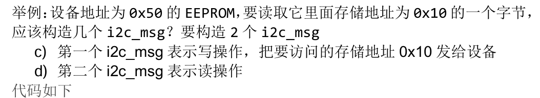
1.4 iic数据传输格式:
9个时钟内,发送8位数据地址(7位地址、1位表读或写,0为写,1为读)、1位反馈位。(SCL为低电平时,从设备读取SDA;SCL为高时候,SDA信号可以变化,具体变1还是0由8位地址决定。1位反馈位,主设备默认为低电平不驱动三极管,从设备反馈时驱动三极管拉低SDA,原因看SDA的真值表,无反馈则SDA为高电平)
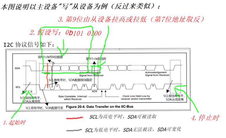
| 图中第3点写错了,第9个clk的SDA初始为高,从设备反馈时拉低,否则为高(第9个clk时候主设备不驱动三极管,主设备out端为0,从设备不驱动时out为0,SDA由上拉电阻控制为高电平;从设备驱动时out为1,SDA被拉低为0) |
|---|
1.5 iic中主、从设备怎么控制SDA信号,实现分时控制iic总线?
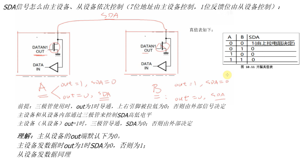
| 主从设备分时控制iic总线图,SDA真值表 |
|---|
1.6 比起iic通信,更常用的兼容iic协议的是SMBus协议,主要区别是SMBus明确了数据传输格式,且在写、读之间,可以不发出P信号,而是直接发出S信号
1.7 SMBus中的symbols
S     (1 bit) : Start bit(开始位)
Sr    (1 bit) : 重复的开始位
P     (1 bit) : Stop bit(停止位)
R/W#  (1 bit) : Read/Write bit. Rd equals 1, Wr equals 0.(读写位)
A, N  (1 bit) : Accept and reverse accept bit.(回应位)
Address(7 bits): I2C 7 bit address. Note that this can be expanded as usual to
                get a 10 bit I2C address.
                (地址位,7位地址)
Command Code  (8 bits): Command byte, a data byte which often selects a register on
                the device.
                (命令字节,一般用来选择芯片内部的寄存器)
Data Byte (8 bits): A plain data byte. Sometimes, I write DataLow, DataHigh
                for 16 bit data.
                (数据字节,8位;如果是16位数据的话,用2个字节来表示:DataLow、DataHigh)
Count (8 bits): A data byte containing the length of a block operation.
				(在block操作总,表示数据长度)
[..]:           Data sent by I2C device, as opposed to data sent by the host
                adapter.
                (中括号表示I2C设备发送的数据,没有中括号表示host adapter发送的数据)
``
1.8 SMBus的API
注意:R/W#本意是用来表示读或写,Command Code 表示从设备内寄存器地址
| type | CC/NCC-有无Command Code | 图示 |
|---|---|---|
| 2.2 SMBus Quick Command | NCC | 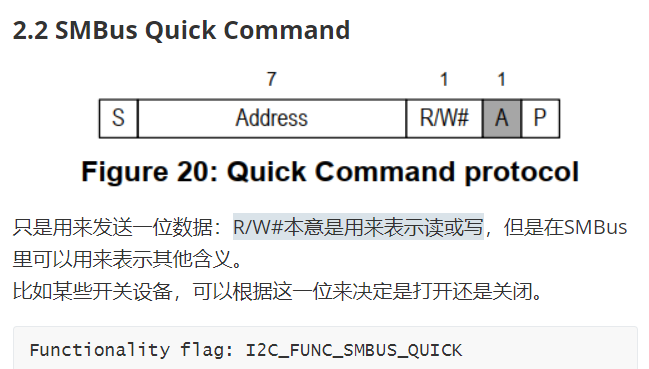 |
| 2.3 SMBus Receive Byte | NCC | 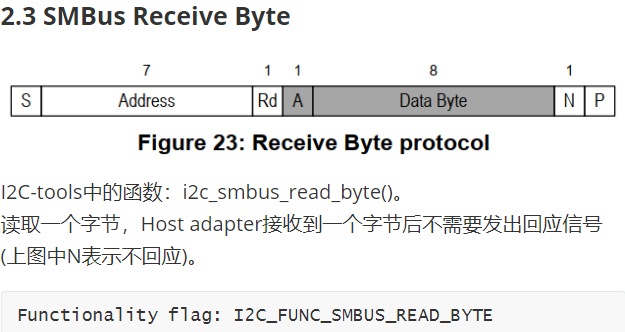 |
| 2.4 SMBus Send Byte | NCC | 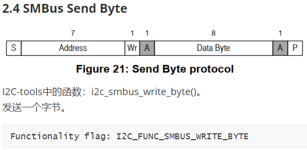 |
| 2.5 SMBus Read Byte | CC | 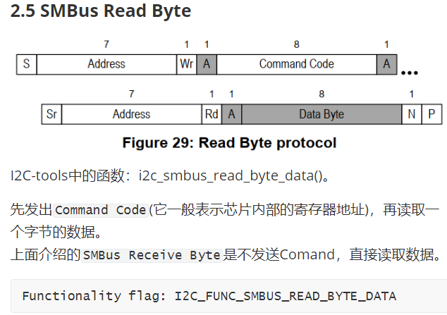 |
| 2.6 SMBus Read Word | CC | 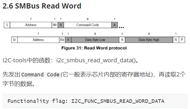 |
| 2.7 SMBus Write Byte | CC | 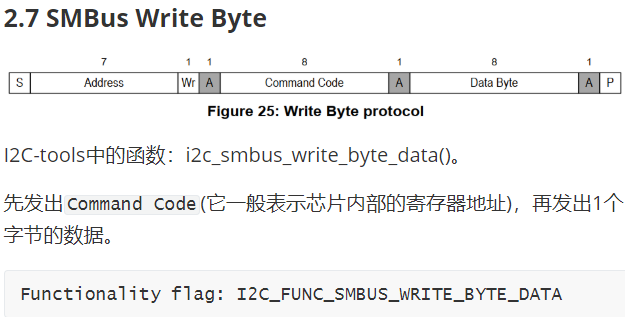 |
| 2.8 SMBus Write Word | CC | 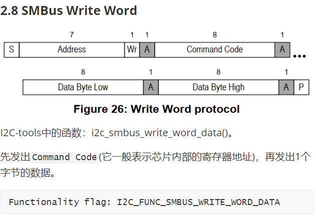 |
| 2.9 SMBus Block Read | CC | 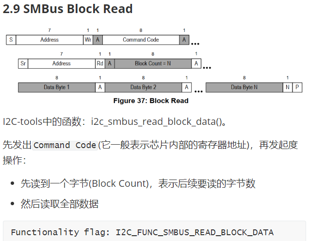 |
| 2.10 SMBus Block Write | CC | 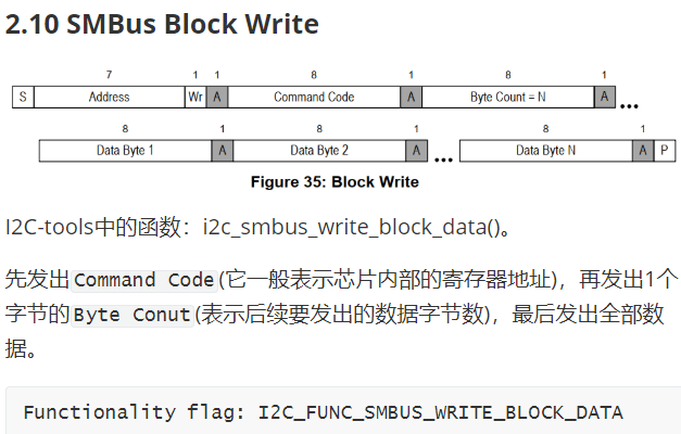 |
| 2.11 I2C Block Read | CC | 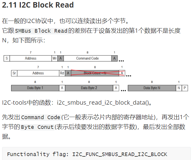 |
| 212 I2C Block Write | CC | 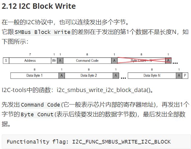 |
| 2.13 SMBus Block Write - Block Read Process Call | CC | 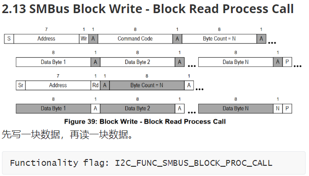 |
| 2.14 Packet Error Checking (PEC) | NCC | 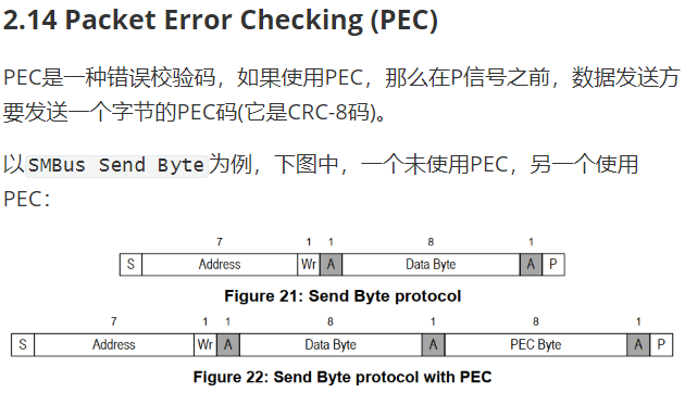 |
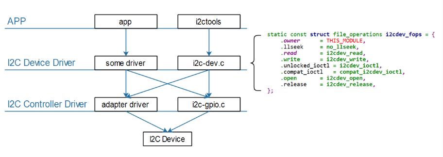
1.9 i2c-tools(需要下载,安装编译后移植libi2c.so文件到开发板)
应用层访问硬件肯定是需要驱动程序的。对于I2C设备,Linux内核已经提供驱动程序drivers/i2c/i2c-dev.c,通过它可以直接使用下面的I2C控制器驱动程序来访问I2C设备,而i2c-tools正是基于该驱动开发的一套示例代码,也是一套好用的调试工具。框架如下:
代码测试(在imx6ull上输入命令查看i2c设备信息):
// 列出当前的I2C Adapter(或称为I2C Bus、I2C Controller)
# i2cdetect -l
// --表示没有该地址对应的设备, UU表示有该设备并且它已经有驱动程序,
// 数值表示有该设备但是没有对应的设备驱动
# i2cdetect -y -a 0
// 以imx6ull上的AT24c02为例,使用SMbus协议在终端测试通信
// 0号iic总线,0x1e设备地址,0表写入,0x4表复位,0x3表使能
// 0xc为寄存器地址,w表示read word data
# i2cset -f -y 0 0x1e 0 0x4
# i2cset -f -y 0 0x1e 0 0x3
# i2cget -f -y 0 0x1e 0xc w
# i2cget -f -y 0 0x1e 0xe w
//使用使用I2C协议测试
# i2ctransfer -f -y 0 w2@0x1e 0 0x4
# i2ctransfer -f -y 0 w2@0x1e 0 0x3
# i2ctransfer -f -y 0 w1@0x1e 0xc r2
# i2ctransfer -f -y 0 w1@0x1e 0xe r2
2.源码分析
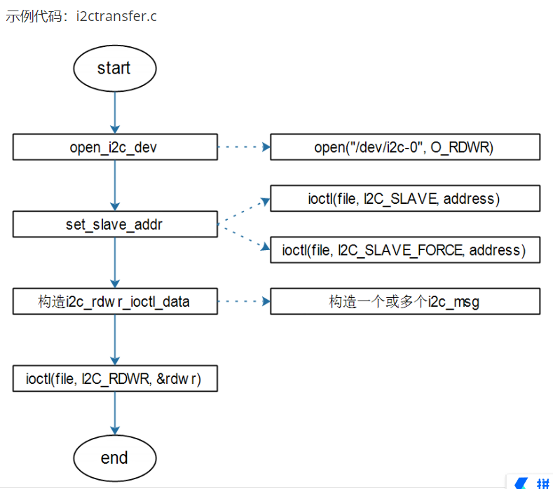
2.1 iic方式
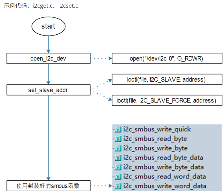
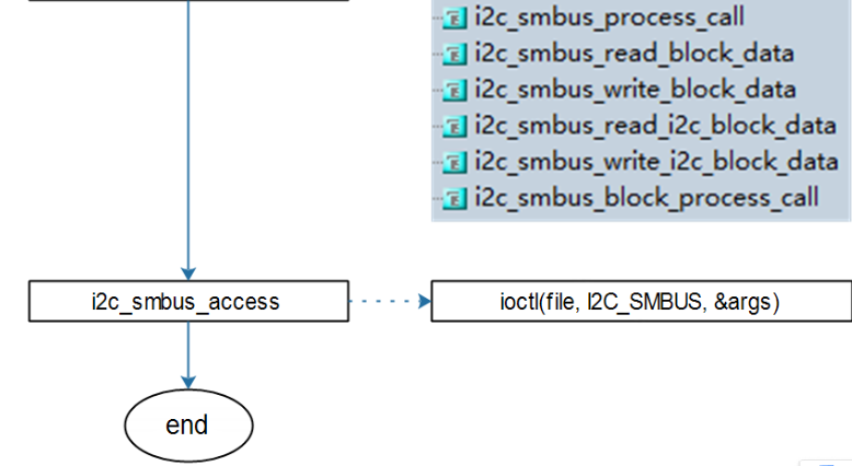
2.2 SMBus方式
3.SMBus方式测试通信实例
at24c02_test.c
#include <sys/ioctl.h>
#include <errno.h>
#include <string.h>
#include <stdio.h>
#include <stdlib.h>
#include <unistd.h>
#include <linux/i2c.h>
#include <linux/i2c-dev.h>
#include <i2c/smbus.h>
#include "i2cbusses.h"
#include <time.h>


/* ./at24c02 <i2c_bus_number> w "100ask.taobao.com"
 * ./at24c02 <i2c_bus_number> r
 */

int main(int argc, char **argv)
{
	unsigned char dev_addr = 0x50;
	unsigned char mem_addr = 0;
	unsigned char buf[32];

	int file;
	char filename[20];
	unsigned char *str;

	int ret;

	struct timespec req;

	if (argc != 3 && argc != 4)
	{
		printf("Usage:\n");
		printf("write eeprom: %s <i2c_bus_number> w string\n", argv[0]);
		printf("read  eeprom: %s <i2c_bus_number> r\n", argv[0]);
		return -1;
	}

	file = open_i2c_dev(argv[1][0]-'0', filename, sizeof(filename), 0);
	if (file < 0)
	{
		printf("can't open %s\n", filename);
		return -1;
	}

	if (set_slave_addr(file, dev_addr, 1))
	{
		printf("can't set_slave_addr\n");
		return -1;
	}

	if (argv[2][0] == 'w')
	{
		// write str: argv[3]
		str = argv[3];

		req.tv_sec  = 0;
		req.tv_nsec = 20000000; /* 20ms */

		while (*str)
		{
			// mem_addr, *str
			// mem_addr++, str++
			ret = i2c_smbus_write_byte_data(file, mem_addr, *str);
			if (ret)
			{
				printf("i2c_smbus_write_byte_data err\n");
				return -1;
			}
			// wait tWR(10ms)
			nanosleep(&req, NULL);

			mem_addr++;
			str++;
		}
		ret = i2c_smbus_write_byte_data(file, mem_addr, 0); // string end char
		if (ret)
		{
			printf("i2c_smbus_write_byte_data err\n");
			return -1;
		}
	}
	else
	{
		// read
		ret = i2c_smbus_read_i2c_block_data(file, mem_addr, sizeof(buf), buf);
		if (ret < 0)
		{
			printf("i2c_smbus_read_i2c_block_data err\n");
			return -1;
		}

		buf[31] = '\0';
		printf("get data: %s\n", buf);
	}

	return 0;

}
- 在i2c-tools编译下的目录里建立工程文件at24c02_test.c(因为要用到编译的lib文件等),然后建立一个makefile文件:
makefile文件:
all:
	$(CROSS_COMPILE)gcc -I ./include -o at24c02_test at24c02_test.c i2cbusses.c smbus.c
- 其中i2cbusses.c smbus.c为i2c-tools编译生成的库文件
- 将工程移植到ubuntu,输入交叉编译环境:
export ARCH=arm
export CROSS_COMPILE= arm-buildroot-linux-gnueabihf-
export PATH=$PATH:/home/book/100ask_imx6ull-sdk/ToolChain/arm-buildroot-linux-gnueab
 ihf_sdk-buildroot/bin
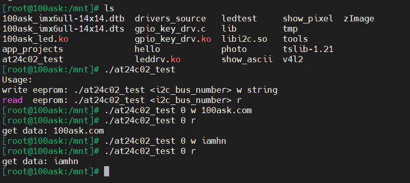
- 然后make,得到可执行文件,将可执行文件at24c02_test 移植到开发板上执行
- 最终结果:
参考资料:
- i2c-tools(csdn) : https://blog.youkuaiyun.com/weixin_53226223/article/details/135250445
- 韦东山应用开发资料(b站)
- ap3216c文件(百度)
总结:本文为个人学习iic通信时的总结,学的时候很糊涂,搞不清ap3216c写入0x3、0x4的原因,看不完全SCL和SDA硬件原理图,如今是初步掌握了用法。本文较为罗嗦,今后会简化原理方面,多注重代码层的讲解。
如果觉得有帮助的话,请点个赞吧!
感谢观看!


 1276
1276

 被折叠的 条评论
为什么被折叠?
被折叠的 条评论
为什么被折叠?
 到【灌水乐园】发言


