


 本文详细介绍了一个基于192.168.1.0/24的网络实验配置过程,包括IP地址合理划分、静态路由配置及避免环路的方法。通过具体步骤说明如何实现全网可达,以及如何通过浮动静态路由确保链路故障时仍能保持通信。
实验要求:
1.除R5的环回地址固定以外,整个其他所有网段基于192.168.1.0/24进行合理的IP地址划分;
2.R1-R4每个路由器存在两个环回接口,用于模拟连接Pc网段;地址也在192.168.1.0/24这个网络范围内;
3.R1-R4上不能直接编写到达5.5.5.0/24的静态路由,但依然可以访问;
4.全网可达,尽量减少每台路由器,路由表条目数量,避免环路出现;
5.R4与R5间,正常1000M链路通信,故障时自动改为100M。
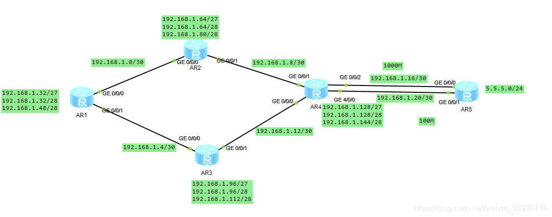
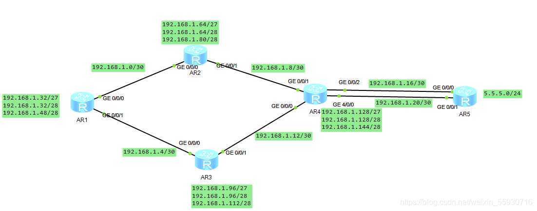
实验拓扑:
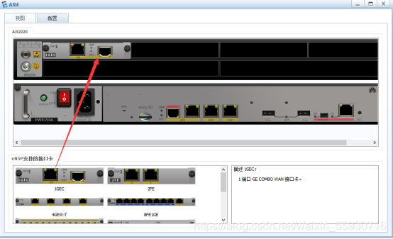
AR4如果没有可用端口右击—设置—添加板卡(直接托上去)如图:
实验分析:
IP地址根据题目要求使用192.168.1.0/24进行划分,划分时,考虑怎么划分才能做到不浪费,可以将IP地址分成以下几类:骨干链路IP地址和各个路由器上的环回接口地址;骨干中每个网段需要两个IP地址,因此可以使用30位的掩码。在该实验中需要5(用户网段)+1(骨干网段)个网段,在骨干网段中,直接使用30位网络位的IP地址,将其他剩余地址作为预留地址,以备之后的网络扩容使用。
子网划分:
192.168.1.0/24
192.168.1.000 000 00   192.168.1.0/27     -----骨干链路
   192.168.1.000 000 00   192.168.1.0/30
   192.168.1.000 001 00   192.168.1.4/30
   192.168.1.000 010 00   192.168.1.8/30
   192.168.1.000 011 00   192.168.1.12/30
   192.168.1.000 100 00   192.168.1.16/30
   192.168.1.000 101 00   192.168.1.20/30
   192.168.1.000 110 00  -----预留
   192.168.1.000 111 00  -----预留
192.168.1.001 0 0000    192.168.1.32/27    -----R1环回
   192.168.1.001 0 0000  192.168.1.32/28
   192.168.1.001 1 0000  192.168.1.48/28
192.168.1.010 0 0000  192.168.1.48/28      -----R2环回
   192.168.1.010 0 0000   192.168.1.64/28
   192.168.1.010 1 0000   192.168.1.80/28
192.168.1.011 00000  192.168.1.96/27       ----R3环回
   192.168.1.011 0 0000  192.168.1.96/28
   192.168.1.011 1 0000  192.168.1.112/28
192.168.1.100 00000  192.168.1.128/27      -----R4环回
   192.168.1.100 0 0000  192.168.1.128/28
   192.168.1.100 1 0000  192.168.1.144/28
192.168.1.101 00000  192.168.1.160/27  -----预留
192.168.1.110 00000  192.168.1.192/27  -----预留
192.168.1.111 00000  192.168.1.144/27  -----预留
最终IP地址分配如图:
实验配置:
首先按照地址划分配置IP地址,并在配置时验证IP地址准确性;
先将5个路由器名称分别改为R1,R2,R3,R4,R5.
<Huawei>system-view
[Huawei]sys R1
[R1]
同理改R2-R5
R1的静态路由配置
[R1]int g 0/0/0
[R1-GigabitEthernet0/0/0]ip add 192.168.1.1 30
[R1-GigabitEthernet0/0/0]int g 0/0/1
[R1-GigabitEthernet0/0/1]ip add 192.168.1.5 30
[R1-GigabitEthernet0/0/1]int l0
[R1-LoopBack0]ip add 192.168.1.33 28
[R1-LoopBack0]int l1
[R1-LoopBack1]ip add 192.168.1.49 28
R2的静态路由配置
[R2]int g 0/0/0
[R2-GigabitEthernet0/0/0]ip add 192.168.1.2 30
[R2-GigabitEthernet0/0/0]int g 0/0/1
[R2-GigabitEthernet0/0/1]ip add 192.168.1.9 30
[R2-GigabitEthernet0/0/1]int l0
[R2-LoopBack0]ip add 92.168.1.65 28
[R2-LoopBack0]int l1
[R2-LoopBack1]ip add 92.168.1.81 28
R3的静态路由配置
[R3]int g 0/0/0
[R3-GigabitEthernet0/0/0]ip add 192.168.1.6 30
[R3-GigabitEthernet0/0/0]int g 0/0/1
[R3-GigabitEthernet0/0/1]ip add 192.168.1.13 30
[R3-GigabitEthernet0/0/1]int l0
[R3-LoopBack0]ip add 192.168.1.97 28
[R3-LoopBack0]int l1
[R3-LoopBack1]ip add 192.168.1.113 28
R4的静态路由配置
[R4]int g 0/0/0
[R4-GigabitEthernet0/0/0]ip add 192.168.1.14 30
[R4-GigabitEthernet0/0/0]int g 0/0/1
[R4-GigabitEthernet0/0/1]ip add 192.168.1.10 30
[R4-GigabitEthernet0/0/1]int l0
[R4-LoopBack0]ip add 192.168.1.129 28
[R4-LoopBack0]int l1
[R4-LoopBack1]ip add 192.168.1.145 28
[R4-LoopBack1]int g 0/0/2
[R4-GigabitEthernet0/0/2]ip add 192.168.1.17 30
[R4-GigabitEthernet0/0/2]int g 4/0/0
[R4-GigabitEthernet4/0/0]ip add 192.168.1.21 30
R5的静态路由配置
[R5]int g 0/0/0
[R5-GigabitEthernet0/0/0]ip add 192.168.1.18 30
[R5-GigabitEthernet0/0/0]int g 0/0/1
[R5-GigabitEthernet0/0/1]ip add 192.168.1.22 30
[R5-GigabitEthernet0/0/1]int l0
[R5-LoopBack0]ip add 5.5.5.5 24
注:这种大量的IP还是要检查一下,不然后面会很麻烦的。
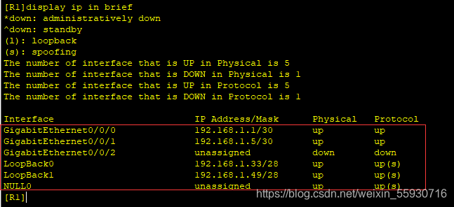
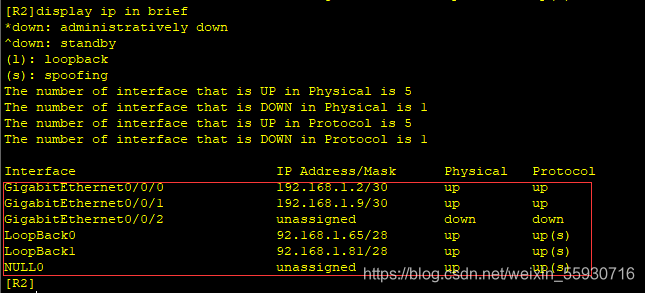
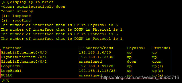
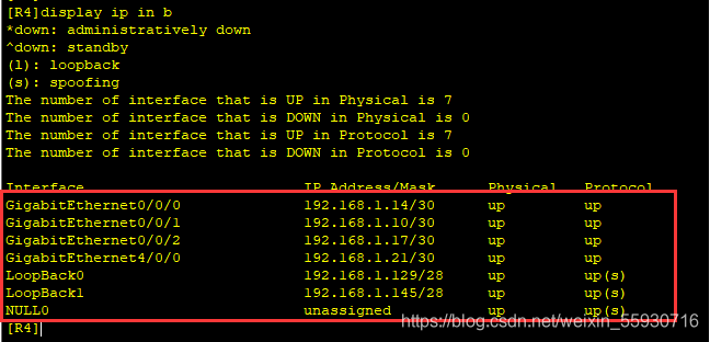
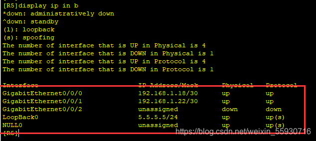
查看IP地址是否配置齐全
display ip in brief (display ip interface brief 这是全拼)
R1的IP配置查看:
R2的IP配置查看:
R3的IP配置查看:
R4的IP配置查看:
R5的IP配置查看:
要实现全网可达则接下来配置路由(简单是简单的,就是工作量有点大,所以按顺序配,不然出错太麻烦了)
R1路由配置:
[R1]ip route-static 192.168.1.64 27 192.168.1.2
[R1]ip route-static 192.168.1.8 30 192.168.1.2
[R1]ip route-static 192.168.1.128 27 192.168.1.2
[R1]ip route-static 192.168.1.128 27 192.168.1.6
[R1]ip route-static 192.168.1.16 30 192.168.1.6
[R1]ip route-static 192.168.1.16 30 192.168.1.2
[R1]ip route-static 192.168.1.12 30 192.168.1.6
[R1]ip route-static 192.168.1.96 27 192.168.1.6
R2路由配置:
[R2]ip route-static 192.168.1.128 27 192.168.1.10
[R2]ip route-static 192.168.1.16 30 192.168.1.10
[R2]ip route-static 192.168.1.12 30 192.168.1.10
[R2]ip route-static 192.168.1.96 27 192.168.1.10
[R2]ip route-static 192.168.1.96 27 192.168.1.1
[R2]ip route-static 192.168.1.4 30 192.168.1.1
[R2]ip route-static 192.168.1.32 27 192.168.1.1
R3路由配置:
[R3]ip route-static 192.168.1.32 27 192.168.1.5
[R3]ip route-static 192.168.1.0 30 192.168.1.5
[R3]ip route-static 192.168.1.64 27 192.168.1.5
[R3]ip route-static 192.168.1.64 27 192.168.1.14
[R3]ip route-static 192.168.1.8 30 192.168.1.14
[R3]ip route-static 192.168.1.128 27 192.168.1.14
[R3]ip route-static 192.168.1.16 30 192.168.1.14
R4路由配置:
[R4]ip route-static 192.168.1.96 27 192.168.1.13
[R4]ip route-static 192.168.1.4 30 192.168.1.13
[R4]ip route-static 192.168.1.32 27 192.168.1.13
[R4]ip route-static 192.168.1.32 27 192.168.1.9
[R4]ip route-static 192.168.1.0 30 192.168.1.9
[R4]ip route-static 192.168.1.64 27 192.168.1.9
R5路由配置:
[R5]ip route-static 192.168.1.128 27 192.168.1.17
[R5]ip route-static 192.168.1.12 30 192.168.1.17
[R5]ip route-static 192.168.1.96 27 192.168.1.17
[R5]ip route-static 192.168.1.4 30 192.168.1.17
[R5]ip route-static 192.168.1.32 27 192.168.1.17
[R5]ip route-static 192.168.1.0 30 192.168.1.17
[R5]ip route-static 192.168.1.64 27 192.168.1.17
[R5]ip route-static 192.168.1.8 30 192.168.1.17
写完之后在几个路由上相互ping一下看是否能连通!
ping 直接跟IP
R1-R4上不能直接编写到达5.5.5.0/24的静态路由,目前还不能访问(也就是说ping 5.5.5.5 的话是ping不通的),要使其可以访问,因此开始给路由写缺省地址:
R1的缺省地址:
[R1]ip route-static 0.0.0.0 0 192.168.1.2
[R1]ip route-static 0.0.0.0 0 192.168.1.6
R2的缺省地址:
[R2]ip route-static 0.0.0.0 0 192.168.1.10
R3的缺省地址:
[R3]ip route-static 0.0.0.0 0 192.168.1.14
R4的缺省地址:
[R4]ip route-static 0.0.0.0 0 192.168.1.18
这个时候在R1-R4上分别ping5.5.5.5就能ping通啦!
避免环路出现,意味着在每个路由上添加环路空接口路由
R1:
[R1]ip route-static 192.168.1.32 27 NULL 0
R2:
[R2]ip route-static 192.168.1.64 27 NULL 0
R3:
[R3]ip route-static 192.168.1.96 27 NULL 0
R4:
[R4]ip route-static 192.168.1.128 27 NULL 0
R4与R5正常通过1000M链路,故障时通过100M链路;该要求可以使用浮动静态路由解决,将100M链路的优先级调整为61即可。
R5上要配回包路由
查看R5的路由
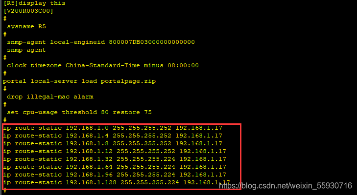
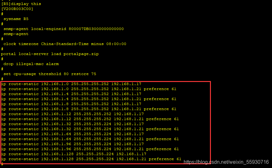
修改优先级
[R5]ip route-static 192.168.1.0 255.255.255.252 192.168.1.21 preference 61
[R5]ip route-static 192.168.1.4 255.255.255.252 192.168.1.21 preference 61
[R5]ip route-static 192.168.1.8 255.255.255.252 192.168.1.21 preference 61
[R5]ip route-static 192.168.1.12 255.255.255.252 192.168.1.21 preference 61
[R5]ip route-static 192.168.1.32 255.255.255.224 192.168.1.21 preference 61
[R5]ip route-static 192.168.1.64 255.255.255.224 192.168.1.21 preference 61
[R5]ip route-static 192.168.1.96 255.255.255.224 192.168.1.21 preference 61
[R5]ip route-static 192.168.1.128 255.255.255.224 192.168.1.21 preference 61
在R4-R5上的1000M的接口给断开
[R4] int g 0/0/2
[R4-GigabitEthernet0/0/2]shutdown
[R5]int g 0/0/0
[R5-GigabitEthernet0/0/0]shutdown
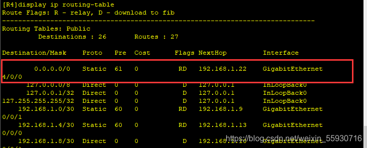
在R4上查看路由发现100M的接口已经浮上来了
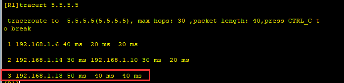
在R1上ping 5.5.5.5还能ping通,这是追踪一下路径(R2-R4也是一样的噢)
[R1]tracert 5.5.5.5
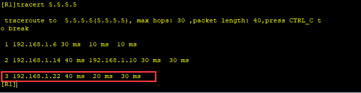
这是就走的是下面100M的接口。
实验在这就全部结束啦!
我们再让1000M接口连通做一下对比,看看有什么不同
当1000M接口连通时,会发现ping 5.5.5.5时走的就是1000M接口的线路。
实验总结:
每个路由器上的环回都做过子网汇总,因此需要添加空接口路由来避免路由黑洞。


 406
406

 被折叠的 条评论
为什么被折叠?
被折叠的 条评论
为什么被折叠?
 到【灌水乐园】发言


