


基于Matlab设计生成HDL/Verilog代码
本示例展示了如何创建HDL Coder项目并从MATLAB设计中生成代码。在这个例子中,你需要:
1、创建一个MATLAB HDL Coder项目。
2、将设计和测试台文件添加到项目中。
3、启动HDL Workflow Advisor进行MATLAB设计。
4、执行定点转换和生成HDL代码。
一、Matlab设计FIR滤波器
MATLAB设计的mlhdlc_sfir是一个简单的对称FIR滤波器。
design_name = ‘mlhdlc_sfir’;
testbench_name = ‘mlhdlc_sfir_tb’;
在Matlab中新建两个脚本,命名为上述两个文件:

mlhdlc_sfir.m代码如下:
%%%%%%%%%%%%%%%%%%%%%%%%%%%%%%%%%%%%%%%%%%%%%%%%%%%%%%%%%%%%%%%%%%%%%%%%%%
% MATLAB design: Symmetric FIR Filter
%
% Introduction:
%
% We can reduce the complexity of the FIR filter by leveraging its symmetry.
% Symmetry for an n-tap filter implies, coefficient h0 = coefficient hn-1,
% coefficient, h1 = coefficient hn-2, etc. In this case, the number of
% multipliers can be approximately halved. The key is to add the
% two data values that need to be multiplied with the same coefficient
% prior to performing the multiplication.
%
% Key Design pattern covered in this example:
% (1) Filter states represented using the persistent variables
% (2) Filter coefficients passed in as parameters
%   Copyright 2011-2019 The MathWorks, Inc.
%#codegen
function [y_out, delayed_xout] = mlhdlc_sfir(x_in,h_in1,h_in2,h_in3,h_in4)
% Symmetric FIR Filter
% declare and initialize the delay registers
persistent ud1 ud2 ud3 ud4 ud5 ud6 ud7 ud8;
if isempty(ud1)
    ud1 = 0; ud2 = 0; ud3 = 0; ud4 = 0; ud5 = 0; ud6 = 0; ud7 = 0; ud8 = 0;
end
% access the previous value of states/registers
a1 = ud1 + ud8; a2 = ud2 + ud7;
a3 = ud3 + ud6; a4 = ud4 + ud5;
% multiplier chain
m1 = h_in1 * a1; m2 = h_in2 * a2;
m3 = h_in3 * a3; m4 = h_in4 * a4;
% adder chain
a5 = m1 + m2; a6 = m3 + m4;
% filtered output
y_out = a5 + a6;
% delayout input signal
delayed_xout = ud8;
% update the delay line
ud8 = ud7;
ud7 = ud6;
ud6 = ud5;
ud5 = ud4;
ud4 = ud3;
ud3 = ud2;
ud2 = ud1;
ud1 = x_in;
end
二、FIR滤波器Matlab测试台
MATLAB测试台mlhdlc_sfir_tb对滤波器设计进行了验证。
mlhdlc_sfir_tb.m代码如下:
%%%%%%%%%%%%%%%%%%%%%%%%%%%%%%%%%%%%%%%%%%%%%%%%%%%%%%%%%%%%%%%%%%%%%%%%%%
% MATLAB test bench for the FIR filter
%%%%%%%%%%%%%%%%%%%%%%%%%%%%%%%%%%%%%%%%%%%%%%%%%%%%%%%%%%%%%%%%%%%%%%%%%%
%   Copyright 2011-2019 The MathWorks, Inc.
clear mlhdlc_sfir;
T = 2;
dt = 0.001;
N = T/dt+1;
sample_time = 0:dt:T;
df = 1/dt;
sample_freq = linspace(-1/2,1/2,N).*df;
% input signal with noise
x_in = cos(2.*pi.*(sample_time).*(1+(sample_time).*75)).';
% filter coefficients
h1 = -0.1339; h2 = -0.0838; h3 = 0.2026; h4 = 0.4064;
len = length(x_in);
y_out = zeros(1,len);
x_out = zeros(1,len);
for ii=1:len
    data = x_in(ii);
    % call to the design 'mlhdlc_sfir' that is targeted for hardware
    [y_out(ii), x_out(ii)] = mlhdlc_sfir(data, h1, h2, h3, h4);
end
figure('Name', [mfilename, '_plot']);
subplot(3,1,1);
plot(1:len,x_in,'-b');
xlabel('Time (ms)')
ylabel('Amplitude')
title('Input Signal (with noise)')
subplot(3,1,2); plot(1:len,y_out,'-b');
xlabel('Time (ms)')
ylabel('Amplitude')
title('Output Signal (filtered)')
freq_fft = @(x) abs(fftshift(fft(x)));
subplot(3,1,3); semilogy(sample_freq,freq_fft(x_in),'-b');
hold on
semilogy(sample_freq,freq_fft(y_out),'-r')
hold off
xlabel('Frequency (Hz)')
ylabel('Amplitude (dB)')
title('Input and Output Signals (Frequency domain)')
legend({'FilterIn', 'FilterOut'}, 'Location','South')
axis([-500 500 1 100])
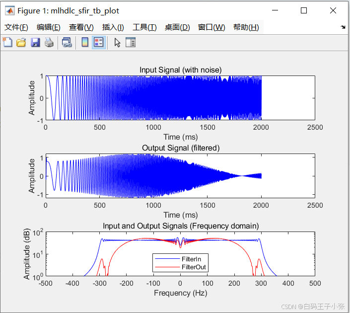
三、测试MATLAB算法
为了避免运行时错误,请使用测试台模拟设计。
在Matlab命令窗口输入:mlhdlc_sfir_tb
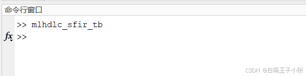
测试结果:
四、创建HDL Coder工程
创建一个HDL Coder项目:
1、在MATLAB编辑器中,在“APP”选项卡中选择HDL Coder。输入sfir_project作为项目的名称。
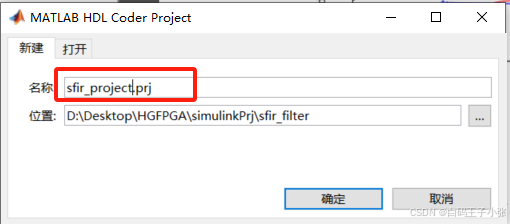
或者要从MATLAB命令窗口创建一个项目,运行以下命令:
coder -hdlcoder -new sfir_project
在当前文件夹中创建sfir_project.prj
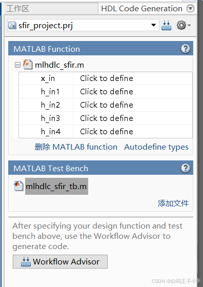
2、在HDL代码生成窗格中,在MATLAB函数部分,单击添加MATLAB函数,选择MATLAB设计的FIR滤波器mlhdlc_sfir.m。在MATLAB 测试台部分,单击添加文件并添加MATLAB测试台mlhdlc_sfir_tb.m。
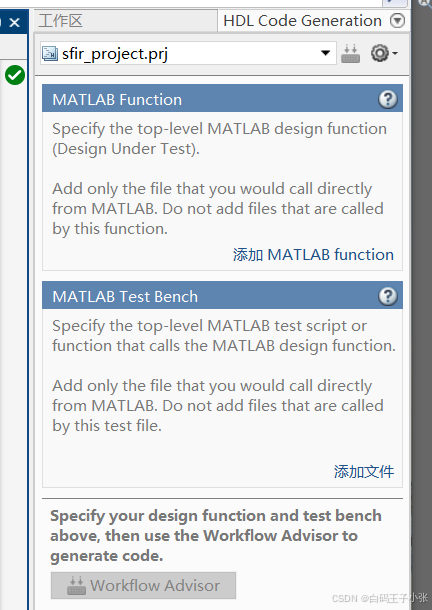
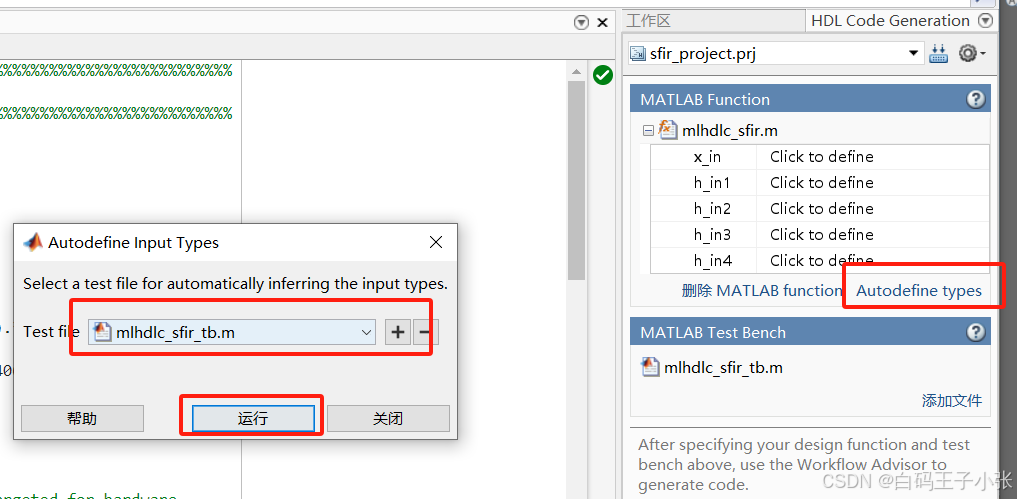
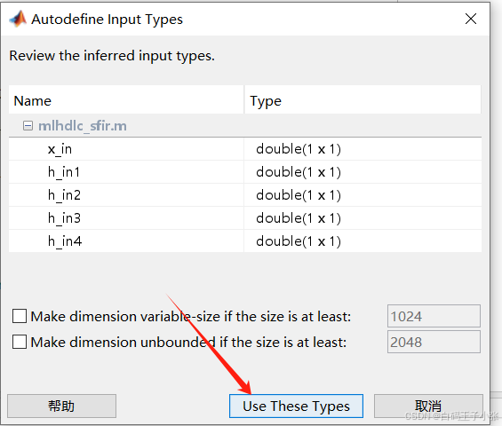
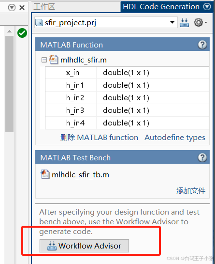
3、在HDL Code Generation窗格的MATLAB Function部分中,单击Autodefine types并使用MATLAB设计的推荐类型。代码生成器从MATLAB测试台推断输入类型。
五、运行定点转换和HDL代码生成
1、在“HDL Code Generation”窗格中,单击“Workflow Advisor”按钮以启动HDL Workflow Advisor。
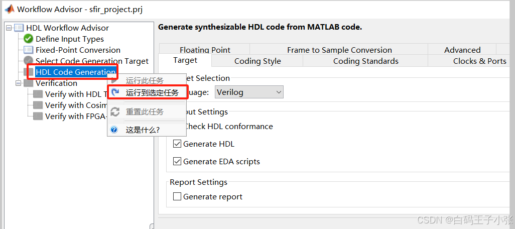
2、先更改HDL语言,这里使用Verilog语言,右键单击“HDL Code Generation”任务,选择“Run to selected task”。
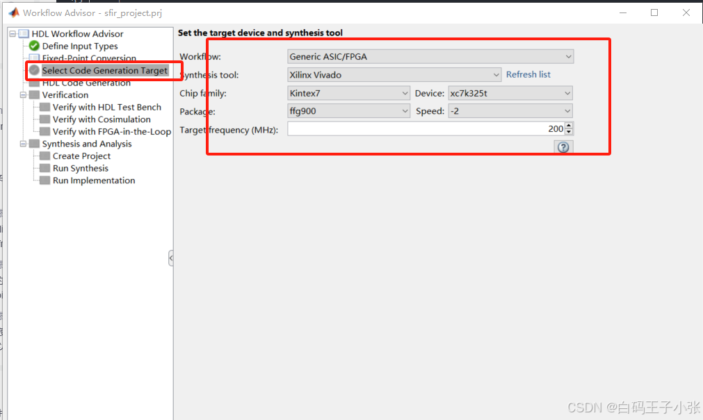
根据自己情况设置目标设备信息:
代码生成器运行Workflow Advisor任务,为过滤器设计生成HDL代码。
- 将您的浮点MATLAB设计转换为定点设计。若要检查从浮点设计生成的定点代码,请单击定点转换任务。生成的定点MATLAB代码在MATLAB编辑器中打开。具体操作请参见“Floating-Point to Fixed-Point Conversion”。
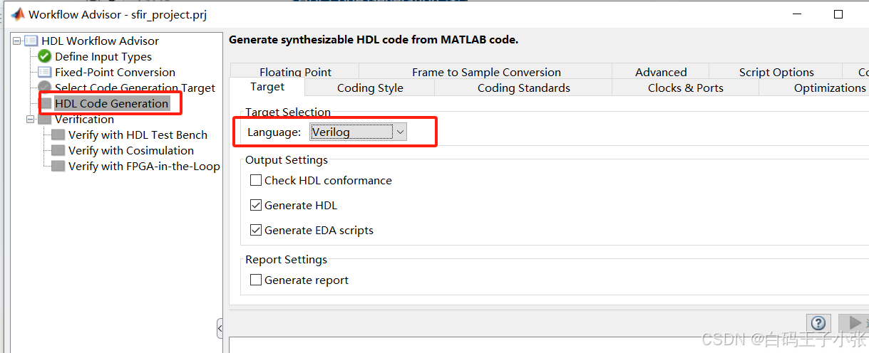
- 从MATLAB定点生成HDL代码设计。默认情况下,HDL Coder生成VHDL代码。要检查生成的HDL代码,请单击HDL代码生成任务,然后单击指向mlhdlc_sfir_fixpt的超链接。vhd在代码生成日志窗口。若要生成Verilog代码,请在“HDL Code Generation”任务中选择“Target”页签,并将“Language”设置为Verilog。有关更多信息和学习如何指定代码生成选项,请参阅“MATLAB to HDL Code and Synthesis”。
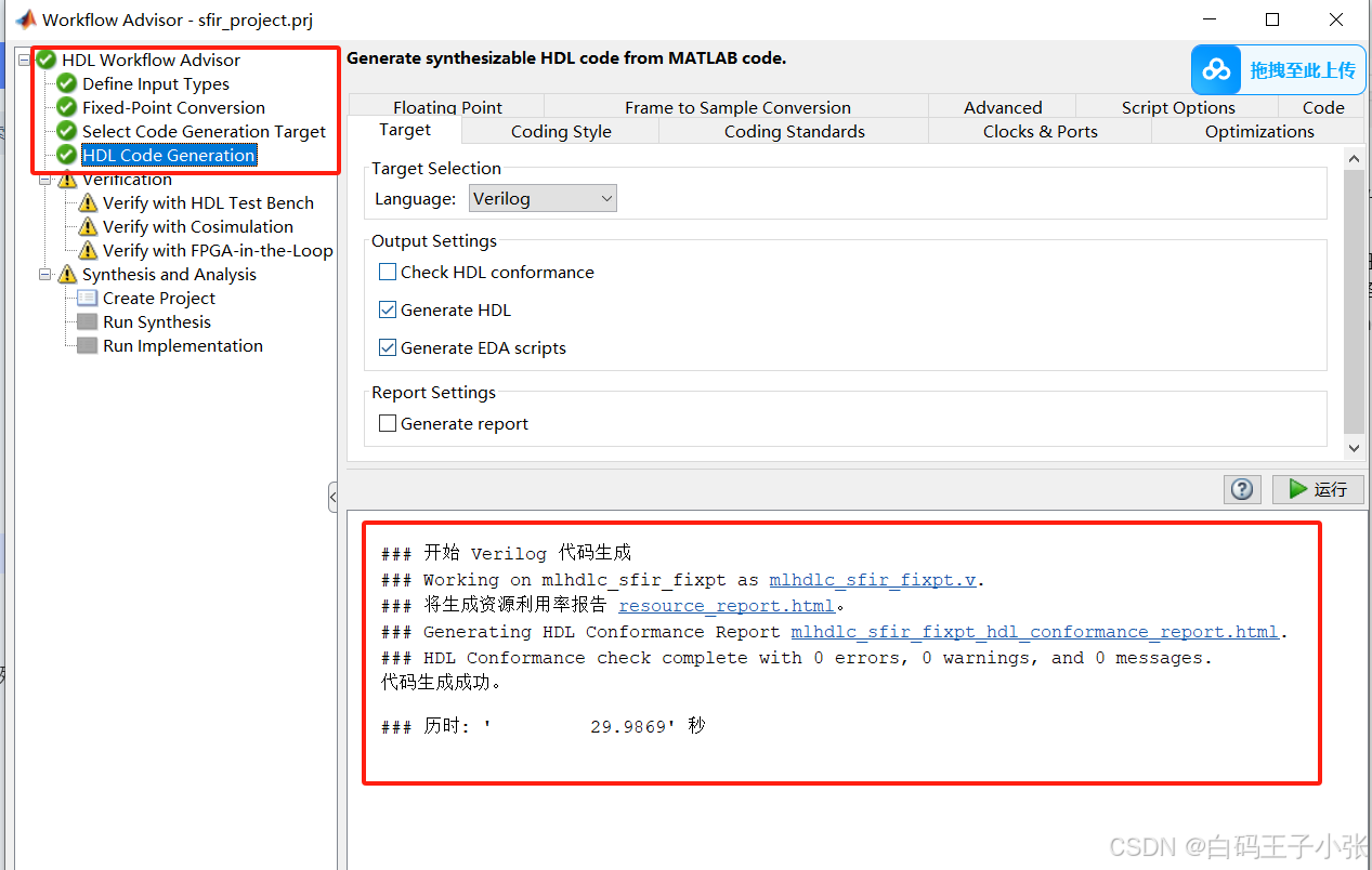
生成代码完成。
六、查看生成的Verilig代码
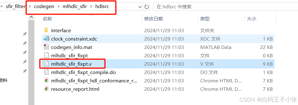
// -------------------------------------------------------------
//
// File Name: D:\Desktop\HGFPGA\simulinkPrj\sfir_filter\codegen\mlhdlc_sfir\hdlsrc\mlhdlc_sfir_fixpt.v
// Created: 2024-11-29 11:03:30
//
// Generated by MATLAB 24.1, MATLAB Coder 24.1 and HDL Coder 24.1
//
//
//
// -- -------------------------------------------------------------
// -- Rate and Clocking Details
// -- -------------------------------------------------------------
// Design base rate: 1
//
//
// Clock Enable  Sample Time
// -- -------------------------------------------------------------
// ce_out        1
// -- -------------------------------------------------------------
//
//
// Output Signal                 Clock Enable  Sample Time
// -- -------------------------------------------------------------
// y_out                         ce_out        1
// delayed_xout                  ce_out        1
// -- -------------------------------------------------------------
//
// -------------------------------------------------------------


// -------------------------------------------------------------
//
// Module: mlhdlc_sfir_fixpt
// Source Path: mlhdlc_sfir_fixpt
// Hierarchy Level: 0
//
// -------------------------------------------------------------

`timescale 1 ns / 1 ns

module mlhdlc_sfir_fixpt
          (clk,
           reset,
           clk_enable,
           x_in,
           h_in1,
           h_in2,
           h_in3,
           h_in4,
           ce_out,
           y_out,
           delayed_xout);


  input   clk;
  input   reset;
  input   clk_enable;
  input   signed [13:0] x_in;  // sfix14_En12
  input   signed [13:0] h_in1;  // sfix14_En15
  input   signed [13:0] h_in2;  // sfix14_En16
  input   [13:0] h_in3;  // ufix14_En16
  input   [13:0] h_in4;  // ufix14_En15
  output  ce_out;
  output  signed [13:0] y_out;  // sfix14_En12
  output  signed [13:0] delayed_xout;  // sfix14_En12


  wire enb;
  reg signed [13:0] ud1;  // sfix14_En12
  reg signed [13:0] ud2;  // sfix14_En12
  reg signed [13:0] ud3;  // sfix14_En12
  reg signed [13:0] ud4;  // sfix14_En12
  reg signed [13:0] ud5;  // sfix14_En12
  reg signed [13:0] ud6;  // sfix14_En12
  reg signed [13:0] ud7;  // sfix14_En12
  reg signed [13:0] ud8;  // sfix14_En12
  wire signed [13:0] a1;  // sfix14_En12
  wire signed [13:0] m1;  // sfix14_En14
  wire signed [27:0] p20m1_mul_temp;  // sfix28_En27
  wire signed [13:0] a2;  // sfix14_En12
  wire signed [13:0] a3;  // sfix14_En12
  wire signed [13:0] m3;  // sfix14_En14
  wire signed [14:0] p22m3_cast;  // sfix15_En16
  wire signed [28:0] p22m3_mul_temp;  // sfix29_En28
  wire signed [27:0] p22m3_cast_1;  // sfix28_En28
  wire signed [13:0] a4;  // sfix14_En11
  wire signed [14:0] p19a4_add_cast;  // sfix15_En12
  wire signed [14:0] p19a4_add_cast_1;  // sfix15_En12
  wire signed [14:0] p19a4_add_temp;  // sfix15_En12
  wire signed [13:0] m2;  // sfix14_En15
  wire signed [27:0] p21m2_mul_temp;  // sfix28_En28
  wire signed [13:0] a5;  // sfix14_En14
  wire signed [15:0] p24a5_add_cast;  // sfix16_En15
  wire signed [15:0] p24a5_add_cast_1;  // sfix16_En15
  wire signed [15:0] p24a5_add_temp;  // sfix16_En15
  wire signed [13:0] m4;  // sfix14_En13
  wire signed [14:0] p23m4_cast;  // sfix15_En15
  wire signed [28:0] p23m4_mul_temp;  // sfix29_En26
  wire signed [27:0] p23m4_cast_1;  // sfix28_En26
  wire signed [13:0] a6;  // sfix14_En12
  wire signed [15:0] p25a6_add_cast;  // sfix16_En14
  wire signed [15:0] p25a6_add_cast_1;  // sfix16_En14
  wire signed [15:0] p25a6_add_temp;  // sfix16_En14
  wire signed [16:0] p26y_out_add_cast;  // sfix17_En14
  wire signed [16:0] p26y_out_add_cast_1;  // sfix17_En14
  wire signed [16:0] p26y_out_add_temp;  // sfix17_En14


  assign enb = clk_enable;

  // %%%%%%%%%%%%%%%%%%%%%%%%%%%%%%%%%%%%%%%%%%%%%%%%%%%%%%%%%%%%%%%%%%%%%%%%%%%
  //                                                                          %
  //          Generated by MATLAB 24.1 and Fixed-Point Designer 24.1          %
  //                                                                          %
  // %%%%%%%%%%%%%%%%%%%%%%%%%%%%%%%%%%%%%%%%%%%%%%%%%%%%%%%%%%%%%%%%%%%%%%%%%%%
  // %%%%%%%%%%%%%%%%%%%%%%%%%%%%%%%%%%%%%%%%%%%%%%%%%%%%%%%%%%%%%%%%%%%%%%%%%
  // MATLAB design: Symmetric FIR Filter
  //
  // Introduction:
  // We can reduce the complexity of the FIR filter by leveraging its symmetry.
  // Symmetry for an n-tap filter implies, coefficient h0 = coefficient hn-1,
  // coefficient, h1 = coefficient hn-2, etc. In this case, the number of
  // multipliers can be approximately halved. The key is to add the
  // two data values that need to be multiplied with the same coefficient
  // prior to performing the multiplication.
  // Key Design pattern covered in this example:
  // (1) Filter states represented using the persistent variables
  // (2) Filter coefficients passed in as parameters
  //   Copyright 2011-2019 The MathWorks, Inc.
  // Symmetric FIR Filter
  // declare and initialize the delay registers
  // access the previous value of states/registers
  always @(posedge clk or posedge reset)
    begin : ud1_reg_process
      if (reset == 1'b1) begin
        ud1 <= 14'sb00000000000000;
      end
      else begin
        if (enb) begin
          ud1 <= x_in;
        end
      end
    end


  always @(posedge clk or posedge reset)
    begin : ud2_reg_process
      if (reset == 1'b1) begin
        ud2 <= 14'sb00000000000000;
      end
      else begin
        if (enb) begin
          ud2 <= ud1;
        end
      end
    end


  always @(posedge clk or posedge reset)
    begin : ud3_reg_process
      if (reset == 1'b1) begin
        ud3 <= 14'sb00000000000000;
      end
      else begin
        if (enb) begin
          ud3 <= ud2;
        end
      end
    end


  always @(posedge clk or posedge reset)
    begin : ud4_reg_process
      if (reset == 1'b1) begin
        ud4 <= 14'sb00000000000000;
      end
      else begin
        if (enb) begin
          ud4 <= ud3;
        end
      end
    end


  always @(posedge clk or posedge reset)
    begin : ud5_reg_process
      if (reset == 1'b1) begin
        ud5 <= 14'sb00000000000000;
      end
      else begin
        if (enb) begin
          ud5 <= ud4;
        end
      end
    end


  always @(posedge clk or posedge reset)
    begin : ud6_reg_process
      if (reset == 1'b1) begin
        ud6 <= 14'sb00000000000000;
      end
      else begin
        if (enb) begin
          ud6 <= ud5;
        end
      end
    end


  always @(posedge clk or posedge reset)
    begin : ud7_reg_process
      if (reset == 1'b1) begin
        ud7 <= 14'sb00000000000000;
      end
      else begin
        if (enb) begin
          ud7 <= ud6;
        end
      end
    end


  // update the delay line
  // delayout input signal
  always @(posedge clk or posedge reset)
    begin : ud8_reg_process
      if (reset == 1'b1) begin
        ud8 <= 14'sb00000000000000;
      end
      else begin
        if (enb) begin
          ud8 <= ud7;
        end
      end
    end


  assign a1 = ud1 + ud8;


  // multiplier chain
  assign p20m1_mul_temp = h_in1 * a1;
  assign m1 = p20m1_mul_temp[26:13];


  assign a2 = ud2 + ud7;


  assign a3 = ud3 + ud6;


  assign p22m3_cast = {1'b0, h_in3};
  assign p22m3_mul_temp = p22m3_cast * a3;
  assign p22m3_cast_1 = p22m3_mul_temp[27:0];
  assign m3 = p22m3_cast_1[27:14];


  assign p19a4_add_cast = {ud4[13], ud4};
  assign p19a4_add_cast_1 = {ud5[13], ud5};
  assign p19a4_add_temp = p19a4_add_cast + p19a4_add_cast_1;
  assign a4 = p19a4_add_temp[14:1];


  assign p21m2_mul_temp = h_in2 * a2;
  assign m2 = p21m2_mul_temp[26:13];


  // adder chain
  assign p24a5_add_cast = {m1[13], {m1, 1'b0}};
  assign p24a5_add_cast_1 = {{2{m2[13]}}, m2};
  assign p24a5_add_temp = p24a5_add_cast + p24a5_add_cast_1;
  assign a5 = p24a5_add_temp[14:1];


  assign p23m4_cast = {1'b0, h_in4};
  assign p23m4_mul_temp = p23m4_cast * a4;
  assign p23m4_cast_1 = p23m4_mul_temp[27:0];
  assign m4 = p23m4_cast_1[26:13];


  assign p25a6_add_cast = {{2{m3[13]}}, m3};
  assign p25a6_add_cast_1 = {m4[13], {m4, 1'b0}};
  assign p25a6_add_temp = p25a6_add_cast + p25a6_add_cast_1;
  assign a6 = p25a6_add_temp[15:2];


  // filtered output
  assign p26y_out_add_cast = {{3{a5[13]}}, a5};
  assign p26y_out_add_cast_1 = {a6[13], {a6, 2'b00}};
  assign p26y_out_add_temp = p26y_out_add_cast + p26y_out_add_cast_1;
  assign y_out = p26y_out_add_temp[15:2];


  assign ce_out = clk_enable;

  assign delayed_xout = ud8;

endmodule  // mlhdlc_sfir_fixpt


 593
593


 到【灌水乐园】发言


