


 本文介绍了一种利用单个IC实现正负12V双极性电源供电的设计方案。该方案采用高频开关转换器,通过三个小型电感代替传统变压器,显著减小了电路尺寸并降低了高度。同时,该设计支持宽范围输入电压,能够从3V到10V的电源产生稳定的±5V输出,并可在待机模式下断开两个输出以降低静态电流。
Dual-polarity supply provides ±12V from one IC
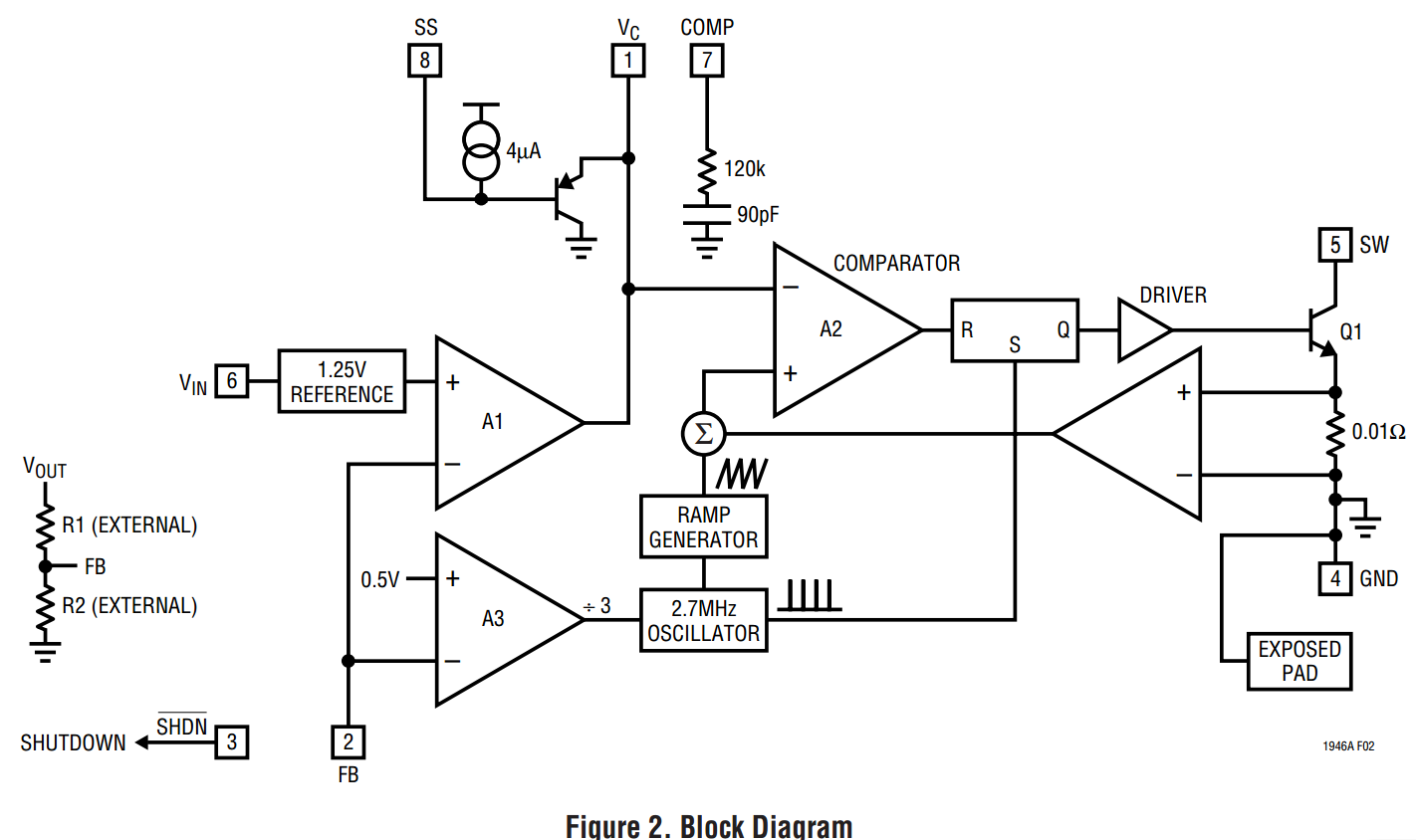
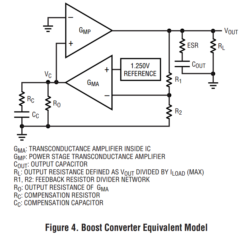
VC (Pin 1): Error Amplifier Output Pin. Tie external compensation network to this pin or use the internal compensation network by shorting the VC pin to the COMP pin.
External compensation consists of placing a resistor and capacitor in series from VC to GND. Typical capacitor range is from 90pF to 270pF. Typical resistor range is from 25k to 120k.
FB (Pin 2): Feedback Pin. Reference voltage is 1.25V. Connect resistive divider tap here. Minimize trace area at FB. Set VOUT according to VOUT = 1.25 • (1+R1/R2).
SHDN (Pin 3): Shutdown Pin. Tie to 2.4V or more to enable device. Ground to shut down. Do not float this pin.
GND (Pin 4, Exposed Pad): Ground. Tie both Pin 4 and the exposed pad directly to local ground plane. The ground metal to the exposed pad should be wide for better heat dissipation.
Multiple vias (local ground plane ↔ ground backplane) placed close to the exposed pad can further aid in reducing thermal resistance.
SW (Pin 5): Switch Pin. This is the collector of the internal NPN power switch. Minimize the metal trace area connected to this pin to minimize EMI.
VIN (Pin 6): Input Supply Pin. Must be locally bypassed.
COMP (Pin 7): Internal Compensation Pin. Provides an internal compensation network. Tie directly to the VC pin for internal compensation. Tie to GND if not used.
SS (Pin 8): Soft-Start Pin. Place a soft-start capacitor here. Upon start-up, 4µA of current charges the capacitor to 1.5V. Use a larger capacitor for slower start-up. Leave floating if not in use.
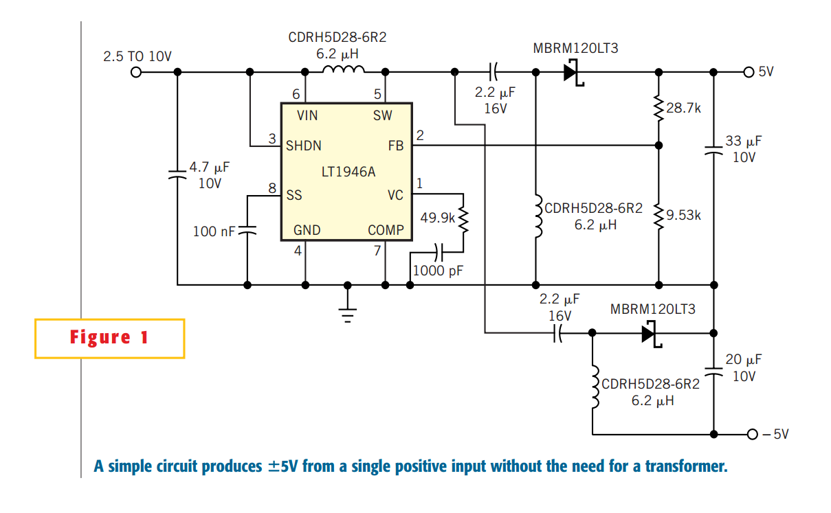
The conventional way to produce dual (positive and negative) outputs from a single positive input is to use a transformer. Although such designs are relatively simple, the transformer inherently introduces the problem of size. It can be challenging to fit a transformer into an application in which it's important to minimize the circuit footprint and height. The circuit in Figure 1 generates ±5V from a 3 to 10V input and fits into applications that lack the room to accommodate a transformer. The circuit uses a topology that allows the disconnection of both outputs when the dc/dc converter is in shutdown mode; thus, the quiescent current is low during shutdown (standby) mode. The circuit also produces a regulated positive and negative 5V, regardless of whether the input is higher or lower than 5V. Therefore, the circuit can operate from various input sources, such as a 3 to 4.2V lithium-ion battery or a 3.3 to 10V wall adapter. By slightly modifying the circuit, you can increase the input range to 2.5 to 16V and the output range to 3 to 12V.
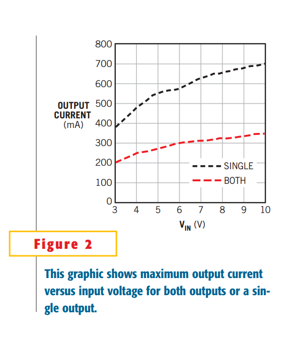
The 2.7-MHz switching frequency of the dc/dc converter allows the use of small, low-profile external components (input/output capacitors and inductors). Using three small inductors instead of one bulky transformer not only reduces the size and height of the converter, but also evenly distributes the power dissipation over the board, thus eliminating concentrated hot spots. The output-current capability of the circuit increases as the input voltage increases (higher input voltage, lower input current).Figure 2 shows the maximum output current versus the input voltage. The "both" curve represents the maximum allowable output current of both ±5V outputs when you load them with the same current. The "single" curve represents the maximum allowable output current of each output when you load either output alone. When the current from one output decreases, the current capability of the other output increases, as long as you do not exceed the current rating of the dc/dc converter.
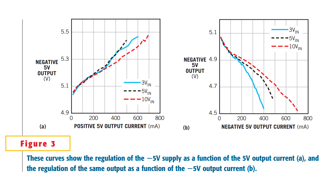
Cross-load regulation is another important design consideration in this type of circuit. Because the –5V output does not have control of the dc/dc converter's PWM feedback, the –5V output voltage changes with output current. You can greatly improve the cross-load regulation by adding a 10- to 20-mA preload at each output. The preload ensures that the dc/dc converter operates in continuous-conduction mode, in which the inductor current is stable enough to provide constant current.Figure 3 shows the –5V output voltage regulation under different load conditions at the positive (Figure 3a) and negative (Figure 3b) outputs. In this case, to improve cross-load regulation, both the outputs connect to a 20-mA preload.


 9658
9658

 被折叠的 条评论
为什么被折叠?
被折叠的 条评论
为什么被折叠?
 到【灌水乐园】发言


