


 本文介绍如何使用Arduino驱动1.8寸TFT屏,详细讲解了硬件连接方式及软件配置过程,包括所需的库文件及关键代码片段。
在合宙通信买了一个1.8寸的TFT屏,驱动芯片是ST7533,本来打算使用Air800直接驱动,但由于其他原因,放弃了。于是尝试使用arduino驱动,为了屏幕刷新速度更快,采用硬件SPI。
硬件连接
屏幕引脚如下图所示:
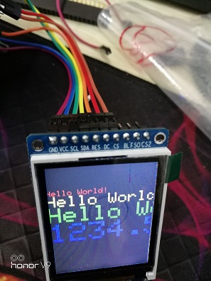
主要用到的引脚有:
GND:地
VCC:电源
SCL:时钟
SDA:数据
RES:复位
DC:数据/命令选择
CS:片选
分别对应arduino的以下引脚:
GND:地 —————— GND
VCC:电源 —————— VCC
SCL:时钟 —————— SPI_SCL(D13)
SDA:数据 —————— SPI_MOSI(D11)
RES:复位 —————— D8
DC:数据/命令选择 —————— D9
CS:片选 —————— D10
程序部分
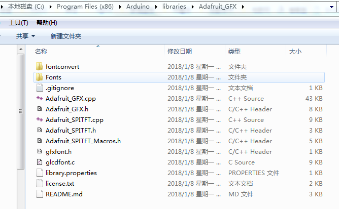
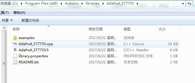
下载以下两个库:Adafruit GFX 程序,Adafruit ST7735 程序库,然后解压到Arduino IDE安装文件下的libraries文件夹下。
结果如下图:
打开Adafruit_ST7735/examples/graphicstest/graphicstest.ino文件,根据上述引脚连接,修改以下代码:
// For the breakout, you can use any 2 or 3 pins
// These pins will also work for the 1.8" TFT shield
#define TFT_CS     10
#define TFT_RST    8  // you can also connect this to the Arduino reset
                      // in which case, set this #define pin to -1!
#define TFT_DC     9

// Option 1 (recommended): must use the hardware SPI pins
// (for UNO thats sclk = 13 and sid = 11) and pin 10 must be
// an output. This is much faster - also required if you want
// to use the microSD card (see the image drawing example)
Adafruit_ST7735 tft = Adafruit_ST7735(TFT_CS,  TFT_DC, TFT_RST);

// Option 2: use any pins but a little slower!
#define TFT_SCLK 13   // set these to be whatever pins you like!
#define TFT_MOSI 11   // set these to be whatever pins you like!
//Adafruit_ST7735 tft = Adafruit_ST7735(TFT_CS, TFT_DC, TFT_MOSI, TFT_SCLK, TFT_RST);


 2648
2648

 被折叠的 条评论
为什么被折叠?
被折叠的 条评论
为什么被折叠?
 到【灌水乐园】发言


