 使用Vivado配置Zynq EMIO点亮LED灯


 本文档详细介绍了如何在Vivado 2017.4环境下,针对Zedboard(XC7Z020CLG484-1芯片)开发板,通过配置EMIO(扩展I/O)来控制FPGA侧的8个LED灯。首先,区分了MIO和EMIO的区别,然后展示了新建Vivado工程、导入Zynq核、配置EMIO为8个管脚的步骤。接着,通过设置管脚约束并生成bit文件,最后在SDK中创建FSBL和hello_world应用项目,实现LED灯的点亮和熄灭功能。代码示例展示了如何设置端口方向和使能,以达到控制LED灯的目的。
开发板环境:vivado2017.4
开发板:Zedboard 芯片型号:xc7z020clg484-1
在zynq中分为MIO和EMIO,MIO是arm端的管脚,而EMIO是将arm端的管脚使用fpga管脚来进行扩展,本章主要使用EMIO来点亮LED灯
EMIO0~EMIO63一共64个管脚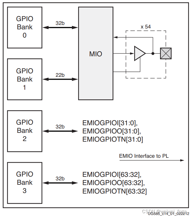
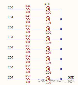
EMIO0~EMIO63一共64个管脚,这里只控制FPGA侧的LED一共八个,硬件连接如下图所示
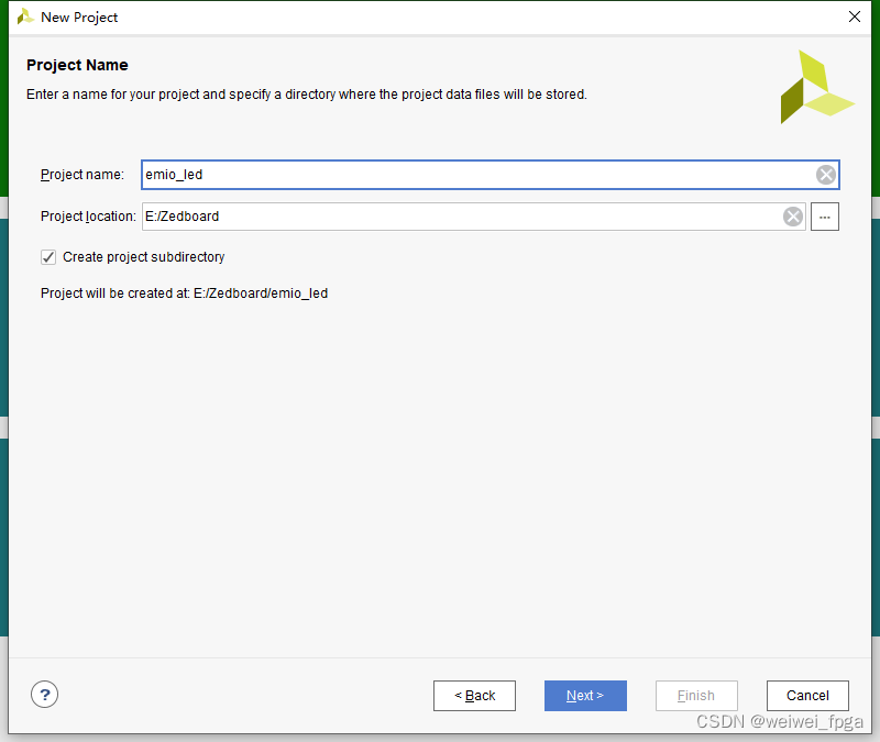
新建工程vivado工程
新建工程后,调用zynq核
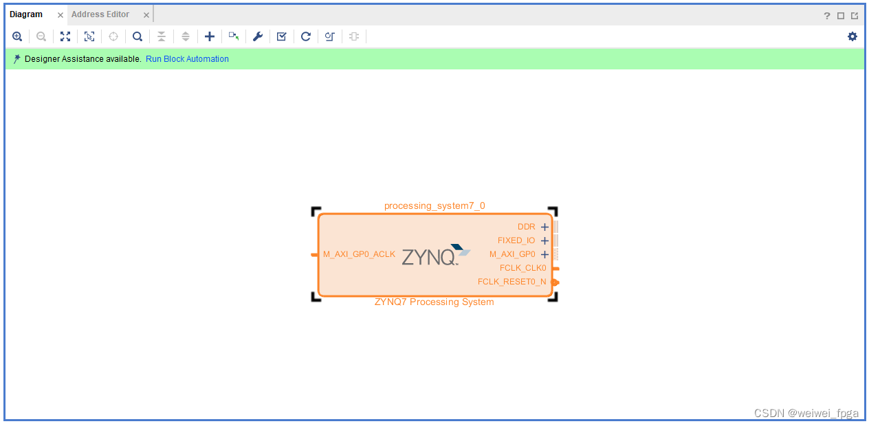
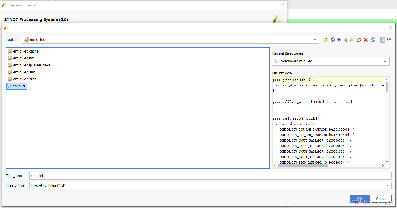
导入配置文件emio.tcl
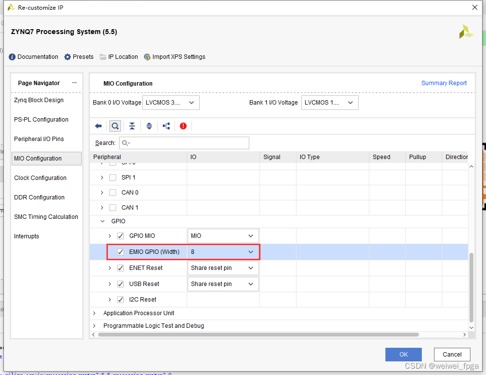
配置后将EMIO项设置为8个,对应我们控制的八个LED灯
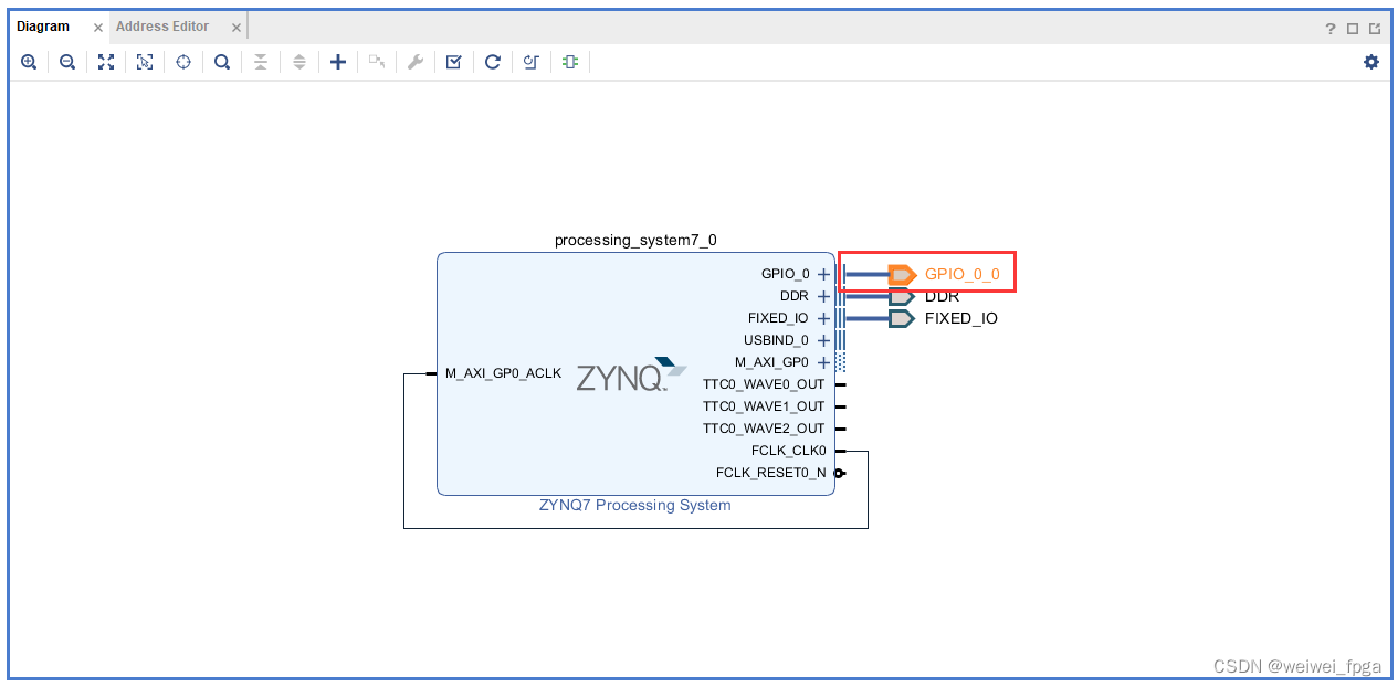
新建好的zynq核
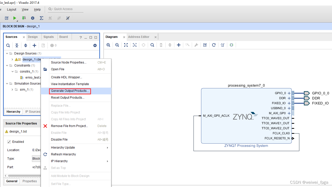
生成综合文件
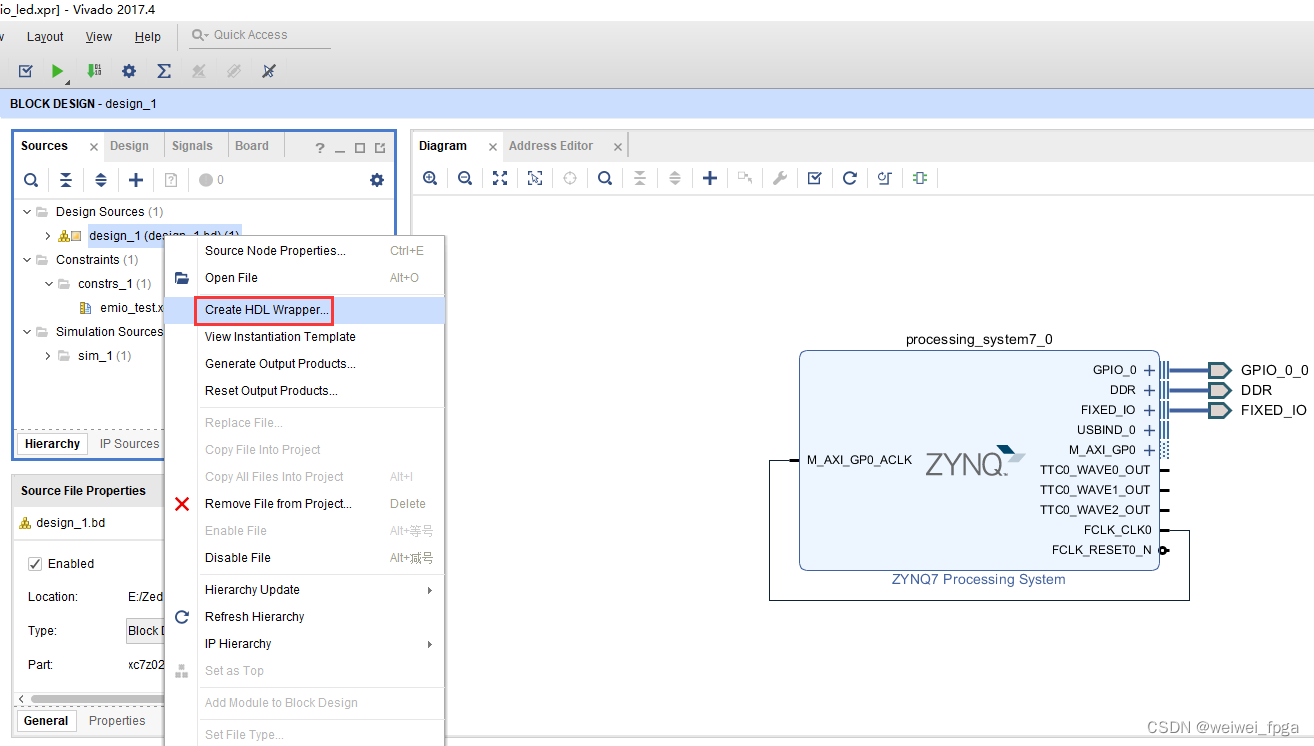
生成顶层文件
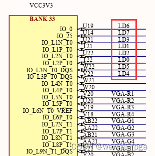
管脚约束
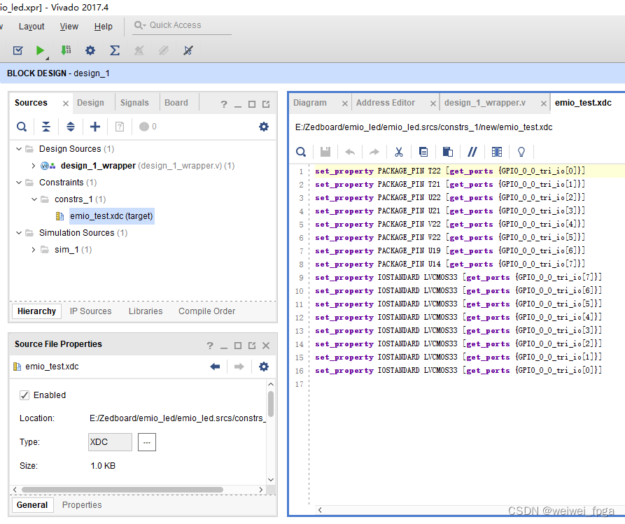
set_property PACKAGE_PIN T22 [get_ports {GPIO_0_0_tri_io[0]}]
set_property PACKAGE_PIN T21 [get_ports {GPIO_0_0_tri_io[1]}]
set_property PACKAGE_PIN U22 [get_ports {GPIO_0_0_tri_io[2]}]
set_property PACKAGE_PIN U21 [get_ports {GPIO_0_0_tri_io[3]}]
set_property PACKAGE_PIN V22 [get_ports {GPIO_0_0_tri_io[4]}]
set_property PACKAGE_PIN W22 [get_ports {GPIO_0_0_tri_io[5]}]
set_property PACKAGE_PIN U19 [get_ports {GPIO_0_0_tri_io[6]}]
set_property PACKAGE_PIN U14 [get_ports {GPIO_0_0_tri_io[7]}]
set_property IOSTANDARD LVCMOS33 [get_ports {GPIO_0_0_tri_io[7]}]
set_property IOSTANDARD LVCMOS33 [get_ports {GPIO_0_0_tri_io[6]}]
set_property IOSTANDARD LVCMOS33 [get_ports {GPIO_0_0_tri_io[5]}]
set_property IOSTANDARD LVCMOS33 [get_ports {GPIO_0_0_tri_io[4]}]
set_property IOSTANDARD LVCMOS33 [get_ports {GPIO_0_0_tri_io[3]}]
set_property IOSTANDARD LVCMOS33 [get_ports {GPIO_0_0_tri_io[2]}]
set_property IOSTANDARD LVCMOS33 [get_ports {GPIO_0_0_tri_io[1]}]
set_property IOSTANDARD LVCMOS33 [get_ports {GPIO_0_0_tri_io[0]}]
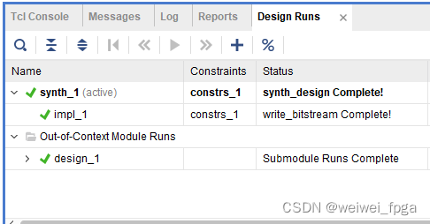
生成bit文件
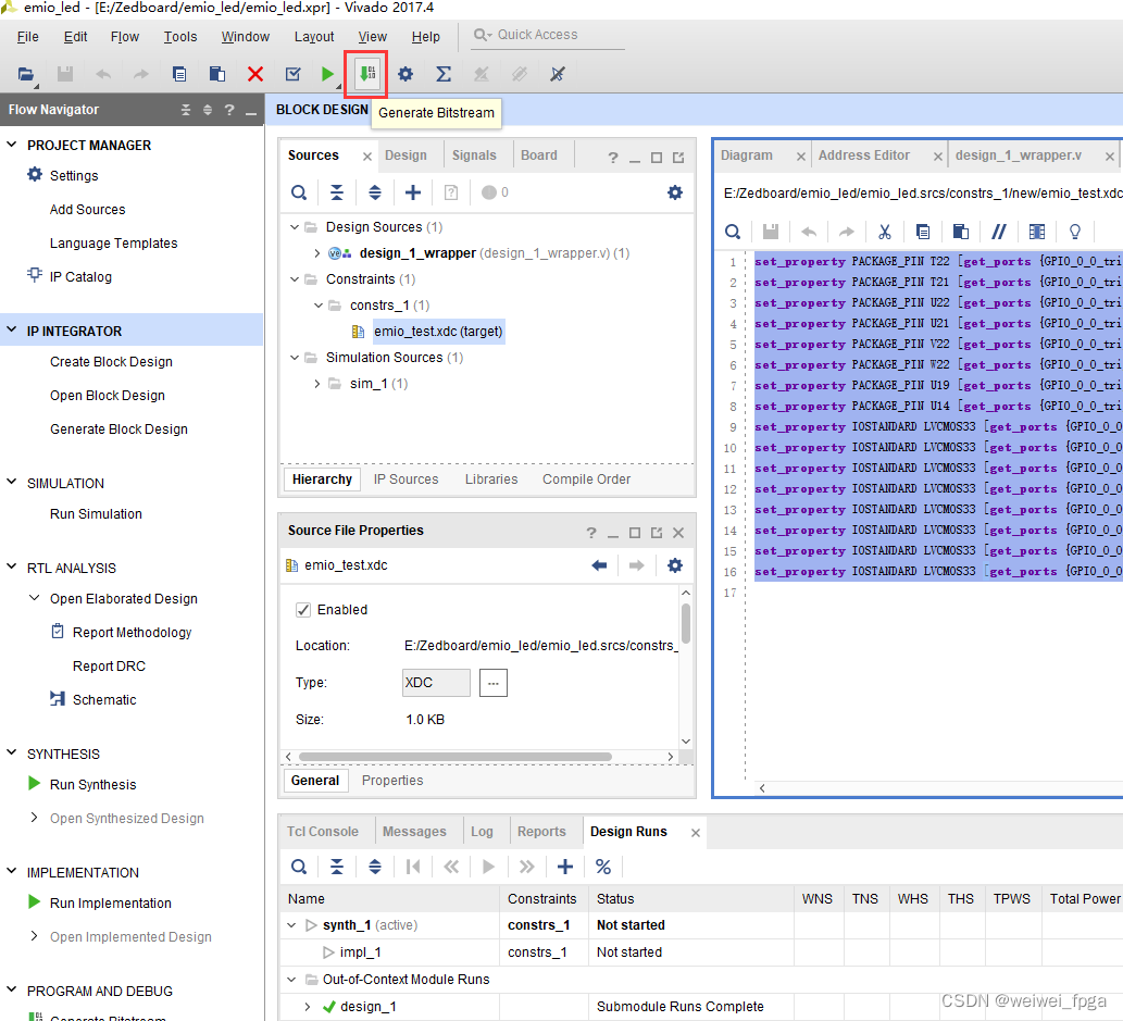
生成bit文件成功
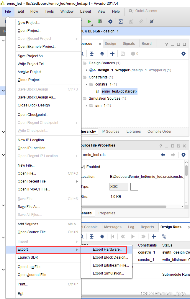
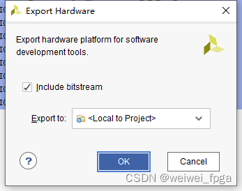
导出硬件配置
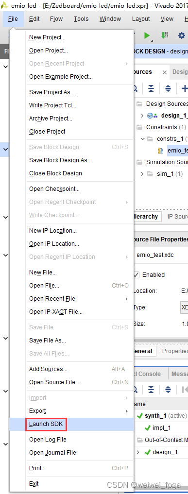
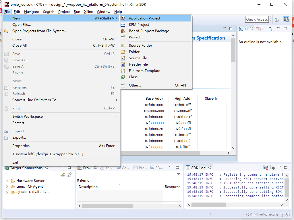
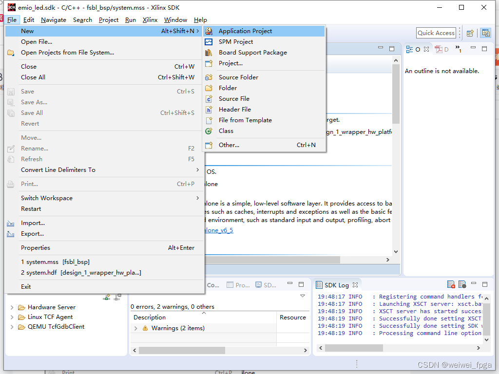
File-->Launch SDK打开SDK
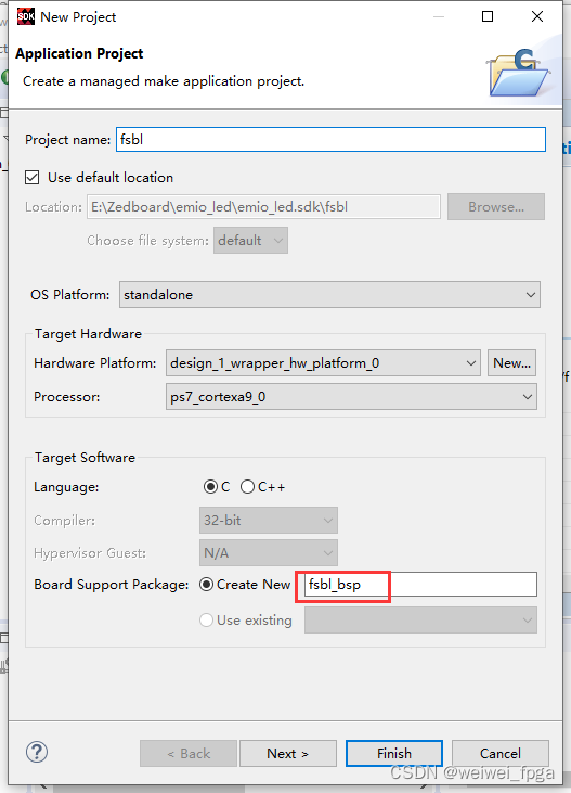
点击New-->application Project新建fsbl
 新建fsbl,点击Next
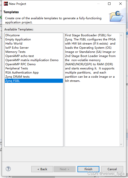
选择Zynq FSBL,点击Finish
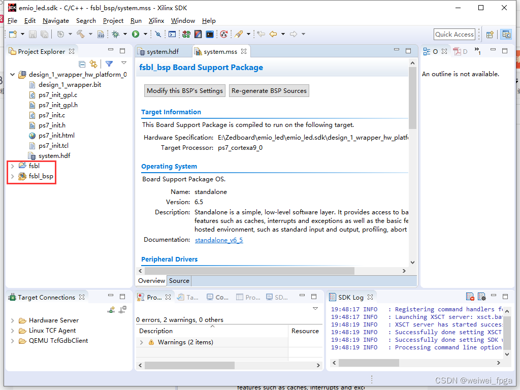
新建的fsbl
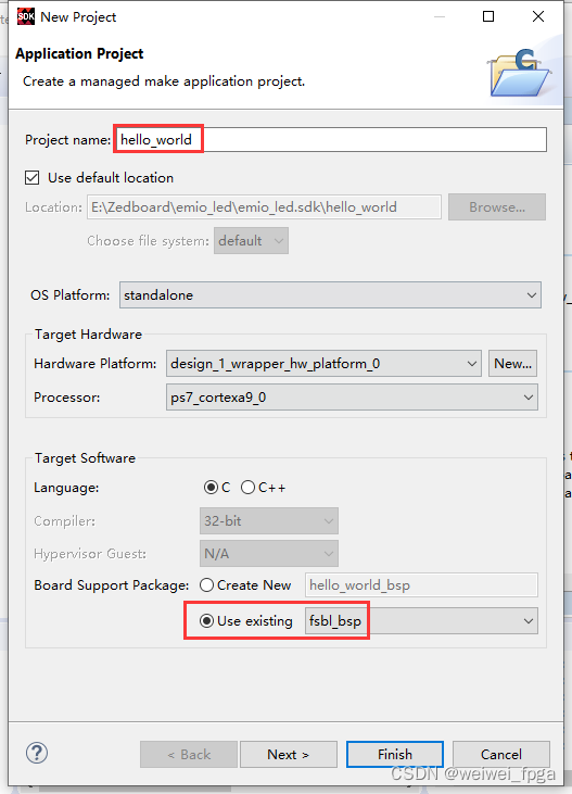
再次点击New-->application Project,新建一个hello_world工程
新建hello_world工程,点击Next
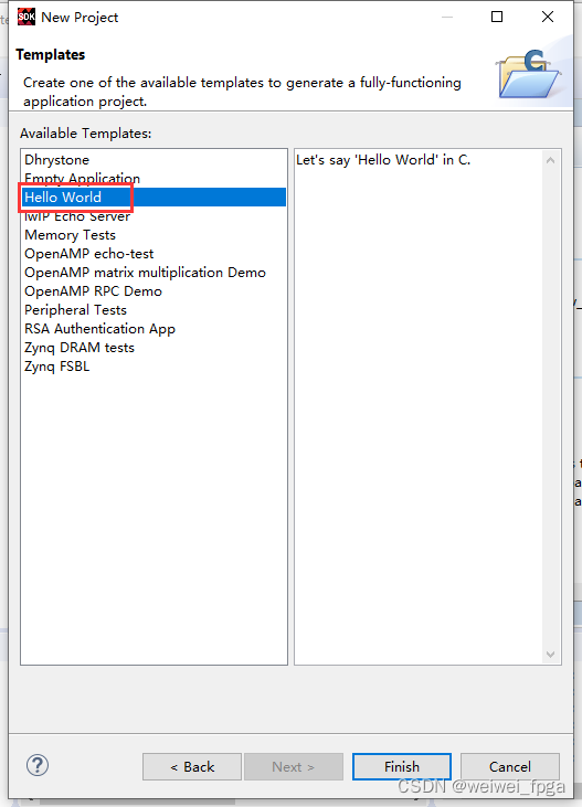
选择Hello World工程模板,点击Finish
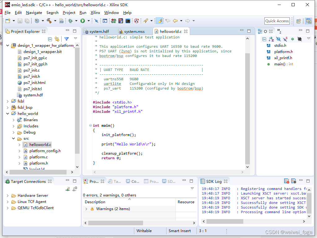
新建的hello_world工程
更改后的emio工程
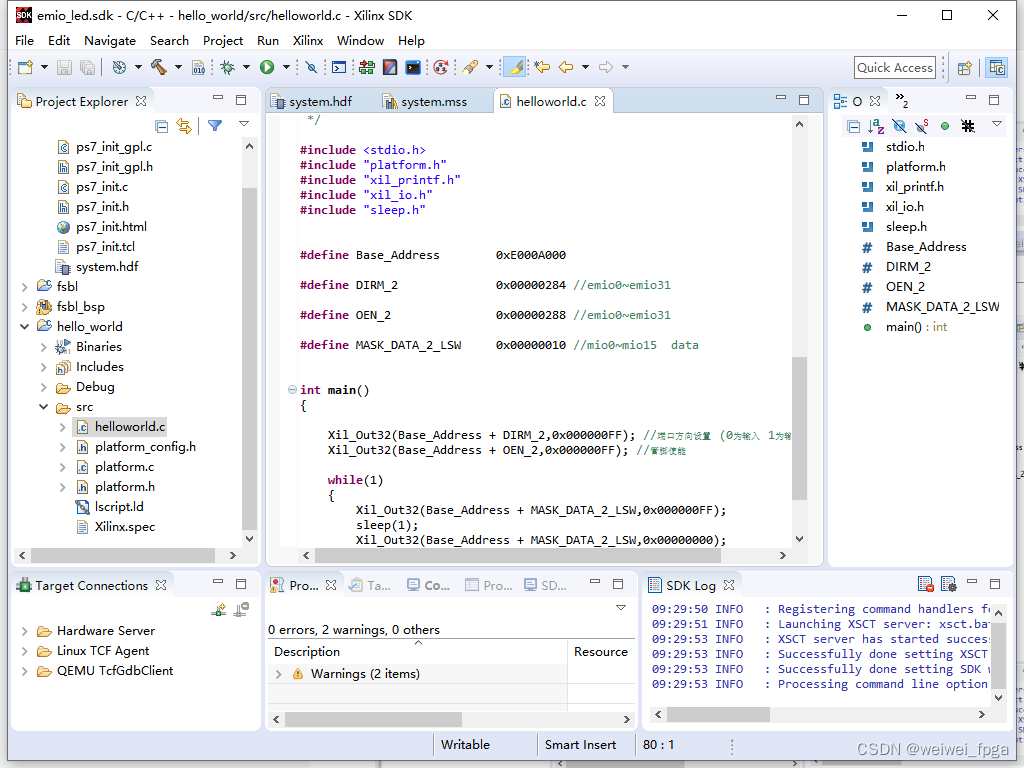
EMIO代码
/******************************************************************************
*
* Copyright (C) 2009 - 2014 Xilinx, Inc.  All rights reserved.
*
* Permission is hereby granted, free of charge, to any person obtaining a copy
* of this software and associated documentation files (the "Software"), to deal
* in the Software without restriction, including without limitation the rights
* to use, copy, modify, merge, publish, distribute, sublicense, and/or sell
* copies of the Software, and to permit persons to whom the Software is
* furnished to do so, subject to the following conditions:
*
* The above copyright notice and this permission notice shall be included in
* all copies or substantial portions of the Software.
*
* Use of the Software is limited solely to applications:
* (a) running on a Xilinx device, or
* (b) that interact with a Xilinx device through a bus or interconnect.
*
* THE SOFTWARE IS PROVIDED "AS IS", WITHOUT WARRANTY OF ANY KIND, EXPRESS OR
* IMPLIED, INCLUDING BUT NOT LIMITED TO THE WARRANTIES OF MERCHANTABILITY,
* FITNESS FOR A PARTICULAR PURPOSE AND NONINFRINGEMENT. IN NO EVENT SHALL
* XILINX  BE LIABLE FOR ANY CLAIM, DAMAGES OR OTHER LIABILITY,
* WHETHER IN AN ACTION OF CONTRACT, TORT OR OTHERWISE, ARISING FROM, OUT OF
* OR IN CONNECTION WITH THE SOFTWARE OR THE USE OR OTHER DEALINGS IN THE
* SOFTWARE.
*
* Except as contained in this notice, the name of the Xilinx shall not be used
* in advertising or otherwise to promote the sale, use or other dealings in
* this Software without prior written authorization from Xilinx.
*
******************************************************************************/

/*
 * helloworld.c: simple test application
 *
 * This application configures UART 16550 to baud rate 9600.
 * PS7 UART (Zynq) is not initialized by this application, since
 * bootrom/bsp configures it to baud rate 115200
 *
 * ------------------------------------------------
 * | UART TYPE   BAUD RATE                        |
 * ------------------------------------------------
 *   uartns550   9600
 *   uartlite    Configurable only in HW design
 *   ps7_uart    115200 (configured by bootrom/bsp)
 */

#include <stdio.h>
#include "platform.h"
#include "xil_printf.h"
#include "xil_io.h"
#include "sleep.h"


#define	Base_Address		0xE000A000

#define	DIRM_2				0x00000284 //emio0~emio31

#define	OEN_2				0x00000288 //emio0~emio31

#define	MASK_DATA_2_LSW		0x00000010 //mio0~mio15  data


int main()
{

	Xil_Out32(Base_Address + DIRM_2,0x000000FF); //端口方向设置 (0为输入  1为输出)
	Xil_Out32(Base_Address + OEN_2,0x000000FF); //管脚使能

	while(1)
	{
		Xil_Out32(Base_Address + MASK_DATA_2_LSW,0x000000FF);
		sleep(1);
		Xil_Out32(Base_Address + MASK_DATA_2_LSW,0x00000000);
		sleep(1);
	}


}
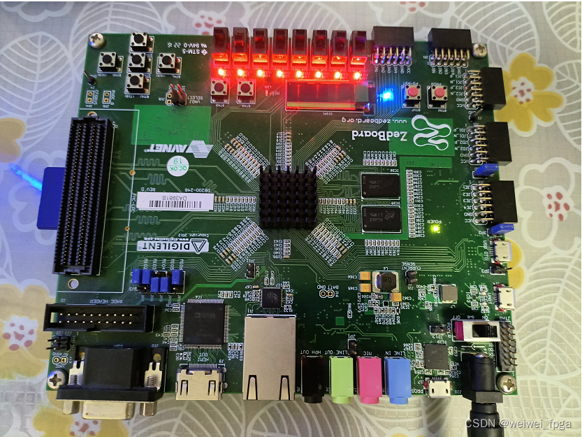
使用emio接口同时点亮8路led灯
使用emio接口同时熄灭8路led灯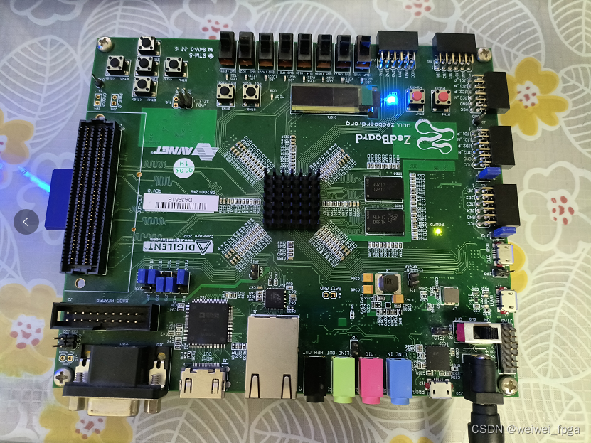


 2750
2750

 被折叠的 条评论
为什么被折叠?
被折叠的 条评论
为什么被折叠?
 到【灌水乐园】发言


