


Basic Facilities of a Virtio Device 一
- 1 Device Status Field
- 2 Feature Bits
- 3 Notifications
- 4 Device Reset
- 5 Device Configuration Space
- 6 Virtqueues
- 7 Split Virtqueues
- 7.1 Driver Requirements: Virtqueues
- 7.2 Legacy Interfaces: A Note on Virtqueue Layout
- 7.3 Legacy Interfaces: A Note on Virtqueue Endianness
- 7.4 Message Framing
- 7.5 The Virtqueue Descriptor Table
- 7.6 The Virtqueue Available Ring
- 7.7 Used Buffer Notification Suppression
- 7.8 The Virtqueue Used Ring
- 7.9 In-order use of descriptors
- 7.10 Available Buffer Notification Suppression
- 7.11 Helpers for Operating Virtqueues
- 7.12 Virtqueue Operation
- 7.13 Supplying Buffers to The Device
- 7.14 Receiving Used Buffers From The Device
- 8 Packed Virtqueues
- 8.1 Driver and Device Ring Wrap Counters
- 8.2 Polling of available and used descriptors
- 8.3 Write Flag
- 8.4 Element Address and Length
- 8.5 Scatter-Gather Support
- 8.6 Next Flag: Descriptor Chaining
- 8.7 Indirect Flag: Scatter-Gather Support
- 8.11 Driver Requirements: Virtqueues
- 8.12 Device Requirements: Virtqueues
- 8.13 The Virtqueue Descriptor Format
- 8.14 Event Suppression Structure Format
- 8.15 Device Requirements: The Virtqueue Descriptor Table
- 8.16 Driver Requirements: The Virtqueue Descriptor Table
- 8.17 Driver Requirements: Scatter-Gather Support
- 8.18 Device Requirements: Scatter-Gather Support
- 8.19 Driver Requirements: Indirect Descriptors
- 8.20 Virtqueue Operation
- 8.21 Supplying Buffers to The Device
- 8.22 Receiving Used Buffers From The Device
该文章是基于对virtio-1.2官方文档的翻译而成,virtio-1.2官方文档的下载地址为: http://docs.oasis-open.org/virtio/virtio/v1.2/
A virtio device is discovered and identified by a bus-specific method (see the bus specific sections: 4.1 Virtio Over PCI Bus, 4.2 Virtio Over MMIO and 4.3 Virtio Over Channel I/O). Each device consists of the following parts:
通过总线特定的方法发现和识别一个virtio设备(见总线特定部分:4.1通过PCI总线,4.2通过MMIO和4.3通过通道I/O)。每个设备由以下各部分组成:
- Device status field 设备状态域
- Feature bits 功能特性位
- Notifications 通知
- Device Configuration space 设备配置空间
- One or more virtqueues 一个或多个虚拟队列virtqueue
1 Device Status Field
During device initialization by a driver, the driver follows the sequence of steps specified in 3.1.
在驱动程序的设备初始化过程中,驱动程序遵循3.1中指定的步骤顺序。
The device status field provides a simple low-level indication of the completed steps of this sequence. It’s most useful to imagine it hooked up to traffic lights on the console indicating the status of each device. The following bits are defined (listed below in the order in which they would be typically set):
设备状态字段提供此序列完成步骤的简单低级指示。最有用的方法是想象它连接到控制台上的交通灯上,指示每个设备的状态。定义了以下位(下面按它们通常设置的顺序列出)
ACKNOWLEDGE (1) Indicates that the guest OS has found the device and recognized it as a valid virtio device.
确认(1)表示客户操作系统已找到该设备,并将其识别为有效的virtio 半虚拟化设备。
DRIVER (2) Indicates that the guest OS knows how to drive the device.
驱动程序(2)表示来宾操作系统知道如何驱动该设备。
Note: There could be a significant (or infinite) delay before setting this bit. For example, under Linux, drivers can be loadable modules.
注:在设置此位之前,可能存在重大(或无限)延迟。例如,在Linux下,驱动程序可以是可加载的模块。
FAILED (128) Indicates that something went wrong in the guest, and it has given up on the device. This could be an internal error, or the driver didn’t like the device for some reason, or even a fatal error during device operation.
失败的(128)表明guest出了问题,并且已经放弃了设备。这可能是一个内部错误,或者驱动程序由于某种原因不喜欢该设备,甚至是设备操作过程中的一个致命错误。
FEATURES_OK (8) Indicates that the driver has acknowledged all the features it understands, and feature negotiation is complete.
FEATURES_OK(8)表示驱动程序已确认了它所理解的所有功能,并且功能协商已完成。
DRIVER_OK (4) Indicates that the driver is set up and ready to drive the device.
DRIVER_OK(4)表示驱动程序已设置好并准备好驱动该设备。
DEVICE_NEEDS_RESET (64) Indicates that the device has experienced an error from which it can’t recover.
DEVICE_NEEDS_RESET(64)表示该设备经历了一个无法从中恢复的错误。
The device status field starts out as 0, and is reinitialized to 0 by the device during reset.
设备状态字段开始为0,并在重置期间由设备重新初始化为0。
1.1 Driver Requirements: Device Status Field
The driver MUST update device status, setting bits to indicate the completed steps of the driver initialization sequence specified in 3.1. The driver MUST NOT clear a device status bit. If the driver sets the FAILED bit, the driver MUST later reset the device before attempting to re-initialize.
驱动程序必须更新设备状态,设置位来表示3.1中指定的驱动程序初始化序列的已完成步骤。驱动程序不能清除设备状态位。如果驱动程序设置了FAILED 位,则驱动程序必须在尝试重新初始化之前重置设备。
The driver SHOULD NOT rely on completion of operations of a device if DEVICE_NEEDS_RESET is set.
如果设置了DEVICE_NEEDS_RESET,则驱动程序不应该依赖于设备操作的完成。
Note: For example, the driver can’t assume requests in flight will be completed if DEVICE_NEEDS_RESET is set, nor can it assume that they have not been completed. A good implementation will try to recover by issuing a reset.
注意:例如,如果设置了DEVICE_NEEDS_RESET,驱动程序不能假设正在处理的请求将会完成,也不能假设它们还没有完成。一个好的实现将尝试通过发出重置来恢复。
1.2 Device Requirements: Device Status Field
The device MUST NOT consume buffers or send any used buffer notifications to the driver before DRIVER_OK.
在DRIVER_OK之前,设备不能使用缓冲区或发送任何使用过的缓冲区通知给驱动程序。
The device SHOULD set DEVICE_NEEDS_RESET when it enters an error state that a reset is needed. If DRIVER_OK is set, after it sets DEVICE_NEEDS_RESET, the device MUST send a device configuration change notification to the driver.
当设备进入需要重置的错误状态时,设备应该设置DEVICE_NEEDS_RESET。如果设置了DRIVER_OK,则在设置了DEVICE_NEEDS_RESET后,设备必须向驱动程序发送设备配置更改通知
2 Feature Bits
Each virtio device offers all the features it understands. During device initialization, the driver reads this and tells the device the subset that it accepts. The only way to renegotiate is to reset the device.
每个virtio设备都提供了它所能理解的所有功能。在设备初始化期间,驱动程序会读取此内容,并告诉设备它所接受的子集。重新协商的唯一方法是重置设备。
This allows for forwards and backwards compatibility: if the device is enhanced with a new feature bit, older drivers will not write that feature bit back to the device. Similarly, if a driver is enhanced with a feature that the device doesn’t support, it see the new feature is not offered.
这允许向前和向后兼容性:如果设备增强了一个新的特性位,旧的驱动程序将不会将该特性位写回设备。类似地,如果一个驱动程序被设备不支持的功能增强,它会看到没有提供新功能。
Feature bits are allocated as follows:
功能特征位的分配方式如下:
0 to 23, and 50 to 127 Feature bits for the specific device type
0到23,和50到127特征位是特定设备类型
24 to 40 Feature bits reserved for extensions to the queue and feature negotiation mechanisms
24到40个为队列的扩展和特性协商机制保留的特性位
41 to 49, and 128 and above Feature bits reserved for future extensions.
41到49,和128及以上为将来的扩展保留的特性位。
Note: For example, feature bit 0 for a network device (i.e. Device ID 1) indicates that the device supports checksumming of packets.
注:例如,网络设备的特征位0(即设备ID 1)表示该设备支持数据包的校验和。
In particular, new fields in the device configuration space are indicated by offering a new feature bit.
特别是,通过提供一个新的特性位来表示设备配置空间中的新字段。
2.1 Driver Requirements: Feature Bits
The driver MUST NOT accept a feature which the device did not offer, and MUST NOT accept a feature which requires another feature which was not accepted.
驱动程序不能接受一个设备没有提供的功能,也不能接受一个需要另一个不被接受的功能的功能。
The driver SHOULD go into backwards compatibility mode if the device does not offer a feature it understands, otherwise MUST set the FAILED device status bit and cease initialization.
如果设备没有提供它能理解的功能,驱动程序应该进入向后兼容模式,否则必须设置失败的设备状态位并停止初始化。
2.2 Device Requirements: Feature Bits
The device MUST NOT offer a feature which requires another feature which was not offered. The device SHOULD accept any valid subset of features the driver accepts, otherwise it MUST fail to set the FEATURES_OK device status bit when the driver writes it.
每个virtio设备都提供了它所能理解的所有功能。在设备初始化期间,驱动程序会读取此内容,并告诉设备它所接受的子集。重新协商的唯一方法是重置设备。
If a device has successfully negotiated a set of features at least once (by accepting the FEATURES_OK device status bit during device initialization), then it SHOULD NOT fail re-negotiation of the same set of features after a device or system reset. Failure to do so would interfere with resuming from suspend and error recovery.
如果设备至少一次成功协商了一组特性(在设备初始化期间接受FEATURES_OK设备状态位),那么在设备或系统重置后重新协商同一组功能应该不会失败。如果不这样做,将会干扰从挂起中唤醒和在错误中恢复。
2.3 Legacy Interface: A Note on Feature Bits
Transitional Drivers MUST detect Legacy Devices by detecting that the feature bit VIRTIO_F_VERSION_1 is not offered. Transitional devices MUST detect Legacy drivers by detecting that VIRTIO_F_VERSION_1 has not been acknowledged by the driver.
过渡驱动程序必须通过检测没有提供特性位VIRTIO_F_VERSION_1来检测遗留设备。过渡性设备必须通过检测到未被驱动程序确认的VIRTIO_F_VERSION_1来检测遗留驱动程序。
In this case device is used through the legacy interface.
在这种情况下,设备将通过遗留接口来使用。
Legacy interface support is OPTIONAL. Thus, both transitional and non-transitional devices and drivers are compliant with this specification.
遗留版本的界面支持是可选的。因此,过渡性和非过渡性设备和驱动程序都符合本规范。
Requirements pertaining to transitional devices and drivers is contained in sections named ’Legacy Interface’ like this one.
与过渡设备和驱动程序相关的需求包含在类似此类的“遗留接口”部分中。
When device is used through the legacy interface, transitional devices and transitional drivers MUST operate according to the requirements documented within these legacy interface sections. Specification text within these sections generally does not apply to non-transitional devices.
当设备通过遗留接口使用时,过渡设备和过渡驱动程序必须根据这些遗留接口部分中记录的要求进行操作。这些章节中的规范文本一般不适用于非过渡性设备。
3 Notifications
The notion of sending a notification (driver to device or device to driver) plays an important role in this specification. The modus operandi of the notifications is transport specific.
发送通知(驱动程序到设备或设备到驱动程序)的概念在本规范中起着重要作用。通知的操作方式是针对传输的。
There are three types of notifications:
有三种类型的通知:
- configuration change notification
- 配置更改通知
- available buffer notification
- 可用缓冲区通知
- used buffer notification.
- 已使用缓冲区通知
Configuration change notifications and used buffer notifications are sent by the device, the recipient is the driver. A configuration change notification indicates that the device configuration space has changed; a used buffer notification indicates that a buffer may have been made used on the virtqueue designated by the notification.
配置更改通知和已使用的缓冲区通知由设备发送,接受者是驱动程序。配置更改通知表示设备配置空间已更改;一个已使用的缓冲区通知表明一个缓冲区可能已经在该通知指定的virtqueue上使用。
Available buffer notifications are sent by the driver, the recipient is the device. This type of notification indicates that a buffer may have been made available on the virtqueue designated by the notification.
可用的缓冲区通知由驱动程序发送,接受者是设备。这种类型的通知表明在通知指定的virtqueue 上可能提供了缓冲区。
The semantics, the transport-specific implementations, and other important aspects of the different notifications are specified in detail in the following chapters.
下面的章节将详细说明不同通知的语义、实现以及特定于传输的其他重要方面。
Most transports implement notifications sent by the device to the driver using interrupts. Therefore, in previous versions of this specification, these notifications were often called interrupts. Some names defined in this specification still retain this interrupt terminology. Occasionally, the term event is used to refer to a notification or a receipt of a notification.
大多数传输实现设备使用中断发送给驱动程序的通知。因此,在此规范的以前版本中,这些通知通常被称为中断。在此规范中定义的一些名称仍然保留此中断术语。有时,术语事件被用来指通知或通知的接收。
4 Device Reset
The driver may want to initiate a device reset at various times; notably, it is required to do so during device initialization and device cleanup.
驱动程序可能希望在不同的时间启动设备重置;值得注意的是,在设备初始化和设备清理期间需要这样做。
The mechanism used by the driver to initiate the reset is transport specific.
驱动程序用来启动重置的机制是特定于传输的。
4.1 Device Requirements: Device Reset
A device MUST reinitialize device status to 0 after receiving a reset.
在接收重置后,必须将设备状态重新初始化为0。
A device MUST NOT send notifications or interact with the queues after indicating completion of the reset by reinitializing device status to 0, until the driver re-initializes the device.
通过重新初始化设备状态为0后,设备不能发送通知或与队列交互,直到驱动程序重新初始化设备。
4.2 Driver Requirements: Device Reset
The driver SHOULD consider a driver-initiated reset complete when it reads device status as 0.
当驱动程序读取设备状态为0时,应该考虑驱动程序启动的复位完成。
5 Device Configuration Space
Device configuration space is generally used for rarely-changing or initialization-time parameters. Where configuration fields are optional, their existence is indicated by feature bits: Future versions of this specification will likely extend the device configuration space by adding extra fields at the tail.
设备配置空间通常用于很少更改或初始化时间的参数。如果配置字段是可选的,则它们的存在由特性位表示:该规范的未来版本可能会通过在尾部添加额外的字段来扩展设备配置空间。
Note: The device configuration space uses the little-endian format for multi-byte fields.
Note: 设备配置空间对多字节字段使用小端格式。
Each transport also provides a generation count for the device configuration space, which will change whenever there is a possibility that two accesses to the device configuration space can see different versions of that space.
每个传输还为设备配置空间提供了生成计数,每当对设备配置空间的两次访问可以看到该空间的不同版本时,生成计数将会更改。
5.1 Driver Requirements: Device Configuration Space
Drivers MUST NOT assume reads from fields greater than 32 bits wide are atomic, nor are reads from multiple fields: drivers SHOULD read device configuration space fields like so:
驱动程序不能假设从大于32位宽的字段读取是原子的,也不能假设从多个字段读取是原子的:驱动程序应该像这样读取设备配置空间字段:
u32 before, after;
do {
	before = get_config_generation(device);
	// read config entry/entries.
	after = get_config_generation(device);
} while (after != before);
For optional configuration space fields, the driver MUST check that the corresponding feature is offered before accessing that part of the configuration space.
对于可选的配置空间字段,驱动程序必须在访问这部分配置空间之前检查是否提供了相应的特性。
Note: See section 3.1 for details on feature negotiation.
注:特性协商问题详见第3.1节。
Drivers MUST NOT limit structure size and device configuration space size. Instead, drivers SHOULD only check that device configuration space is large enough to contain the fields necessary for device operation.
驱动程序不能限制结构大小和设备配置空间大小。相反,驱动程序应该只检查设备配置空间是否大到足以包含设备操作所需的字段。
Note: For example, if the specification states that device configuration space ’includes a single 8-bit field’ drivers should understand this to mean that the device configuration space might also include an arbitrary amount of tail padding, and accept any device configuration space size equal to or greater than the specified 8-bit size.
Note: 例如,如果规范说明设备配置空间“包括单个8位字段”,驱动程序应该理解这意味着设备配置空间也可能包括任意数量的尾部填充,并接受任何设备配置空间大小等于或大于指定的8位大小。
5.2 Device Requirements: Device Configuration Space
The device MUST allow reading of any device-specific configuration field before FEATURES_OK is set by the driver. This includes fields which are conditional on feature bits, as long as those feature bits are offered by the device.
在驱动程序设置FEATURES_OK之前,该设备必须允许读取任何特定于设备的配置字段。这包括以特征位为条件的字段,只要这些特征位是由设备提供的即可。
5.3 Legacy Interface: A Note on Device Configuration Space endian-ness
Note that for legacy interfaces, device configuration space is generally the guest’s native endian, rather than PCI’s little-endian. The correct endian-ness is documented for each device.
请注意,对于遗留接口,设备配置空间通常是客户的本机环境,而不是PCI的小端。每个设备都记录了正确的一致性。
5.4 Legacy Interface: Device Configuration Space
Legacy devices did not have a configuration generation field, thus are susceptible to race conditions if configuration is updated. This affects the block capacity (see 5.2.4) and network mac (see 5.1.4) fields; when using the legacy interface, drivers SHOULD read these fields multiple times until two reads generate a consistent result.
遗留设备没有配置生成字段,因此如果更新配置,容易受到竞争条件的影响。这将影响块容量(见5.2.4)和网络mac(见5.1.4)域;使用旧接口时,驱动程序应多次读取这些位域,直到两次读取生成一致的结果。
6 Virtqueues
The mechanism for bulk data transport on virtio devices is pretentiously called a virtqueue. Each device can have zero or more virtqueues.
在virtio 设备上进行批量数据传输的机制被通常地称为virtqueue。每个设备可以有零个或多个virtqueues。
Driver makes requests available to device by adding an available buffer to the queue, i.e., adding a buffer describing the request to a virtqueue, and optionally triggering a driver event, i.e., sending an available buffer notification to the device.
驱动程序通过向队列添加可用缓冲区,即向virtqueue添加描述请求的缓冲区,并可选地触发驱动程序事件,即向设备发送可用缓冲区通知,从而使请求对设备可用。
Device executes the requests and - when complete - adds a used buffer to the queue, i.e., lets the driver know by marking the buffer as used. Device can then trigger a device event, i.e., send a used buffer notification to the driver.
设备执行请求,完成后将使用的缓冲区添加到队列中,即,通过将缓冲区标记为使用来让驱动程序知道。设备可以触发设备事件,即向驱动程序发送已使用的缓冲区通知。
Device reports the number of bytes it has written to memory for each buffer it uses. This is referred to as “used length” .
设备报告它为它使用的每个缓冲区写入内存的字节数。这被称为“已使用的长度”。
Device is not generally required to use buffers in the same order in which they have been made available by the driver.
设备通常不要求按照驱动程序可用的相同顺序使用缓冲区。
Some devices always use descriptors in the same order in which they have been made available. These devices can offer the VIRTIO_F_IN_ORDER feature. If negotiated, this knowledge might allow optimizations or simplify driver and/or device code.
有些设备总是按照使用描述符的相同顺序使用描述符。这些设备可以提供VIRTIO_F_IN_ORDER功能。如果经过协商,这些知识可能允许优化或简化驱动程序和/或设备代码。
Each virtqueue can consist of up to 3 parts:
每个virtqueue最多可以由3个部分组成:
- Descriptor Area - used for describing buffers
- 描述符区域 - 用于描述缓冲区
- Driver Area - extra data supplied by driver to the device
- 驱动程序区域 - 由驱动程序向设备提供的额外数据
- Device Area - extra data supplied by device to driver
- 设备区域 - 由设备向驱动程序提供的额外数据
Note: Note that previous versions of this spec used different names for these parts (following 2.7):
注意: 请注意,本规范的以前版本对这些部件使用了不同的名称(以下2.7):
- Descriptor Table - for the Descriptor Area
- 描述符表-用于描述符区域
- Available Ring - for the Driver Area
- 可用环 - 驱动程序域使用
- Used Ring - for the Device Area
- 已用环 - 设备域使用
Two formats are supported: Split Virtqueues (see 2.7Split Virtqueues) and Packed Virtqueues (see 2.8 Packed Virtqueues).
支持两种格式:拆分Virtqueues(请参见2.7 拆分Virtqueues)和打包Virtqueues(请参见2.8 打包Virtqueues)。
Every driver and device supports either the Packed or the Split Virtqueue format, or both.
每个驱动程序和设备都支持打包或拆分Virtqueue 格式,或两者都支持。
6.1 Virtqueue Reset
When VIRTIO_F_RING_RESET is negotiated, the driver can reset a virtqueue individually. The way to reset the virtqueue is transport specific.
Virtqueue reset is divided into two parts. The driver first resets a queue and can afterwards optionally re- enable it.
6.1.1 Virtqueue Reset
6.1.1.1 Device Requirements: Virtqueue Reset
After a queue has been reset by the driver, the device MUST NOT execute any requests from that virtqueue, or notify the driver for it.
The device MUST reset any state of a virtqueue to the default state, including the available state and the used state.
6.1.1.2 Driver Requirements: Virtqueue Reset
After the driver tells the device to reset a queue, the driver MUST verify that the queue has actually been reset.
After the queue has been successfully reset, the driver MAY release any resource associated with that virtqueue.
6.1.2 Virtqueue Re-enable
This process is the same as the initialization process of a single queue during the initialization of the entire device.
6.1.2.1 Device Requirements: Virtqueue Re-enable
The device MUST observe any queue configuration that may have been changed by the driver, like the maximum queue size
6.1.2.2 Driver Requirements: Virtqueue Re-enable
When re-enabling a queue, the driver MUST configure the queue resources as during initial virtqueue dis- covery, but optionally with different parameters.
7 Split Virtqueues
The split virtqueue format was the only format supported by the version 1.0 (and earlier) of this standard.
The split virtqueue format separates the virtqueue into several parts, where each part is write-able by either the driver or the device, but not both. Multiple parts and/or locations within a part need to be updated when making a buffer available and when marking it as used.
Each queue has a 16-bit queue size parameter, which sets the number of entries and implies the total size of the queue.
Each virtqueue consists of three parts:
- Descriptor Table - occupies the Descriptor Area
- Available Ring - occupies the Driver Area
- Used Ring - occupies the Device Area
where each part is physically-contiguous in guest memory, and has different alignment requirements.
The memory alignment and size requirements, in bytes, of each part of the virtqueue are summarized in the following table:
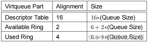
The Alignment column gives the minimum alignment for each part of the virtqueue.
The Size column gives the total number of bytes for each part of the virtqueue.
Queue Size corresponds to the maximum number of buffers in the virtqueue2 . Queue Size value is always a power of 2. The maximum Queue Size value is 32768. This value is specified in a bus-specific way.
When the driver wants to send a buffer to the device, it fills in a slot in the descriptor table (or chains several together), and writes the descriptor index into the available ring. It then notifies the device. When the device has finished a buffer, it writes the descriptor index into the used ring, and sends a used buffer notification.
7.1 Driver Requirements: Virtqueues
The driver MUST ensure that the physical address of the first byte of each virtqueue part is a multiple of the specified alignment value in the above table.
7.2 Legacy Interfaces: A Note on Virtqueue Layout
For Legacy Interfaces, several additional restrictions are placed on the virtqueue layout:
Each virtqueue occupies two or more physically-contiguous pages (usually defined as 4096 bytes, but de- pending on the transport; henceforth referred to as Queue Align) and consists of three parts:

The bus-specific Queue Size field controls the total number of bytes for the virtqueue. When using the legacy interface, the transitional driver MUST retrieve the Queue Size field from the device and MUST allocate the total number of bytes for the virtqueue according to the following formula (Queue Align given in qalign and Queue Size given in qsz):
#define ALIGN(x) (((x) + qalign) & ~qalign)
static inline unsigned virtq_size(unsigned int qsz)
{
	return ALIGN(sizeof(struct virtq_desc)*qsz + sizeof(u16)*(3 + qsz))
			+ ALIGN(sizeof(u16)*3 + sizeof(struct virtq_used_elem)*qsz);
}
This wastes some space with padding. When using the legacy interface, both transitional devices and drivers MUST use the following virtqueue layout structure to locate elements of the virtqueue:
struct virtq {
	// The actual descriptors (16 bytes each)
	struct virtq_desc desc[ Queue Size ];
	// A ring of available descriptor heads with free-running index.
	struct virtq_avail avail;
	// Padding to the next Queue Align boundary.
	u8 pad[ Padding ];

	// A ring of used descriptor heads with free-running index.
	struct virtq_used used;
};
7.3 Legacy Interfaces: A Note on Virtqueue Endianness
Note that when using the legacy interface, transitional devices and drivers MUST use the native endian of the guest as the endian of fields and in the virtqueue. This is opposed to little-endian for non-legacy interface as specified by this standard. It is assumed that the host is already aware of the guest endian.
7.4 Message Framing
The framing of messages with descriptors is independent of the contents of the buffers. For example, a network transmit buffer consists of a 12 byte header followed by the network packet. This could be most simply placed in the descriptor table as a 12 byte output descriptor followed by a 1514 byte output descriptor, but it could also consist of a single 1526 byte output descriptor in the case where the header and packet are adjacent, or even three or more descriptors (possibly with loss of efficiency in that case).
Note that, some device implementations have large-but-reasonable restrictions on total descriptor size (such as based on IOV_MAX in the host OS). This has not been a problem in practice: little sympathy will be given to drivers which create unreasonably-sized descriptors such as by dividing a network packet into 1500 single- byte descriptors!
7.4.1 Device Requirements: Message Framing
The device MUST NOT make assumptions about the particular arrangement of descriptors. The device MAY have a reasonable limit of descriptors it will allow in a chain.
7.4.2 Driver Requirements: Message Framing
The driver MUST place any device-writable descriptor elements after any device-readable descriptor ele- ments.
The driver SHOULD NOT use an excessive number of descriptors to describe a buffer.
7.4.3 Legacy Interface: Message Framing
Regrettably, initial driver implementations used simple layouts, and devices came to rely on it, despite this specification wording. In addition, the specification for virtio_blk SCSI commands required intuiting field lengths from frame boundaries (see 5.2.6.3 Legacy Interface: Device Operation)
Thus when using the legacy interface, the VIRTIO_F_ANY_LAYOUT feature indicates to both the device and the driver that no assumptions were made about framing. Requirements for transitional drivers when this is not negotiated are included in each device section.
7.5 The Virtqueue Descriptor Table
The descriptor table refers to the buffers the driver is using for the device. addr is a physical address, and the buffers can be chained via next. Each descriptor describes a buffer which is read-only for the device (“device-readable”) or write-only for the device (“device-writable”), but a chain of descriptors can contain both device-readable and device-writable buffers.
The actual contents of the memory offered to the device depends on the device type. Most common is to begin the data with a header (containing little-endian fields) for the device to read, and postfix it with a status tailer for the device to write.
struct virtq_desc {
	/* Address (guest-physical). */
	le64 addr;
	/* Length. */
	le32 len;
	/* This marks a buffer as continuing via the next field. */
	#define VIRTQ_DESC_F_NEXT   1
	/* This marks a buffer as device write-only (otherwise device read-only). */
	#define VIRTQ_DESC_F_WRITE     2
	/* This means the buffer contains a list of buffer descriptors. */
	#define VIRTQ_DESC_F_INDIRECT   4
	/* The flags as indicated above. */
	le16 flags;
	/* Next field if flags & NEXT */
	le16 next;
};
The number of descriptors in the table is defined by the queue size for this virtqueue: this is the maximum possible descriptor chain length.
If VIRTIO_F_IN_ORDER has been negotiated, driver uses descriptors in ring order: starting from offset 0 in the table, and wrapping around at the end of the table.
Note: The legacy [Virtio PCI Draft] referred to this structure as vring_desc, and the constants as VRING_-
DESC_F_NEXT, etc, but the layout and values were identical.
7.5.1 Device Requirements: The Virtqueue Descriptor Table
A device MUST NOT write to a device-readable buffer, and a device SHOULD NOT read a device-writable buffer (it MAY do so for debugging or diagnostic purposes). A device MUST NOT write to any descriptor table entry.
7.5.2 Driver Requirements: The Virtqueue Descriptor Table
Drivers MUST NOT add a descriptor chain longer than 232 bytes in total; this implies that loops in the descriptor chain are forbidden!
If VIRTIO_F_IN_ORDER has been negotiated, and when making a descriptor with VRING_DESC_F_NEXT set in flags at offset x in the table available to the device, driver MUST set next to 0 for the last descriptor in the table (where x = queue_size − 1) and to x + 1 for the rest of the descriptors.
7.5.3 Indirect Descriptors
Some devices benefit by concurrently dispatching a large number of large requests. The VIRTIO_F_INDI- RECT_DESC feature allows this (see Avirtio_queue.h). To increase ring capacity the driver can store a table of indirect descriptors anywhere in memory, and insert a descriptor in main virtqueue (with flags&VIRTQ_- DESC_F_INDIRECT on) that refers to memory buffer containing this indirect descriptor table; addr and len refer to the indirect table address and length in bytes, respectively.
The indirect table layout structure looks like this (len is the length of the descriptor that refers to this table, which is a variable, so this code won’t compile):
struct indirect_descriptor_table {
	/* The actual descriptors (16 bytes each) */
	struct virtq_desc desc[len / 16];
};
The first indirect descriptor is located at start of the indirect descriptor table (index 0), additional indirect descriptors are chained by next. An indirect descriptor without a valid next (with flags&VIRTQ_DESC_- F_NEXT off) signals the end of the descriptor. A single indirect descriptor table can include both device- readable and device-writable descriptors.
If VIRTIO_F_IN_ORDER has been negotiated, indirect descriptors use sequential indices, in-order: index 0 followed by index 1 followed by index 2, etc.
7.5.3.1 Driver Requirements: Indirect Descriptors
The driver MUST NOT set the VIRTQ_DESC_F_INDIRECT flag unless the VIRTIO_F_INDIRECT_DESC feature was negotiated. The driver MUST NOT set the VIRTQ_DESC_F_INDIRECT flag within an indirect descriptor (ie. only one table per descriptor).
A driver MUST NOT create a descriptor chain longer than the Queue Size of the device. A driver MUST NOT set both VIRTQ_DESC_F_INDIRECT and VIRTQ_DESC_F_NEXT in flags.
If VIRTIO_F_IN_ORDER has been negotiated, indirect descriptors MUST appear sequentially, with next taking the value of 1 for the 1st descriptor, 2 for the 2nd one, etc.
7.5.3.2 Device Requirements: Indirect Descriptors
The device MUST ignore the write-only flag (flags&VIRTQ_DESC_F_WRITE) in the descriptor that refers to an indirect table.
The device MUST handle the case of zero or more normal chained descriptors followed by a single descriptor with flags&VIRTQ_DESC_F_INDIRECT.
Note: While unusual (most implementations either create a chain solely using non-indirect descriptors, or use a single indirect element), such a layout is valid.
7.6 The Virtqueue Available Ring
The available ring has the following layout structure:
struct virtq_avail {
#define VIRTQ_AVAIL_F_NO_INTERRUPT
	le16 flags;
	le16 idx;
	le16 ring[ /* Queue Size */
	le16 used_event; /* Only if
};
The driver uses the available ring to offer buffers to the device: each ring entry refers to the head of a descriptor chain. It is only written by the driver and read by the device.
idx field indicates where the driver would put the next descriptor entry in the ring (modulo the queue size). This starts at 0, and increases.
Note: The legacy [Virtio PCI Draft] referred to this structure as vring_avail, and the constant as VRING_AVAIL_F_NO_INTERRUPT, but the layout and value were identical.
7.6.1 Driver Requirements: The Virtqueue Available Ring
A driver MUST NOT decrement the available idx on a virtqueue (ie. there is no way to “unexpose” buffers).
7.7 Used Buffer Notification Suppression
If the VIRTIO_F_EVENT_IDX feature bit is not negotiated, the flags field in the available ring offers a crude mechanism for the driver to inform the device that it doesn’t want notifications when buffers are used. Other- wise used_event is a more performant alternative where the driver specifies how far the device can progress before a notification is required.
Neither of these notification suppression methods are reliable, as they are not synchronized with the device, but they serve as useful optimizations.
7.7.1 Driver Requirements: Used Buffer Notification Suppression
If the VIRTIO_F_EVENT_IDX feature bit is not negotiated:
• The driver MUST set flags to 0 or 1.
• The driver MAY set flags to 1 to advise the device that notifications are not needed. Otherwise, if the VIRTIO_F_EVENT_IDX feature bit is negotiated:
• The driver MUST set flags to 0.
• The driver MAY use used_event to advise the device that notifications are unnecessary until the device writes an entry with an index specified by used_event into the used ring (equivalently, until idx in the
used ring will reach the value used_event + 1).
The driver MUST handle spurious notifications from the device.
7.7.2 Device Requirements: Used Buffer Notification Suppression
If the VIRTIO_F_EVENT_IDX feature bit is not negotiated:
• The device MUST ignore the used_event value.
• After the device writes a descriptor index into the used ring:
– If flags is 1, the device SHOULD NOT send a notification.
– If flags is 0, the device MUST send a notification.
Otherwise, if the VIRTIO_F_EVENT_IDX feature bit is negotiated:
• The device MUST ignore the lower bit of flags.
• After the device writes a descriptor index into the used ring:
– If the idx field in the used ring (which determined where that descriptor index was placed) was equal to used_event, the device MUST send a notification.
– Otherwise the device SHOULD NOT send a notification.
Note: For example, if used_event is 0, then a device using
VIRTIO_F_EVENT_IDX would send a used buffer notification to the driver after the first buffer is used (and again after the 65536th buffer, etc).
7.8 The Virtqueue Used Ring
The used ring has the following layout structure:
struct virtq_used {
#define VIRTQ_USED_F_NO_NOTIFY  1
	le16 flags;
	le16 idx;
	struct virtq_used_elem ring[ /* Queue Size */];
	le16 avail_event; /* Only if VIRTIO_F_EVENT_IDX */
};
/* le32 is used here for ids for padding reasons. */
struct virtq_used_elem {
	/* Index of start of used descriptor chain. */
	le32 id;
	/*
	* The number of bytes written into the device writable portion of
	* the buffer described by the descriptor chain.
	*/
	le32 len;
};
The used ring is where the device returns buffers once it is done with them: it is only written to by the device, and read by the driver.
Each entry in the ring is a pair: id indicates the head entry of the descriptor chain describing the buffer (this matches an entry placed in the available ring by the guest earlier), and len the total of bytes written into the buffer.
Note: len is particularly useful for drivers using untrusted buffers: if a driver does not know exactly how much has been written by the device, the driver would have to zero the buffer in advance to ensure no data leakage occurs.
For example, a network driver may hand a received buffer directly to an unprivileged userspace application. If the network device has not overwritten the bytes which were in that buffer, this could leak the contents of freed memory from other processes to the application.
idx field indicates where the device would put the next descriptor entry in the ring (modulo the queue size). This starts at 0, and increases.
Note: The legacy [Virtio PCI Draft] referred to these structures as vring_used and vring_used_elem, and
the constant as VRING_USED_F_NO_NOTIFY, but the layout and value were identical.
7.8.1 Legacy Interface: The Virtqueue Used Ring
Historically, many drivers ignored the len value, as a result, many devices set len incorrectly. Thus, when using the legacy interface, it is generally a good idea to ignore the len value in used ring entries if possible. Specific known issues are listed per device type.
7.8.2 Device Requirements: The Virtqueue Used Ring
The device MUST set len prior to updating the used idx.
The device MUST write at least len bytes to descriptor, beginning at the first device-writable buffer, prior to updating the used idx.
The device MAY write more than len bytes to descriptor.
Note: There are potential error cases where a device might not know what parts of the buffers have been written. This is why len is permitted to be an underestimate: that’s preferable to the driver believing that uninitialized memory has been overwritten when it has not.
7.8.3 Driver Requirements: The Virtqueue Used Ring
The driver MUST NOT make assumptions about data in device-writable buffers beyond the first len bytes, and SHOULD ignore this data.
7.9 In-order use of descriptors
Some devices always use descriptors in the same order in which they have been made available. These devices can offer the VIRTIO_F_IN_ORDER feature. If negotiated, this knowledge allows devices to notify the use of a batch of buffers to the driver by only writing out a single used ring entry with the id corresponding to the head entry of the descriptor chain describing the last buffer in the batch.
The device then skips forward in the ring according to the size of the batch. Accordingly, it increments the used idx by the size of the batch.
The driver needs to look up the used id and calculate the batch size to be able to advance to where the next used ring entry will be written by the device.
This will result in the used ring entry at an offset matching the first available ring entry in the batch, the used ring entry for the next batch at an offset matching the first available ring entry in the next batch, etc.
The skipped buffers (for which no used ring entry was written) are assumed to have been used (read or written) by the device completely.
7.10 Available Buffer Notification Suppression
The device can suppress available buffer notifications in a manner analogous to the way drivers can sup- press used buffer notifications as detailed in section 2.7.7. The device manipulates flags or avail_event in the used ring the same way the driver manipulates flags or used_event in the available ring.
7.10.1 Driver Requirements: Available Buffer Notification Suppression
The driver MUST initialize flags in the used ring to 0 when allocating the used ring.
If the VIRTIO_F_EVENT_IDX feature bit is not negotiated:
• The driver MUST ignore the avail_event value.
• After the driver writes a descriptor index into the available ring:
– If flags is 1, the driver SHOULD NOT send a notification.
– If flags is 0, the driver MUST send a notification.
Otherwise, if the VIRTIO_F_EVENT_IDX feature bit is negotiated:
• The driver MUST ignore the lower bit of flags.
• After the driver writes a descriptor index into the available ring:
– If the idx field in the available ring (which determined where that descriptor index was placed) was equal to avail_event, the driver MUST send a notification.
– Otherwise the driver SHOULD NOT send a notification.
7.10.2 Device Requirements: Available Buffer Notification Suppression
If the VIRTIO_F_EVENT_IDX feature bit is not negotiated:
• The device MUST set flags to 0 or 1.
• The device MAY set flags to 1 to advise the driver that notifications are not needed. Otherwise, if the VIRTIO_F_EVENT_IDX feature bit is negotiated:
• The device MUST set flags to 0.
• The device MAY use avail_event to advise the driver that notifications are unnecessary until the driver writes entry with an index specified by avail_event into the available ring (equivalently, until idx in the
available ring will reach the value avail_event + 1).
The device MUST handle spurious notifications from the driver.
7.11 Helpers for Operating Virtqueues
The Linux Kernel Source code contains the definitions above and helper routines in a more usable form, in include/uapi/linux/virtio_ring.h. This was explicitly licensed by IBM and Red Hat under the (3-clause) BSD license so that it can be freely used by all other projects, and is reproduced (with slight variation) in A virtio_queue.h.
7.12 Virtqueue Operation
There are two parts to virtqueue operation: supplying new available buffers to the device, and processing used buffers from the device.
Note: As an example, the simplest virtio network device has two virtqueues: the transmit virtqueue and the receive virtqueue. The driver adds outgoing (device-readable) packets to the transmit virtqueue, and then frees them after they are used. Similarly, incoming (device-writable) buffers are added to the receive virtqueue, and processed after they are used.
What follows is the requirements of each of these two parts when using the split virtqueue format in more detail.
7.13 Supplying Buffers to The Device
The driver offers buffers to one of the device’s virtqueues as follows:
- The driver places the buffer into free descriptor(s) in the descriptor table, chaining as necessary (see 2.7.5 The Virtqueue Descriptor Table).
- The driver places the index of the head of the descriptor chain into the next ring entry of the available ring.
- Steps 1 and 2 MAY be performed repeatedly if batching is possible.
- The driver performs a suitable memory barrier to ensure the device sees the updated descriptor table and available ring before the next step.
- The available idx is increased by the number of descriptor chain heads added to the available ring.
- The driver performs a suitable memory barrier to ensure that it updates the idx field before checking for notification suppression.
- The driver sends an available buffer notification to the device if such notifications are not suppressed.
Note that the above code does not take precautions against the available ring buffer wrapping around: this is not possible since the ring buffer is the same size as the descriptor table, so step (1) will prevent such a condition.
In addition, the maximum queue size is 32768 (the highest power of 2 which fits in 16 bits), so the 16-bit idx
value can always distinguish between a full and empty buffer.
What follows is the requirements of each stage in more detail.
7.13.1 Placing Buffers Into The Descriptor Table
A buffer consists of zero or more device-readable physically-contiguous elements followed by zero or more physically-contiguous device-writable elements (each has at least one element). This algorithm maps it into
the descriptor table to form a descriptor chain:
for each buffer element, b:
- Get the next free descriptor table entry, d
- Set d.addr to the physical address of the start of b
- Set d.len to the length of b.
- If b is device-writable, set d.flags to VIRTQ_DESC_F_WRITE, otherwise 0.
- If there is a buffer element after this:
(a) Set d.next to the index of the next free descriptor element.
(b) Set the VIRTQ_DESC_F_NEXT bit in d.flags.
In practice, d.next is usually used to chain free descriptors, and a separate count kept to check there are enough free descriptors before beginning the mappings.
7.13.2 Updating The Available Ring
The descriptor chain head is the first d in the algorithm above, ie. the index of the descriptor table entry re- ferring to the first part of the buffer. A naive driver implementation MAY do the following (with the appropriate conversion to-and-from little-endian assumed):
avail->ring[avail->idx % qsz] = head;
However, in general the driver MAY add many descriptor chains before it updates idx (at which point they become visible to the device), so it is common to keep a counter of how many the driver has added:
avail->ring[(avail->idx + added++) % qsz] = head;
7.13.3 Updating idx
idx always increments, and wraps naturally at 65536:
avail->idx += added;
Once available idx is updated by the driver, this exposes the descriptor and its contents. The device MAY access the descriptor chains the driver created and the memory they refer to immediately.
7.13.3.1 Driver Requirements: Updating idx
The driver MUST perform a suitable memory barrier before the idx update, to ensure the device sees the most up-to-date copy.
7.13.4 Notifying The Device
The actual method of device notification is bus-specific, but generally it can be expensive. So the device MAY suppress such notifications if it doesn’t need them, as detailed in section 2.7.10.
The driver has to be careful to expose the new idx value before checking if notifications are suppressed.
7.13.4.1 Driver Requirements: Notifying The Device
The driver MUST perform a suitable memory barrier before reading flags or avail_event, to avoid missing a notification.
7.14 Receiving Used Buffers From The Device
Once the device has used buffers referred to by a descriptor (read from or written to them, or parts of both, depending on the nature of the virtqueue and the device), it sends a used buffer notification to the driver as detailed in section 2.7.7.
Note: For optimal performance, a driver MAY disable used buffer notifications while processing the used ring, but beware the problem of missing notifications between emptying the ring and reenabling no- tifications. This is usually handled by re-checking for more used buffers after notifications are re-enabled:
virtq_disable_used_buffer_notifications(vq);

for (;;) {
	if (vq->last_seen_used != le16_to_cpu(virtq->used.idx)) {
		virtq_enable_used_buffer_notifications(vq);
		mb();
		if (vq->last_seen_used != le16_to_cpu(virtq->used.idx))
			break;
		virtq_disable_used_buffer_notifications(vq);
	}
	struct virtq_used_elem *e = virtq.used->ring[vq->last_seen_used%vsz];
	process_buffer(e);
	vq->last_seen_used++;
}
8 Packed Virtqueues
Packed virtqueues is an alternative compact virtqueue layout using read-write memory, that is memory that is both read and written by both host and guest.
Use of packed virtqueues is negotiated by the VIRTIO_F_RING_PACKED feature bit.
Packed virtqueues support up to 215 entries each.
With current transports, virtqueues are located in guest memory allocated by the driver. Each packed virtqueue consists of three parts:
• Descriptor Ring - occupies the Descriptor Area
• Driver Event Suppression - occupies the Driver Area
• Device Event Suppression - occupies the Device Area
Where the Descriptor Ring in turn consists of descriptors, and where each descriptor can contain the fol- lowing parts:
• Buffer ID
• Element Address
• Element Length
• Flags
A buffer consists of zero or more device-readable physically-contiguous elements followed by zero or more physically-contiguous device-writable elements (each buffer has at least one element).
When the driver wants to send such a buffer to the device, it writes at least one available descriptor describing elements of the buffer into the Descriptor Ring. The descriptor(s) are associated with a buffer by means of a Buffer ID stored within the descriptor.
The driver then notifies the device. When the device has finished processing the buffer, it writes a used device descriptor including the Buffer ID into the Descriptor Ring (overwriting a driver descriptor previously made available), and sends a used event notification.
The Descriptor Ring is used in a circular manner: the driver writes descriptors into the ring in order. After reaching the end of the ring, the next descriptor is placed at the head of the ring. Once the ring is full of driver descriptors, the driver stops sending new requests and waits for the device to start processing descriptors and to write out some used descriptors before making new driver descriptors available.
Similarly, the device reads descriptors from the ring in order and detects that a driver descriptor has been made available. As processing of descriptors is completed, used descriptors are written by the device back into the ring.
Note: after reading driver descriptors and starting their processing in order, the device might complete their processing out of order. Used device descriptors are written in the order in which their processing is complete.
The Device Event Suppression data structure is write-only by the device. It includes information for reducing the number of device events, i.e., sending fewer available buffer notifications to the device.
The Driver Event Suppression data structure is read-only by the device. It includes information for reducing the number of driver events, i.e., sending fewer used buffer notifications to the driver.
8.1 Driver and Device Ring Wrap Counters
Each of the driver and the device are expected to maintain, internally, a single-bit ring wrap counter initialized to 1.
The counter maintained by the driver is called the Driver Ring Wrap Counter. The driver changes the value of this counter each time it makes available the last descriptor in the ring (after making the last descriptor available).
The counter maintained by the device is called the Device Ring Wrap Counter. The device changes the value of this counter each time it uses the last descriptor in the ring (after marking the last descriptor used).
It is easy to see that the Driver Ring Wrap Counter in the driver matches the Device Ring Wrap Counter in the device when both are processing the same descriptor, or when all available descriptors have been used.
To mark a descriptor as available and used, both the driver and the device use the following two flags:
#define VIRTQ_DESC_F_AVAIL (1 << 7)
#define VIRTQ_DESC_F_USED (1 << 15)
To mark a descriptor as available, the driver sets the VIRTQ_DESC_F_AVAIL bit in Flags to match the internal Driver Ring Wrap Counter. It also sets the VIRTQ_DESC_F_USED bit to match the inverse value (i.e. to not match the internal Driver Ring Wrap Counter).
To mark a descriptor as used, the device sets the VIRTQ_DESC_F_USED bit in Flags to match the internal Device Ring Wrap Counter. It also sets the VIRTQ_DESC_F_AVAIL bit to match the same value.
Thus VIRTQ_DESC_F_AVAIL and VIRTQ_DESC_F_USED bits are different for an available descriptor and equal for a used descriptor.
Note that this observation is mostly useful for sanity-checking as these are necessary but not sufficient conditions - for example, all descriptors are zero-initialized. To detect used and available descriptors it is possible for drivers and devices to keep track of the last observed value of VIRTQ_DESC_F_USED/VIRTQ_- DESC_F_AVAIL. Other techniques to detect VIRTQ_DESC_F_AVAIL/VIRTQ_DESC_F_USED bit changes might also be possible.
8.2 Polling of available and used descriptors
Writes of device and driver descriptors can generally be reordered, but each side (driver and device) are only required to poll (or test) a single location in memory: the next device descriptor after the one they processed previously, in circular order.
Sometimes the device needs to only write out a single used descriptor after processing a batch of multiple available descriptors. As described in more detail below, this can happen when using descriptor chaining or with in-order use of descriptors. In this case, the device writes out a used descriptor with the buffer id of the last descriptor in the group. After processing the used descriptor, both device and driver then skip forward in the ring the number of the remaining descriptors in the group until processing (reading for the driver and writing for the device) the next used descriptor.
8.3 Write Flag
In an available descriptor, the VIRTQ_DESC_F_WRITE bit within Flags is used to mark a descriptor as corresponding to a write-only or read-only element of a buffer.
/* This marks a descriptor as device write-only (otherwise device read-only). */
#define VIRTQ_DESC_F_WRITE 2
In a used descriptor, this bit is used to specify whether any data has been written by the device into any parts of the buffer.
8.4 Element Address and Length
In an available descriptor, Element Address corresponds to the physical address of the buffer element. The length of the element assumed to be physically contiguous is stored in Element Length.
In a used descriptor, Element Address is unused. Element Length specifies the length of the buffer that has been initialized (written to) by the device.
Element Length is reserved for used descriptors without the VIRTQ_DESC_F_WRITE flag, and is ignored by drivers.
8.5 Scatter-Gather Support
Some drivers need an ability to supply a list of multiple buffer elements (also known as a scatter/gather list) with a request. Two features support this: descriptor chaining and indirect descriptors.
If neither feature is in use by the driver, each buffer is physically-contiguous, either read-only or write-only and is described completely by a single descriptor.
While unusual (most implementations either create all lists solely using non-indirect descriptors, or always use a single indirect element), if both features have been negotiated, mixing indirect and non-indirect de- scriptors in a ring is valid, as long as each list only contains descriptors of a given type.
Scatter/gather lists only apply to available descriptors. A single used descriptor corresponds to the whole list.
The device limits the number of descriptors in a list through a transport-specific and/or device-specific value. If not limited, the maximum number of descriptors in a list is the virt queue size.
8.6 Next Flag: Descriptor Chaining
The packed ring format allows the driver to supply a scatter/gather list to the device by using multiple de- scriptors, and setting the VIRTQ_DESC_F_NEXT bit in Flags for all but the last available descriptor.
/* This marks a buffer as continuing. */
#define VIRTQ_DESC_F_NEXT   1
Buffer ID is included in the last descriptor in the list.
The driver always makes the first descriptor in the list available after the rest of the list has been written out into the ring. This guarantees that the device will never observe a partial scatter/gather list in the ring.
Note: all flags, including VIRTQ_DESC_F_AVAIL, VIRTQ_DESC_F_USED, VIRTQ_DESC_F_WRITE must be set/cleared correctly in all descriptors in the list, not just the first one.
The device only writes out a single used descriptor for the whole list. It then skips forward according to the number of descriptors in the list. The driver needs to keep track of the size of the list corresponding to each buffer ID, to be able to skip to where the next used descriptor is written by the device.
For example, if descriptors are used in the same order in which they are made available, this will result in the used descriptor overwriting the first available descriptor in the list, the used descriptor for the next list overwriting the first available descriptor in the next list, etc.
VIRTQ_DESC_F_NEXT is reserved in used descriptors, and should be ignored by drivers.
8.7 Indirect Flag: Scatter-Gather Support
Some devices benefit by concurrently dispatching a large number of large requests. The VIRTIO_F_INDI- RECT_DESC feature allows this. To increase ring capacity the driver can store a (read-only by the device) table of indirect descriptors anywhere in memory, and insert a descriptor in the main virtqueue (with Flags bit VIRTQ_DESC_F_INDIRECT on) that refers to a buffer element containing this indirect descriptor table; addr and len refer to the indirect table address and length in bytes, respectively.
/* This means the element contains a table of descriptors. */
#define VIRTQ_DESC_F_INDIRECT   4
The indirect table layout structure looks like this (len is the Buffer Length of the descriptor that refers to this table, which is a variable):
struct pvirtq_indirect_descriptor_table {
	/* The actual descriptor structures (struct pvirtq_desc each) */
	struct pvirtq_desc desc[len / sizeof(struct pvirtq_desc)];
};
The first descriptor is located at the start of the indirect descriptor table, additional indirect descriptors come immediately afterwards. The VIRTQ_DESC_F_WRITE flags bit is the only valid flag for descriptors in the indirect table. Others are reserved and are ignored by the device. Buffer ID is also reserved and is ignored by the device.
In descriptors with VIRTQ_DESC_F_INDIRECT set VIRTQ_DESC_F_WRITE is reserved and is ignored by the device.
2.8.8 In-order use of descriptors
Some devices always use descriptors in the same order in which they have been made available. These devices can offer the VIRTIO_F_IN_ORDER feature. If negotiated, this knowledge allows devices to notify the use of a batch of buffers to the driver by only writing out a single used descriptor with the Buffer ID corresponding to the last descriptor in the batch.
The device then skips forward in the ring according to the size of the batch. The driver needs to look up the used Buffer ID and calculate the batch size to be able to advance to where the next used descriptor will be written by the device.
This will result in the used descriptor overwriting the first available descriptor in the batch, the used descriptor for the next batch overwriting the first available descriptor in the next batch, etc.
The skipped buffers (for which no used descriptor was written) are assumed to have been used (read or written) by the device completely.
2.8.9 Multi-buffer requests
Some devices combine multiple buffers as part of processing of a single request. These devices always mark the descriptor corresponding to the first buffer in the request used after the rest of the descriptors (corresponding to rest of the buffers) in the request - which follow the first descriptor in ring order - has been marked used and written out into the ring. This guarantees that the driver will never observe a partial request in the ring.
2.8.10 Driver and Device Event Suppression
In many systems used and available buffer notifications involve significant overhead. To mitigate this over- head, each virtqueue includes two identical structures used for controlling notifications between the device and the driver.
The Driver Event Suppression structure is read-only by the device and controls the used buffer notifications sent by the device to the driver.
The Device Event Suppression structure is read-only by the driver and controls the available buffer notifica- tions sent by the driver to the device.
Each of these Event Suppression structures includes the following fields:
Descriptor Ring Change Event Flags Takes values:
/* Enable events */
#define RING_EVENT_FLAGS_ENABLE 0x0
/* Disable events */
#define RING_EVENT_FLAGS_DISABLE 0x1
/*
* Enable events for a specific descriptor
* (as specified by Descriptor Ring Change Event Offset/Wrap Counter).
* Only valid if VIRTIO_F_EVENT_IDX has been negotiated.
*/
#define RING_EVENT_FLAGS_DESC 0x2
/* The value 0x3 is reserved */
Descriptor Ring Change Event Offset If Event Flags set to descriptor specific event: offset within the ring (in units of descriptor size). Event will only trigger when this descriptor is made available/used respectively.
Descriptor Ring Change Event Wrap Counter If Event Flags set to descriptor specific event: offset within the ring (in units of descriptor size). Event will only trigger when Ring Wrap Counter matches this value and a descriptor is made available/used respectively.
After writing out some descriptors, both the device and the driver are expected to consult the relevant struc- ture to find out whether a used respectively an available buffer notification should be sent.
8.10.1 Structure Size and Alignment
Each part of the virtqueue is physically-contiguous in guest memory, and has different alignment requirements.
The memory alignment and size requirements, in bytes, of each part of the virtqueue are summarized in the following table:
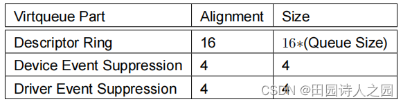
The Alignment column gives the minimum alignment for each part of the virtqueue.
The Size column gives the total number of bytes for each part of the virtqueue.
Queue Size corresponds to the maximum number of descriptors in the virtqueue3 . The Queue Size value does not have to be a power of 2.
8.11 Driver Requirements: Virtqueues
The driver MUST ensure that the physical address of the first byte of each virtqueue part is a multiple of the specified alignment value in the above table.
8.12 Device Requirements: Virtqueues
The device MUST start processing driver descriptors in the order in which they appear in the ring. The device MUST start writing device descriptors into the ring in the order in which they complete. The device MAY reorder descriptor writes once they are started.
8.13 The Virtqueue Descriptor Format
The available descriptor refers to the buffers the driver is sending to the device. addr is a physical address, and the descriptor is identified with a buffer using the id field.
struct pvirtq_desc {
	/* Buffer Address. */
	le64 addr;
	/* Buffer Length. */
	le32 len;
	/* Buffer ID. */
	le16 id;
	/* The flags depending on descriptor type. */
	le16 flags;
}
The descriptor ring is zero-initialized.
8.14 Event Suppression Structure Format
The following structure is used to reduce the number of notifications sent between driver and device.
struct pvirtq_event_suppress {
	le16 {
		desc_event_off : 15; /* Descriptor Ring Change Event Offset */
		desc_event_wrap : 1; /* Descriptor Ring Change Event Wrap Counter */
	} desc; /* If desc_event_flags set to RING_EVENT_FLAGS_DESC */
	le16 {
		desc_event_flags : 2, /* Descriptor Ring Change Event Flags */
		reserved : 14; /* Reserved, set to 0 */
	} flags;
};
8.15 Device Requirements: The Virtqueue Descriptor Table
A device MUST NOT write to a device-readable buffer, and a device SHOULD NOT read a device-writable buffer. A device MUST NOT use a descriptor unless it observes the VIRTQ_DESC_F_AVAIL bit in its flags being changed (e.g. as compared to the initial zero value). A device MUST NOT change a descriptor after changing it’s the VIRTQ_DESC_F_USED bit in its flags.
8.16 Driver Requirements: The Virtqueue Descriptor Table
A driver MUST NOT change a descriptor unless it observes the VIRTQ_DESC_F_USED bit in its flags being changed. A driver MUST NOT change a descriptor after changing the VIRTQ_DESC_F_AVAIL bit in its flags. When notifying the device, driver MUST set next_off and next_wrap to match the next descriptor not yet made available to the device. A driver MAY send multiple available buffer notifications without making any new descriptors available to the device.
8.17 Driver Requirements: Scatter-Gather Support
A driver MUST NOT create a descriptor list longer than allowed by the device.
A driver MUST NOT create a descriptor list longer than the Queue Size.
This implies that loops in the descriptor list are forbidden!
The driver MUST place any device-writable descriptor elements after any device-readable descriptor ele- ments.
A driver MUST NOT depend on the device to use more descriptors to be able to write out all descriptors in a list. A driver MUST make sure there’s enough space in the ring for the whole list before making the first descriptor in the list available to the device.
A driver MUST NOT make the first descriptor in the list available before all subsequent descriptors compris- ing the list are made available.
8.18 Device Requirements: Scatter-Gather Support
The device MUST use descriptors in a list chained by the VIRTQ_DESC_F_NEXT flag in the same order that they were made available by the driver.
The device MAY limit the number of buffers it will allow in a list.
8.19 Driver Requirements: Indirect Descriptors
The driver MUST NOT set the VIRTQ_DESC_F_INDIRECT flag unless the VIRTIO_F_INDIRECT_DESC feature was negotiated. The driver MUST NOT set any flags except DESC_F_WRITE within an indirect descriptor.
A driver MUST NOT create a descriptor chain longer than allowed by the device.
A driver MUST NOT write direct descriptors with VIRTQ_DESC_F_INDIRECT set in a scatter-gather list linked by VIRTQ_DESC_F_NEXT. flags.
8.20 Virtqueue Operation
There are two parts to virtqueue operation: supplying new available buffers to the device, and processing used buffers from the device.
What follows is the requirements of each of these two parts when using the packed virtqueue format in more detail.
8.21 Supplying Buffers to The Device
The driver offers buffers to one of the device’s virtqueues as follows:
- The driver places the buffer into free descriptor(s) in the Descriptor Ring.
- The driver performs a suitable memory barrier to ensure that it updates the descriptor(s) before check- ing for notification suppression.
- If notifications are not suppressed, the driver notifies the device of the new available buffers.
What follows are the requirements of each stage in more detail.
8.21.1 Placing Available Buffers Into The Descriptor Ring
For each buffer element, b:
- Get the next descriptor table entry, d
- Get the next free buffer id value
- Set d.addr to the physical address of the start of b
- Set d.len to the length of b.
- Set d.id to the buffer id
- Calculate the flags as follows:
(a) If b is device-writable, set the VIRTQ_DESC_F_WRITE bit to 1, otherwise 0
(b) Set the VIRTQ_DESC_F_AVAIL bit to the current value of the Driver Ring Wrap Counter © Set the VIRTQ_DESC_F_USED bit to inverse value - Perform a memory barrier to ensure that the descriptor has been initialized
- Set d.flags to the calculated flags value
- If d is the last descriptor in the ring, toggle the Driver Ring Wrap Counter
- Otherwise, increment d to point at the next descriptor
This makes a single descriptor buffer available. However, in general the driver MAY make use of a batch of descriptors as part of a single request. In that case, it defers updating the descriptor flags for the first descriptor (and the previous memory barrier) until after the rest of the descriptors have been initialized.
Once the descriptor flags field is updated by the driver, this exposes the descriptor and its contents. The device MAY access the descriptor and any following descriptors the driver created and the memory they refer to immediately.
8.21.1.1 Driver Requirements: Updating flags
The driver MUST perform a suitable memory barrier before the flags update, to ensure the device sees the most up-to-date copy.
8.21.2 Sending Available Buffer Notifications
The actual method of device notification is bus-specific, but generally it can be expensive. So the device MAY suppress such notifications if it doesn’t need them, using the Event Suppression structure comprising the Device Area as detailed in section 2.8.14.
The driver has to be careful to expose the new flags value before checking if notifications are suppressed.
8.21.3 Implementation Example
Below is a driver code example. It does not attempt to reduce the number of available buffer notifications, neither does it support the VIRTIO_F_EVENT_IDX feature.
/* Note: vq->avail_wrap_count is initialized to 1 */
/* Note: vq->sgs is an array same size as the ring */

id = alloc_id(vq);

first = vq->next_avail;
sgs = 0;

for (each buffer element b) {
	sgs++;

	vq->ids[vq->next_avail] = -1;
	vq->desc[vq->next_avail].address = get_addr(b);
	vq->desc[vq->next_avail].len = get_len(b);

	avail = vq->avail_wrap_count ? VIRTQ_DESC_F_AVAIL : 0;
			used = !vq->avail_wrap_count ? VIRTQ_DESC_F_USED : 0;
	f = get_flags(b) | avail | used;
	if (b is not the last buffer element) {
					f |= VIRTQ_DESC_F_NEXT;
	}

	/* Don't mark the 1st descriptor available until all of them are ready. */
	if (vq->next_avail == first) {
		flags = f;
	} else {
		vq->desc[vq->next_avail].flags = f;
	}

	last = vq->next_avail;

	vq->next_avail++;

	if (vq->next_avail >= vq->size) {
		vq->next_avail = 0;
		vq->avail_wrap_count ^= 1;
	}
}

vq->sgs[id] = sgs;

/* ID included in the last descriptor in the list */
vq->desc[last].id = id;
write_memory_barrier();
vq->desc[first].flags = flags;

memory_barrier();

if (vq->device_event.flags != RING_EVENT_FLAGS_DISABLE) {
		notify_device(vq);
}
8.21.3.1 Driver Requirements: Sending Available Buffer Notifications
The driver MUST perform a suitable memory barrier before reading the Event Suppression structure occu- pying the Device Area. Failing to do so could result in mandatory available buffer notifications not being sent.
8.22 Receiving Used Buffers From The Device
Once the device has used buffers referred to by a descriptor (read from or written to them, or parts of both, depending on the nature of the virtqueue and the device), it sends a used buffer notification to the driver as detailed in section 2.8.14.
Note: For optimal performance, a driver MAY disable used buffer notifications while processing the used buffers, but beware the problem of missing notifications between emptying the ring and reenabling used buffer notifications. This is usually handled by re-checking for more used buffers after notifications are re-enabled:
/* Note: vq->used_wrap_count is initialized to 1 */

vq->driver_event.flags = RING_EVENT_FLAGS_DISABLE;

for (;;) {
	struct pvirtq_desc *d = vq->desc[vq->next_used];

	/*
	* Check that
	* 1. Descriptor has been made available. This check is necessary
	*    if the driver is making new descriptors available in parallel
	*    with this processing of used descriptors (e.g. from another thread).
	*    Note: there are many other ways to check this, e.g.
	*    track the number of outstanding available descriptors or buffers
	*    and check that it's not 0.
	* 2. Descriptor has been used by the device. */
	flags = d->flags;
	bool avail = flags & VIRTQ_DESC_F_AVAIL;
	bool used = flags & VIRTQ_DESC_F_USED;
	if (avail != vq->used_wrap_count | | used != vq->used_wrap_count) {
		vq->driver_event.flags = RING_EVENT_FLAGS_ENABLE;
		memory_barrier();

		/*
		* Re-test in case the driver made more descriptors available in
		* parallel with the used descriptor processing (e.g. from another
		* thread) and/or the device used more descriptors before the driver
		* enabled events.
		*/
		flags = d->flags;
		bool avail = flags & VIRTQ_DESC_F_AVAIL;
		bool used = flags & VIRTQ_DESC_F_USED;
		if (avail != vq->used_wrap_count | | used != vq->used_wrap_count) {
			break;
		}

		vq->driver_event.flags = RING_EVENT_FLAGS_DISABLE;
	}

	read_memory_barrier();

	/* skip descriptors until the next buffer */
	id = d->id;
	assert(id < vq->size);
	sgs = vq->sgs[id];
	vq->next_used += sgs;
	if (vq->next_used >= vq->size) {
		vq->next_used -= vq->size;
		vq->used_wrap_count ^= 1;
	}

	free_id(vq, id);

	process_buffer(d);
}


 1000
1000

 被折叠的 条评论
为什么被折叠?
被折叠的 条评论
为什么被折叠?
 到【灌水乐园】发言


