


 本文详细介绍了 Virtio-over-PCI 的规范,包括设备发现、配置布局及功能,探讨了 PCI 设备如何实现 Virtio 接口,并讨论了与驱动交互的具体要求。
Virtio Over PCI Bus
- 1 Virtio Over PCI Bus
- 1.1 Device Requirements: Virtio Over PCI Bus
- 1.2 PCI Device Discovery
- 1.3 PCI Device Layout
- 1.4 Virtio Structure PCI Capabilities
- 1.4.1 Driver Requirements: Virtio Structure PCI Capabilities
- 1.4.2 Device Requirements: Virtio Structure PCI Capabilities
- 1.4.3 Common configuration structure layout
- 1.4.4 Notification structure layout
- 1.4.5 ISR status capability
- 1.4.6 Device-specific configuration
- 1.4.7 Shared memory capability
- 1.4.8 Vendor data capability
- 1.4.9 PCI configuration access capability
- 1.4.10 Legacy Interfaces: A Note on PCI Device Layout
- 1.4.11 Non-transitional Device With Legacy Driver: A Note on PCI Device Layout
- 1.5 PCI-specific Initialization And Device Operation
基于virtio-1.2的官方文档去做的翻译
Virtio can use various different buses, thus the standard is split into virtio general and bus-specific sections.
Virtio可以使用各种不同的总线,因此标准被分为Virtio通用部分和总线特定的部分。
1 Virtio Over PCI Bus
Virtio devices are commonly implemented as PCI devices.
A Virtio device can be implemented as any kind of PCI device: a Conventional PCI device or a PCI Express device. To assure designs meet the latest level requirements, see the PCI-SIG home page at http://www.pcisig.com for any approved changes.
Virtio设备通常被实现为PCI设备。Virtio设备可以实现为任何类型的PCI设备:传统的PCI设备或PCI Express设备。为了确保设计满足最新级别的要求,请参见PCI-SIG主页 http://www.pcisig.com 确认任何已批准的更改。
1.1 Device Requirements: Virtio Over PCI Bus
A Virtio device using Virtio Over PCI Bus MUST expose to guest an interface that meets the specification requirements of the appropriate PCI specification: [PCI] and [PCIe] respectively.
使用Virtio Over PCI总线的Virtio设备必须向guest公开一个满足适当PCI规范要求的接口:[PCI]和[PCIe]。
1.2 PCI Device Discovery
Any PCI device with PCI Vendor ID 0x1AF4, and PCI Device ID 0x1000 through 0x107F inclusive is a virtio device. The actual value within this range indicates which virtio device is supported by the device. The PCI Device ID is calculated by adding 0x1040 to the Virtio Device ID, as indicated in section 5. Additionally, devices MAY utilize a Transitional PCI Device ID range, 0x1000 to 0x103F depending on the device type.
任何具有PCI 厂商ID 0x1AF4和PCI设备ID 0x1000到0x107F的PCI设备都是virtio设备。在此范围内的实际值表示该设备支持哪个virtio设备。PCI设备ID是通过将0x添加到Virtio设备ID1040来计算的,如第5节所示。此外,设备可以利用传统的PCI设备ID范围,0x1000到0x103F,根据设备类型的不同。
1.2.1 Device Requirements: PCI Device Discovery
Devices MUST have the PCI Vendor ID 0x1AF4. Devices MUST either have the PCI Device ID calculated by adding 0x1040 to the Virtio Device ID, as indicated in section 5 or have the Transitional PCI Device ID depending on the device type, as follows:
设备必须具有PCI供应商ID为0x1AF4。设备必须具有通过向Virtio设备ID添加0x1040来计算出的PCI设备ID,如第5节所示,或者根据设备类型具有传统的PCI设备ID,如下所示:
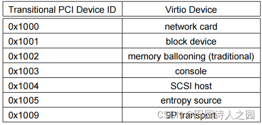
For example, the network card device with the Virtio Device ID 1 has the PCI Device ID 0x1041 or the Transitional PCI Device ID 0x1000.
例如,具有Virtio设备ID 1的网卡设备具有PCI设备ID 0x1041或传统PCI设备ID 0x1000。
The PCI Subsystem Vendor ID and the PCI Subsystem Device ID MAY reflect the PCI Vendor and Device ID of the environment (for informational purposes by the driver).
PCI子系统供应商ID和PCI子系统设备ID可以反映环境的PCI供应商和设备ID(供驱动程序参考)。
Non-transitional devices SHOULD have a PCI Device ID in the range 0x1040 to 0x107f. Non-transitional devices SHOULD have a PCI Revision ID of 1 or higher. Non-transitional devices SHOULD have a PCI Subsystem Device ID of 0x40 or higher.
非传统设备的PCI设备ID范围应为0x1040至0x107f。非传统设备的PCI版本ID应为1或更高。非传统性设备的PCI子系统设备ID应为0x40或更高。
This is to reduce the chance of a legacy driver attempting to drive the device.
这是为了减少遗留驱动程序试图驱动该设备的机会。
1.2.2 Driver Requirements: PCI Device Discovery
Drivers MUST match devices with the PCI Vendor ID 0x1AF4 and the PCI Device ID in the range 0x1040 to 0x107f, calculated by adding 0x1040 to the Virtio Device ID, as indicated in section 5. Drivers for device types listed in section 4.1.2 MUST match devices with the PCI Vendor ID 0x1AF4 and the Transitional PCI Device ID indicated in section 4.1.2.
驱动程序必须将设备与PCI供应商ID 0x1AF4和PCI设备ID在0x1040到0x107f之间,通过向Virtio设备ID添加0x1040计算,如第5节所示。第4.1.2节中列出的设备类型的驱动程序必须与PCI供应商ID 0x1AF4和第4.1.2节中显示的传统PCI设备ID匹配设备。
Drivers MUST match any PCI Revision ID value. Drivers MAY match any PCI Subsystem Vendor ID and any PCI Subsystem Device ID value.
驱动程序必须匹配任何PCI修订的ID值。驱动程序可以匹配任何PCI子系统供应商ID和任何PCI子系统设备ID值。
1.2.3 Legacy Interfaces: A Note on PCI Device Discovery
Transitional devices MUST have a PCI Revision ID of 0. Transitional devices MUST have the PCI Subsystem Device ID matching the Virtio Device ID, as indicated in section 5. Transitional devices MUST have the Transitional PCI Device ID in the range 0x1000 to 0x103f.
传统设备的PCI版本ID必须为0。传统设备必须具有与Virtio设备ID相匹配的PCI子系统设备ID,如第5节所示。传统设备必须具有在 0x1000 至 0x103f 范围内的传统 PCI 设备ID。
This is to match legacy drivers.
这是为了匹配遗留的驱动程序。
1.3 PCI Device Layout
The device is configured via I/O and/or memory regions (though see 4.1.4.9 for access via the PCI configuration space), as specified by Virtio Structure PCI Capabilities.
设备通过I/O和/或内存区域进行配置(尽管如4.1.4.9所示是通过PCI配置区域进行访问),由Virtio数据结构PCI功能指定)。
Fields of different sizes are present in the device configuration regions. All 64-bit, 32-bit and 16-bit fields are little-endian. 64-bit fields are to be treated as two 32-bit fields, with low 32 bit part followed by the high 32 bit part.
在设备配置区域中存在不同大小的字段。所有64位、32位和16位字段都是小的。64位字段将被视为两个32位字段,其中包括低32位部分和高32位部分。
1.3.1 Driver Requirements: PCI Device Layout
For device configuration access, the driver MUST use 8-bit wide accesses for 8-bit wide fields, 16-bit wide and aligned accesses for 16-bit wide fields and 32-bit wide and aligned accesses for 32-bit and 64-bit wide fields. For 64-bit fields, the driver MAY access each of the high and low 32-bit parts of the field independently.
对于设备配置访问,驱动程序必须对8位宽字段使用8位宽访问,对于16位宽字段使用16位宽和对齐访问,对于32位和64位宽字段使用32位宽和对齐访问。对于64位字段,驱动程序可以独立地访问该字段的每个高、低32位部分。
1.3.2 Device Requirements: PCI Device Layout
For 64-bit device configuration fields, the device MUST allow driver independent access to high and low 32-bit parts of the field.
对于64位设备配置字段,设备必须允许驱动程序独立访问字段的高和低32位部分。
1.4 Virtio Structure PCI Capabilities
The virtio device configuration layout includes several structures:
virtio设备的配置布局包括以下几种结构:
• Common configuration 通用配置
• Notifications 通知
• ISR Status ISR状态
• Device-specific configuration (optional) 设备特定的配置(可选)
• PCI configuration access PCI配置访问
Each structure can be mapped by a Base Address register (BAR) belonging to the function, or accessed via the special VIRTIO_PCI_CAP_PCI_CFG field in the PCI configuration space.
每个结构都可以通过属于该函数的基本地址寄存器(BAR)进行映射,也可以通过PCI配置空间中的特殊VIRTIO_PCI_CAP_PCI_CFG 字段进行访问。
The location of each structure is specified using a vendor-specific PCI capability located on the capability list in PCI configuration space of the device. This virtio structure capability uses little-endian format; all fields are read-only for the driver unless stated otherwise:
每个结构的位置都是使用位于设备的PCI配置空间中的功能列表中的一个特定于供应商的PCI功能来指定的。这种virtio结构功能使用小端格式;除非另有说明,所有字段都对驱动程序是只读的:
struct virtio_pci_cap {
	u8 cap_vndr; /* Generic PCI field: PCI_CAP_ID_VNDR */
	u8 cap_next; /* Generic PCI field: next ptr. */
	u8 cap_len; /* Generic PCI field: capability length */
	u8 cfg_type; /* Identifies the structure. */
	u8 bar; /* Where to find it. */
	u8 id; /* Multiple capabilities of the same type */
	u8 padding[2]; /* Pad to full dword. */
	le32 offset; /* Offset within bar. */
	le32 length; /* Length of the structure, in bytes. */
};
This structure can be followed by extra data, depending on cfg_type, as documented below.
这个结构之后可以有额外的数据,这取决于cfg_type,如下所示。
The fields are interpreted as follows:
这些字段的解释如下:
- cap_vndr 0x09; Identifies a vendor-specific capability.
- cap_vndr 0x09; 标识特定于供应商的功能。
- cap_next Link to next capability in the capability list in the PCI configuration space.
- cap_next链接到PCI配置空间中的功能列表中的下一个功能
- cap_len Length of this capability structure, including the whole of struct virtio_pci_cap, and extra data if any. This length MAY include padding, or fields unused by the driver.
- cap_len这个功能结构的长度,包括整个结构virtio_pci_cap,如果有的话,还有额外的数据。此长度可能包括填充,或驱动程序未使用的字段。
- cfg_type identifies the structure, according to the following table:
- cfg_type根据下表标识了该结构:
/* Common configuration */
#define VIRTIO_PCI_CAP_COMMON_CFG 1
/* Notifications */
#define VIRTIO_PCI_CAP_NOTIFY_CFG 2
/* ISR Status */
#define VIRTIO_PCI_CAP_ISR_CFG 3
/* Device specific configuration */
#define VIRTIO_PCI_CAP_DEVICE_CFG 4
/* PCI configuration access */
#define VIRTIO_PCI_CAP_PCI_CFG 5
/* Shared memory region */
#define VIRTIO_PCI_CAP_SHARED_MEMORY_CFG 8
/* Vendor-specific data */
#define VIRTIO_PCI_CAP_VENDOR_CFG 9
Any other value is reserved for future use.
任何其他值都被保留以供将来使用。
Each structure is detailed individually below.
每个结构都分别详细介绍如下。
The device MAY offer more than one structure of any type - this makes it possible for the device to
expose multiple interfaces to drivers. The order of the capabilities in the capability list specifies the
order of preference suggested by the device. A device may specify that this ordering mechanism be
overridden by the use of the id field.
该设备可以提供任何类型的多个结构——这使该设备有可能向驱动程序公开多个接口。功能列表中的功能顺序指定了设备建议的首选项顺序。设备可以指定通过使用id字段来覆盖此排序机制。
- bar : values 0x0 to 0x5 specify a Base Address register (BAR)
belonging to the function located beginning at 10h in PCI
Configuration Space and used to map the structure into Memory or I/O
Space. The BAR is permitted to be either 32-bit or 64-bit, it can map
Memory Space or I/O Space.
bar 0x0到0x5指定一个BAR寄存器(BAR),该功能位于PCI配置空间中0x10h处,用于将结构映射到内存或I/O空间。BAR允许是32位或64位,它可以映射内存空间或I/O空间。
Any other value is reserved for future use.
任何其他值都被保留以供将来使用。 - id : Used by some device types to uniquely identify multiple
capabilities of a certain type. If the device type does not specify
the meaning of this field, its contents are undefined.
被某些设备类型用于唯一地识别某种类型的多种功能。如果设备类型没有指定此字段的含义,则其内容将未定义。 - offset :indicates where the structure begins relative to the base
address associated with the BAR. The alignment requirements of offset
are indicated in each structure-specific section below.
指示结构相对于与BAR关联的基本地址的开始位置。偏移量的对准要求在下面的每个结构特定的部分中指出。 - length :indicates the length of the structure. length MAY include padding, or fields unused by the driver, or future extensions.
- 表示该结构的长度。长度可能包括填充,或驱动程序未使用的字段,或未来的扩展。
- Note: For example, a future device might present a large structure size of several MBytes. As current devices never utilize structures larger than 4KBytes in size, driver MAY limit the mapped structure size to e.g. 4KBytes (thus ignoring parts of structure after the first 4KBytes) to allow forward compatibility with such devices without loss of functionality and without wasting resources.
- 例如,一个未来的设备可能会呈现一个只有几个兆字节的大的结构大小。由于当前的设备从不使用大小大于4KBytes的结构,驱动程序可能将映射的结构大小限制为4KBytes(因此忽略前4KBytes之后的部分结构),以允许在不丧失功能和功能的情况下与这些设备向前兼容,而不浪费资源。
A variant of this type, struct virtio_pci_cap64, is defined for those capabilities that require offsets or lengths larger than 4GiB:
这种类型的变体,结构体virtio_pci_cap64,是为那些需要偏移量或长度大于4GiB的能力而定义的:
struct virtio_pci_cap64 {
	struct virtio_pci_cap cap;
	u32 offset_hi;
	u32 length_hi;
};
Given that the cap.length and cap.offset fields are only 32 bit, the additional offset_hi and length_hi fields provide the most significant 32 bits of a total 64 bit offset and length within the BAR specified by cap.bar.
假设 cap.length 和 cap.offset 字段只有32位,附加的offset_hi和length_hi字段在上限栏指定的BAR中提供了总共64位偏移和长度中最显著的32位。
1.4.1 Driver Requirements: Virtio Structure PCI Capabilities
The driver MUST ignore any vendor-specific capability structure which has a reserved cfg_type value. The driver SHOULD use the first instance of each virtio structure type they can support.
The driver MUST accept a cap_len value which is larger than specified here.
驱动程序必须忽略任何具有保留cfg_type值的特定于供应商的功能结构。驱动程序应该使用它们可以支持的每个virtio结构类型的第一个实例。 驱动程序必须接受一个大于这里指定的cap_len值。
The driver MUST ignore any vendor-specific capability structure which has a reserved bar value.
The drivers SHOULD only map part of configuration structure large enough for device operation. The drivers MUST handle an unexpectedly large length, but MAY check that length is large enough for device operation.
驱动程序应该只映射足够大的配置结构以进行设备操作。驱动程序必须处理意外大的长度,但可以检查长度是否大到足以进行设备操作。
The driver MUST NOT write into any field of the capability structure, with the exception of those with cap_type VIRTIO_PCI_CAP_PCI_CFG as detailed in 4.1.4.9.2.
驱动程序不能写入功能结构的任何字段,除了在4.1.4.9.2中详细介绍的cap_type VIRTIO_PCI_CAP_PCI_CFG之外。
1.4.2 Device Requirements: Virtio Structure PCI Capabilities
The device MUST include any extra data (from the beginning of the cap_vndr field through end of the extra data fields if any) in cap_len. The device MAY append extra data or padding to any structure beyond that.
设备必须包含cap_len中的任何额外数据(从cap_vndr字段的开始到额外数据字段结束的话)。该设备可以向此之外的任何结构附加额外的数据或填充。
If the device presents multiple structures of the same type, it SHOULD order them from optimal (first) to least-optimal (last).
如果设备呈现相同类型的多个结构,它应该将它们从最优(第一)到最低最优(最后)排序。
1.4.3 Common configuration structure layout
The common configuration structure is found at the bar and offset within the VIRTIO_PCI_CAP_COMMON_CFG capability; its layout is below.
常见的配置结构是在VIRTIO_PCI_CAP_COMMON_CFG功能的偏移;它的布局如下面
struct virtio_pci_common_cfg {
	/* About the whole device. */
	le32 device_feature_select; /* read-write */
	le32 device_feature; /* read-only for driver */
	le32 driver_feature_select; /* read-write */
	le32 driver_feature; /* read-write */
	le16 config_msix_vector; /* read-write */
	le16 num_queues; /* read-only for driver */
	u8 device_status; /* read-write */
	u8 config_generation; /* read-only for driver */
	/* About a specific virtqueue. */
	le16 queue_select; /* read-write */
	le16 queue_size; /* read-write */
	le16 queue_msix_vector; /* read-write */
	le16 queue_enable; /* read-write */
	le16 queue_notify_off; /* read-only for driver */
	le64 queue_desc; /* read-write */
	le64 queue_driver; /* read-write */
	le64 queue_device; /* read-write */
	le16 queue_notify_data; /* read-only for driver */
	le16 queue_reset; /* read-write */
};
- device_feature_select The driver uses this to select which feature bits device_feature shows. Value 0x0 selects Feature Bits 0 to 31, 0x1 selects Feature Bits 32 to 63, etc.
- 驱动程序使用这个功能来选择设备特性device_feature 显示的功能位。值0x0选择特征位0到31,0x1选择特征位32到63,等等。
- device_feature The device uses this to report which feature bits it is offering to the driver: the driver writes to device_feature_select to select which feature bits are presented.
- 设备使用此功能来报告它提供给驱动程序的功能位:驱动程序写入device_feature_select来选择呈现哪些功能位。
- driver_feature_select The driver uses this to select which feature bits driver_feature shows. Value 0x0 selects Feature Bits 0 to 31, 0x1 selects Feature Bits 32 to 63, etc.
- 驱动程序使用这个来选择driver_feature 显示的特性位。值0x0选择特征位0到31, 0x1选择特征位32到63,等等。
- driver_feature The driver writes this to accept feature bits offered by the device. Driver Feature Bits selected by driver_feature_select.
- 驱动程序写入此文件来接受设备提供的功能位。由driver_feature_select所选择的驱动程序特性位。
- config_msix_vector The driver sets the Configuration Vector for MSI-X.
- 驱动程序为MSI-X设置配置向量。
- num_queues The device specifies the maximum number of virtqueues supported here.
- 该设备指定此处支持的最大virtqueues 数。
- device_status The driver writes the device status here (see 2.1). Writing 0 into this field resets the device.
- 驱动程序将在此处写入设备状态(请参见2.1)。向此字段中写入0将重置设备。
- config_generation Configuration atomicity value. The device changes this every time the configuration noticeably changes.
- 配置原子值。每次配置明显改变时,设备都会更改这一点。
- queue_select Queue Select. The driver selects which virtqueue the following fields refer to.
- 队列选择。驱动程序将选择以下字段所引用的virtqueue 。
- queue_size Queue Size. On reset, specifies the maximum queue size supported by the device. This can be modified by the driver to reduce memory requirements. A 0 means the queue is unavailable.
- 队列大小。在重置时,指定设备支持的最大队列大小。驱动程序可以对此进行修改,以减少内存需求。A 0 表示该队列不可用。
- queue_msix_vector The driver uses this to specify the queue vector for MSI-X.
- 驱动程序使用它来指定MSI-X的队列向量。
- queue_enable The driver uses this to selectively prevent the device from executing requests from this virtqueue. 1 - enabled; 0 - disabled.
- 驱动程序使用它来选择性地阻止设备执行来自此virtqueue的请求。1 已启用,0 已已禁用。
- queue_notify_off The driver reads this to calculate the offset from start of Notification structure at which this virtqueue is located.
- 驱动程序读取此数据,以计算从此virtqueue所在的通知结构开始的偏移量。
- Note: this is not an offset in bytes. See 4.1.4.4 below.
- 这不是字节数中的偏移量。见下文4.1.4.4。
- queue_desc The driver writes the physical address of Descriptor Area here. See section 2.6.
- 驱动程序在这里写入描述符区域的物理地址。见第2.6节。
- queue_driver The driver writes the physical address of Driver Area here. See section 2.6.
- 驱动程序在这里写入驱动程序区域的物理地址。见第2.6节。
- queue_device The driver writes the physical address of Device Area here. See section 2.6.
- 驱动程序在这里写入设备区域的物理地址。见第2.6节。
- queue_notify_data This field exists only if VIRTIO_F_NOTIF_CONFIG_DATA has been negotiated. The driver will use this value to put it in the ’virtqueue number’ field in the available
buffer notification structure. See section 4.1.5.2.
此字段仅在协商了VIRTIO_F_NOTIF_CONFIG_DATA时才存在。驱动程序将使用此值将其放在可用的缓冲区通知结构中的“virtqueue 号”字段中。见第4.1.5.2节。- Note: This field provides the device with flexibility to determine how virtqueues will be referred to in available buffer notifications. In a trivial case the device can set queue_notify_data=vqn. Some
devices may benefit from providing another value, for example an internal virtqueue identifier, or an internal offset related to the virtqueue number.
该字段为设备提供了灵活性,以确定如何在可用的缓冲区通知中引用病毒队列。在一般情况下,设备可以设置queue_notify_data=vqn。一些设备可能受益于提供另一个值,例如,一个内部virtqueue 标识符,或与virtqueue 编号相关的内部偏移量。
- Note: This field provides the device with flexibility to determine how virtqueues will be referred to in available buffer notifications. In a trivial case the device can set queue_notify_data=vqn. Some
- queue_reset The driver uses this to selectively reset the queue. This field exists only if VIRTIO_F_RING_RESET has been negotiated. (see 2.6.1).
- 驱动程序使用此选项来有选择地重置队列。此字段仅在协商了VIRTIO_F_RING_RESET时才存在。(见2.6.1)。
1.4.3.1Device Requirements: Common configuration structure layout
offset MUST be 4-byte aligned.
偏移必须要4字节对齐
The device MUST present at least one common configuration capability.
该设备必须具有至少一种公共配置功能。
The device MUST present the feature bits it is offering in device_feature, starting at bit device_feature_select ∗ 32 for any device_feature_select written by the driver.
设备必须在device_feature中展示它所提供的特性位,对于任何由驱动程序写入的device_feature_select位,从device_feature_select ∗ 32开始。
- Note: This means that it will present 0 for any device_feature_select other than 0 or 1, since no feature defined here exceeds 63.
- 注意:这意味着对于0或1以外的任何device_feature_select ,它将呈现0,因为这里定义的功能都不超过63。
The device MUST present any valid feature bits the driver has written in driver_feature, starting at bit driver_feature_select 32 for any driver_feature_select written by the driver. Valid feature bits are those which are subset of the corresponding device_feature bits. The device MAY present invalid bits written by the driver.
设备必须呈现驱动程序在driver_feature中写入的任何有效的特征位,从驱动程序写入的任何driver_feature_select 32位开始。有效的特征位是那些对应device_feature 位的子集。设备可能会出现由驱动写入的无效位。
Note: This means that a device can ignore writes for feature bits it never offers, and simply present 0 on reads. Or it can just mirror what the driver wrote (but it will still have to check them when the driver sets FEATURES_OK).
注意:这意味着设备可以忽略它从未提供过的特性位的写入,只需在读取时呈现0。或者它只可以反映驱动程序编写的内容(但当驱动程序设置FEATURES_OK时,它仍然必须检查它们)。
Note: A driver shouldn’t write invalid bits anyway, as per 3.1.1, but this attempts to handle it.
注意:驱动程序不应该写无效的位,如3.1.1,但这是尝试处理它
The device MUST present a changed config_generation after the driver has read a device-specific configuration value which has changed since any part of the device-specific configuration was last read.
在驱动程序读取特定于设备的配置值后,设备必须显示更改的配置生成,该值自上次读取特定于设备的配置的任何部分后发生更改。
Note: As config_generation is an 8-bit value, simply incrementing it on every configuration change could violate this requirement due to wrap. Better would be to set an internal flag when it has changed, and if that flag is set when the driver reads from the device-specific configuration, increment config_generation and clear the flag.
注意:由于config_generation 是一个8位值,简单地在每次配置更改上增加它可能会因为包装而违反这个要求。更好的方法是在内部标志发生更改时设置该标志,如果在驱动程序从特定于设备的配置中读取时设置该标志,则增加配置生成并清除该标志。
The device MUST reset when 0 is written to device_status, and present a 0 in device_status once that is done.
当0被写入device_status时,设备必须复位,一旦完成,就会在device_status中显示0。
The device MUST present a 0 in queue_enable on reset.
设备必须在复位时queue_enable 中显示0。
If VIRTIO_F_RING_RESET has been negotiated, the device MUST present a 0 in queue_reset on reset.
如果已协商VIRTIO_F_RING_RESET,设备必须在重置时在queee_reset中显示0。
If VIRTIO_F_RING_RESET has been negotiated, the device MUST present a 0 in queue_reset after the virtqueue is enabled with queue_enable.
如果已协商VIRTIO_F_RING_RESET,则在病毒队列启用queue_enable后,设备必须在queee_reset中显示0。
The device MUST reset the queue when 1 is written to queue_reset. The device MUST continue to present 1 in queue_reset as long as the queue reset is ongoing. The device MUST present 0 in both queue_reset and queue_enable when queue reset has completed. (see 2.6.1).
当1写入queue_reset时,设备必须重置队列。只要队列重置正在进行,设备必须在queue_reset中继续显示1。当队列重置完成时,设备必须在queue_reset和queue_enable 中显示0。(见2.6.1)。
The device MUST present a 0 in queue_size if the virtqueue corresponding to the current queue_select is unavailable.
如果与当前queue_select对应的virtqueue 不可用,则设备必须在queue_size中显示一个0。
If VIRTIO_F_RING_PACKED has not been negotiated, the device MUST present either a value of 0 or a power of 2 in queue_size.
如果没有协商VIRTIO_F_RING_PACKED,则设备必须在queue_size中显示值为0或2的次幂。
1.4.3.2 Driver Requirements: Common configuration structure layout
The driver MUST NOT write to device_feature, num_queues, config_generation, queue_notify_off or queue_notify_data.
驱动程序不能写入device_feature、num_queues、config_generation、queue_notify_off 或queue_notify_data。
If VIRTIO_F_RING_PACKED has been negotiated, the driver MUST NOT write the value 0 to queue_size. If VIRTIO_F_RING_PACKED has not been negotiated, the driver MUST NOT write a value which is not a power of 2 to queue_size.
如果已经协商了VIRTIO_F_RING_PACKED,驱动程序不能将值0写入queue_size。如果VIRTIO_F_RING_PACKED没有被协商,驱动程序不能写入一个非2的整数次幂的值到queue_size。
The driver MUST configure the other virtqueue fields before enabling the virtqueue with queue_enable.
驱动程序在使用queue_enable virtqueue 之前,必须配置其他virtqueue 字段。
After writing 0 to device_status, the driver MUST wait for a read of device_status to return 0 before reinitializing the device.
在将0写入设备状态后,驱动程序必须等待设备状态的读取返回0,然后再重新初始化设备。
The driver MUST NOT write a 0 to queue_enable.
驱动程序不能写入0到queue_enable。
If VIRTIO_F_RING_RESET has been negotiated, after the driver writes 1 to queue_reset to reset the queue, the driver MUST NOT consider queue reset to be complete until it reads back 0 in queue_reset. The driver MAY re-enable the queue by writing 1 to queue_enable after ensuring that other virtqueue fields have been set up correctly. The driver MAY set driver-writeable queue configuration values to different values than those that were used before the queue reset. (see 2.6.1).
如果VIRTIO_F_RING_RESET已经协商,在驱动程序将1写入queue_reset重置队列后,驱动程序不能认为队列重置完成,直到它在queue_reset中读回0。在确保正确设置之后,驱动程序可以通过将1写入queue_enable 来重新启用队列。驱动程序可以将驱动程序可写的队列配置值设置为与在队列重置之前使用的值不同的值。(见2.6.1)。
1.4.4 Notification structure layout
The notification location is found using the VIRTIO_PCI_CAP_NOTIFY_CFG capability. This capability is immediately followed by an additional field, like so:
struct virtio_pci_notify_cap {
        struct virtio_pci_cap cap;
		le32 notify_off_multiplier; /* Multiplier for queue_notify_off. */
};
notify_off_multiplier is combined with the queue_notify_off to derive the Queue Notify address within a BAR for a virtqueue:
cap.offset + queue_notify_off * notify_off_multiplier
The cap.offset and notify_off_multiplier are taken from the notification capability structure above, and the queue_notify_off is taken from the common configuration structure.
Note: For example, if notifier_off_multiplier is 0, the device uses the same Queue Notify address for all queues.
1.4.4.1 Device Requirements: Notification capability
The device MUST present at least one notification capability.
For devices not offering VIRTIO_F_NOTIFICATION_DATA:
The cap.offset MUST be 2-byte aligned.
The device MUST either present notify_off_multiplier as an even power of 2, or present notify_off_multiplier as 0.
The value cap.length presented by the device MUST be at least 2 and MUST be large enough to support queue notification offsets for all supported queues in all possible configurations.
For all queues, the value cap.length presented by the device MUST satisfy:
cap.length >= queue_notify_off * notify_off_multiplier + 2
For devices offering VIRTIO_F_NOTIFICATION_DATA:
The device MUST either present notify_off_multiplier as a number that is a power of 2 that is also a multiple 4, or present notify_off_multiplier as 0.
The cap.offset MUST be 4-byte aligned.
The value cap.length presented by the device MUST be at least 4 and MUST be large enough to support queue notification offsets for all supported queues in all possible configurations.
For all queues, the value cap.length presented by the device MUST satisfy:
cap.length >= queue_notify_off * notify_off_multiplier + 4
1.4.5 ISR status capability
The VIRTIO_PCI_CAP_ISR_CFG capability refers to at least a single byte, which contains the 8-bit ISR status field to be used for INT#x interrupt handling.
The offset for the ISR status has no alignment requirements.
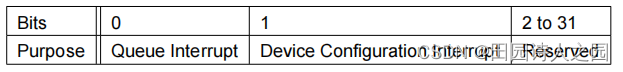
The ISR bits allow the driver to distinguish between device-specific configuration change interrupts and normal virtqueue interrupts:
To avoid an extra access, simply reading this register resets it to 0 and causes the device to de-assert the interrupt.
In this way, driver read of ISR status causes the device to de-assert an interrupt.
See sections 4.1.5.3 and 4.1.5.4 for how this is used.
1.4.5.1 Device Requirements: ISR status capability
The device MUST present at least one VIRTIO_PCI_CAP_ISR_CFG capability.
The device MUST set the Device Configuration Interrupt bit in ISR status before sending a device configu- ration change notification to the driver.
If MSI-X capability is disabled, the device MUST set the Queue Interrupt bit in ISR status before sending a virtqueue notification to the driver.
If MSI-X capability is disabled, the device MUST set the Interrupt Status bit in the PCI Status register in the PCI Configuration Header of the device to the logical OR of all bits in ISR status of the device. The device then asserts/deasserts INT#x interrupts unless masked according to standard PCI rules [PCI].
The device MUST reset ISR status to 0 on driver read.
1.4.5.2 Driver Requirements: ISR status capability
If MSI-X capability is enabled, the driver SHOULD NOT access ISR status upon detecting a Queue Interrupt.
1.4.6 Device-specific configuration
The device MUST present at least one VIRTIO_PCI_CAP_DEVICE_CFG capability for any device type which has a device-specific configuration.
1.4.6.1 Device Requirements: Device-specific configuration
The offset for the device-specific configuration MUST be 4-byte aligned.
1.4.7 Shared memory capability
Shared memory regions 2.10 are enumerated on the PCI transport as a sequence of VIRTIO_PCI_CAP_- SHARED_MEMORY_CFG capabilities, one per region.
The capability is defined by a struct virtio_pci_cap64 and utilises the cap.id to allow multiple shared memory regions per device. The identifier in cap.id does not denote a certain order of preference; it is only used to uniquely identify a region.
1.4.7.1 Device Requirements: Shared memory capability
The region defined by the combination of the cap.offset, offset_hi, and cap.length, length_hi fields MUST be contained within the BAR specified by cap.bar.
The cap.id MUST be unique for any one device instance.
1.4.8 Vendor data capability
The optional Vendor data capability allows the device to present vendor-specific data to the driver, without conflicts, for debugging and/or reporting purposes, and without conflicting with standard functionality.
This capability augments but does not replace the standard subsystem ID and subsystem vendor ID fields (offsets 0x2C and 0x2E in the PCI configuration space header) as specified by [PCI].
Vendor data capability is enumerated on the PCI transport as a VIRTIO_PCI_CAP_VENDOR_CFG capability.
The capability has the following structure:
struct virtio_pci_vndr_data {
	u8 cap_vndr;	/* Generic PCI field: PCI_CAP_ID_VNDR */
	u8 cap_next;	/* Generic PCI field: next ptr. */
	u8 cap_len;	/* Generic PCI field: capability length */
	u8 cfg_type;	/* Identifies the structure. */
	u16 vendor_id;	/* Identifies the vendor-specific format. */
	/* For Vendor Definition */
	/* Pads structure to a multiple of 4 bytes */
	/* Reads must not have side effects */
};
Where vendor_id identifies the PCI-SIG assigned Vendor ID as specified by [PCI].
Note that the capability size is required to be a multiple of 4.
To make it safe for a generic driver to access the capability, reads from this capability MUST NOT have any side effects.
1.4.8.1 Device Requirements: Vendor data capability
Devices CAN present vendor_id that does not match either the PCI Vendor ID or the PCI Subsystem Vendor ID.
Devices CAN present multiple Vendor data capabilities with either different or identical vendor_id values. The value vendor_id MUST NOT equal 0x1AF4.
The size of the Vendor data capability MUST be a multiple of 4 bytes.
Reads of the Vendor data capability by the driver MUST NOT have any side effects.
1.4.8.2 Driver Requirements: Vendor data capability
The driver SHOULD NOT use the Vendor data capability except for debugging and reporting purposes.
The driver MUST qualify the vendor_id before interpreting or writing into the Vendor data capability.
1.4.9 PCI configuration access capability
The VIRTIO_PCI_CAP_PCI_CFG capability creates an alternative (and likely suboptimal) access method to the common configuration, notification, ISR and device-specific configuration regions.
The capability is immediately followed by an additional field like so:
struct virtio_pci_cfg_cap {
	struct virtio_pci_cap cap;
	u8 pci_cfg_data[4]; /* Data for BAR access. */
};
The fields cap.bar, cap.length, cap.offset and pci_cfg_data are read-write (RW) for the driver.
To access a device region, the driver writes into the capability structure (ie. within the PCI configuration space) as follows:
• The driver sets the BAR to access by writing to cap.bar.
• The driver sets the size of the access by writing 1, 2 or 4 to cap.length.
• The driver sets the offset within the BAR by writing to cap.offset.
At that point, pci_cfg_data will provide a window of size cap.length into the given cap.bar at offset cap.offset.
1.4.9.1 Device Requirements: PCI configuration access capability
The device MUST present at least one VIRTIO_PCI_CAP_PCI_CFG capability.
Upon detecting driver write access to pci_cfg_data, the device MUST execute a write access at offset cap.offset at BAR selected by cap.bar using the first cap.length bytes from pci_cfg_data.
Upon detecting driver read access to pci_cfg_data, the device MUST execute a read access of length cap.length at offset cap.offset at BAR selected by cap.bar and store the first cap.length bytes in pci_cfg_data.
1.4.9.2 Driver Requirements: PCI configuration access capability
The driver MUST NOT write a cap.offset which is not a multiple of cap.length (ie. all accesses MUST be aligned).
The driver MUST NOT read or write pci_cfg_data unless cap.bar, cap.length and cap.offset address cap.length bytes within a BAR range specified by some other Virtio Structure PCI Capability of type other than VIR- TIO_PCI_CAP_PCI_CFG.
1.4.10 Legacy Interfaces: A Note on PCI Device Layout
Transitional devices MUST present part of configuration registers in a legacy configuration structure in BAR0 in the first I/O region of the PCI device, as documented below. When using the legacy interface, transitional drivers MUST use the legacy configuration structure in BAR0 in the first I/O region of the PCI device, as documented below.
When using the legacy interface the driver MAY access the device-specific configuration region using any width accesses, and a transitional device MUST present driver with the same results as when accessed using the “natural” access method (i.e. 32-bit accesses for 32-bit fields, etc).
Note that this is possible because while the virtio common configuration structure is PCI (i.e. little) endian, when using the legacy interface the device-specific configuration region is encoded in the native endian of the guest (where such distinction is applicable).
When used through the legacy interface, the virtio common configuration structure looks as follows:
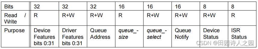
If MSI-X is enabled for the device, two additional fields immediately follow this header:
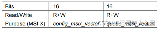
Note: When MSI-X capability is enabled, device-specific configuration starts at byte offset 24 in virtio common configuration structure structure. When MSI-X capability is not enabled, device-specific configuration starts at byte offset 20 in virtio header. ie. once you enable MSI-X on the device, the other fields move. If you turn it off again, they move back!
Any device-specific configuration space immediately follows these general headers:
When accessing the device-specific configuration space using the legacy interface, transitional drivers MUST access the device-specific configuration space at an offset immediately following the general headers.
When using the legacy interface, transitional devices MUST present the device-specific configuration space if any at an offset immediately following the general headers.
Note that only Feature Bits 0 to 31 are accessible through the Legacy Interface. When used through the Legacy Interface, Transitional Devices MUST assume that Feature Bits 32 to 63 are not acknowledged by Driver.
As legacy devices had no config_generation field, see 2.5.4 Legacy Interface: Device Configuration Space for workarounds.
1.4.11 Non-transitional Device With Legacy Driver: A Note on PCI Device Layout
All known legacy drivers check either the PCI Revision or the Device and Vendor IDs, and thus won’t attempt to drive a non-transitional device.
A buggy legacy driver might mistakenly attempt to drive a non-transitional device. If support for such drivers is required (as opposed to fixing the bug), the following would be the recommended way to detect and handle them.
Note: Such buggy drivers are not currently known to be used in production.
1.4.11.1 Device Requirements: Non-transitional Device With Legacy Driver
Non-transitional devices, on a platform where a legacy driver for a legacy device with the same ID (including PCI Revision, Device and Vendor IDs) is known to have previously existed, SHOULD take the following steps to cause the legacy driver to fail gracefully when it attempts to drive them:
- Present an I/O BAR in BAR0, and
- Respond to a single-byte zero write to offset 18 (corresponding to Device Status register in the legacy layout) of BAR0 by presenting zeroes on every BAR and ignoring writes.
1.5 PCI-specific Initialization And Device Operation
1.5.1 Device Initialization
This documents PCI-specific steps executed during Device Initialization.
1.5.1.1 Virtio Device Configuration Layout Detection
As a prerequisite to device initialization, the driver scans the PCI capability list, detecting virtio configuration layout using Virtio Structure PCI capabilities as detailed in 4.1.4
1.5.1.1.1 Legacy Interface: A Note on Device Layout Detection
Legacy drivers skipped the Device Layout Detection step, assuming legacy device configuration space in BAR0 in I/O space unconditionally.
Legacy devices did not have the Virtio PCI Capability in their capability list.
Therefore:
Transitional devices MUST expose the Legacy Interface in I/O space in BAR0.
Transitional drivers MUST look for the Virtio PCI Capabilities on the capability list. If these are not present, driver MUST assume a legacy device, and use it through the legacy interface.
Non-transitional drivers MUST look for the Virtio PCI Capabilities on the capability list. If these are not present, driver MUST assume a legacy device, and fail gracefully.
1.5.1.2 MSI-X Vector Configuration
When MSI-X capability is present and enabled in the device (through standard PCI configuration space) config_msix_vector and queue_msix_vector are used to map configuration change and queue interrupts to MSI-X vectors. In this case, the ISR Status is unused.
Writing a valid MSI-X Table entry number, 0 to 0x7FF, to config_msix_vector/queue_msix_vector maps interrupts triggered by the configuration change/selected queue events respectively to the corresponding MSI-X vector. To disable interrupts for an event type, the driver unmaps this event by writing a special NO_VECTOR value:
/* Vector value used to disable MSI for queue */
#define VIRTIO_MSI_NO_VECTOR 0xffff
Note that mapping an event to vector might require device to allocate internal device resources, and thus could fail.
1.5.1.2.1 Device Requirements: MSI-X Vector Configuration
A device that has an MSI-X capability SHOULD support at least 2 and at most 0x800 MSI-X vectors. De- vice MUST report the number of vectors supported in Table Size in the MSI-X Capability as specified in [PCI]. The device SHOULD restrict the reported MSI-X Table Size field to a value that might benefit system performance.
Note: For example, a device which does not expect to send interrupts at a high rate might only specify 2 MSI-X vectors.
Device MUST support mapping any event type to any valid vector 0 to MSI-X Table Size. Device MUST support unmapping any event type.
The device MUST return vector mapped to a given event, (NO_VECTOR if unmapped) on read of config_msix_vector/queue_msix_vector. The device MUST have all queue and configuration change events are unmapped upon reset.
Devices SHOULD NOT cause mapping an event to vector to fail unless it is impossible for the device to satisfy the mapping request. Devices MUST report mapping failures by returning the NO_VECTOR value when the relevant config_msix_vector/queue_msix_vector field is read.
1.5.1.2.2 Driver Requirements: MSI-X Vector Configuration
Driver MUST support device with any MSI-X Table Size 0 to 0x7FF. Driver MAY fall back on using INT#x interrupts for a device which only supports one MSI-X vector (MSI-X Table Size = 0).
Driver MAY intepret the Table Size as a hint from the device for the suggested number of MSI-X vectors to use.
Driver MUST NOT attempt to map an event to a vector outside the MSI-X Table supported by the device, as reported by Table Size in the MSI-X Capability.
After mapping an event to vector, the driver MUST verify success by reading the Vector field value: on success, the previously written value is returned, and on failure, NO_VECTOR is returned. If a mapping failure is detected, the driver MAY retry mapping with fewer vectors, disable MSI-X or report device failure.
1.5.1.3 Virtqueue Configuration
As a device can have zero or more virtqueues for bulk data transport1, the driver needs to configure them as part of the device-specific configuration.
The driver typically does this as follows, for each virtqueue a device has:
- Write the virtqueue index (first queue is 0) to queue_select.
- Read the virtqueue size from queue_size. This controls how big the virtqueue is (see 2.6 Virtqueues). If this field is 0, the virtqueue does not exist.
- Optionally, select a smaller virtqueue size and write it to queue_size.
- Allocate and zero Descriptor Table, Available and Used rings for the virtqueue in contiguous physical memory.
- Optionally, if MSI-X capability is present and enabled on the device, select a vector to use to request interrupts triggered by virtqueue events. Write the MSI-X Table entry number corresponding to this vector into queue_msix_vector. Read queue_msix_vector: on success, previously written value is returned; on failure, NO_VECTOR value is returned.
1.5.1.3.1 Legacy Interface: A Note on Virtqueue Configuration
When using the legacy interface, the queue layout follows 2.7.2 Legacy Interfaces: A Note on Virtqueue Layout with an alignment of 4096. Driver writes the physical address, divided by 4096 to the Queue Address field2 . There was no mechanism to negotiate the queue size.
1.5.2 Available Buffer Notifications
When VIRTIO_F_NOTIFICATION_DATA has not been negotiated, the driver sends an available buffer no- tification to the device by writing the 16-bit virtqueue index of this virtqueue to the Queue Notify address.
When VIRTIO_F_NOTIFICATION_DATA has been negotiated, the driver sends an available buffer notifica- tion to the device by writing the following 32-bit value to the Queue Notify address:
le32 {
	vqn : 16;
	next_off : 15;
	next_wrap : 1;
};
See 2.9 Driver Notifications for the definition of the components.
See 4.1.4.4 for how to calculate the Queue Notify address.
1.5.2.1 Driver Requirements: Available Buffer Notifications
If VIRTIO_F_NOTIF_CONFIG_DATA has been negotiated:
• If VIRTIO_F_NOTIFICATION_DATA has not been negotiated, the driver MUST use the queue_notify_data value instead of the virtqueue index.
• If VIRTIO_F_NOTIFICATION_DATA has been negotiated, the driver MUST set the vqn field to the queue_notify_data value.
1.5.3 Used Buffer Notifications
If a used buffer notification is necessary for a virtqueue, the device would typically act as follows:
• If MSI-X capability is disabled:
- Set the lower bit of the ISR Status field for the device.
- Send the appropriate PCI interrupt for the device.
• If MSI-X capability is enabled: - If queue_msix_vector is not NO_VECTOR, request the appropriate MSI-X interrupt message for the device, queue_msix_vector sets the MSI-X Table entry number.
1.5.3.1 Device Requirements: Used Buffer Notifications
If MSI-X capability is enabled and queue_msix_vector is NO_VECTOR for a virtqueue, the device MUST NOT deliver an interrupt for that virtqueue.
1.5.3.1 Device Requirements: Used Buffer Notifications
If MSI-X capability is enabled and queue_msix_vector is NO_VECTOR for a virtqueue, the device MUST NOT deliver an interrupt for that virtqueue.
1.5.4 Notification of Device Configuration Changes
Some virtio PCI devices can change the device configuration state, as reflected in the device-specific con- figuration region of the device. In this case:
• If MSI-X capability is disabled:
- Set the second lower bit of the ISR Status field for the device.
- Send the appropriate PCI interrupt for the device.
• If MSI-X capability is enabled: - If config_msix_vector is not NO_VECTOR, request the appropriate MSI-X interrupt message for the device, config_msix_vector sets the MSI-X Table entry number.
A single interrupt MAY indicate both that one or more virtqueue has been used and that the configuration space has changed.
1.5.4.1 Device Requirements: Notification of Device Configuration Changes
If MSI-X capability is enabled and config_msix_vector is NO_VECTOR, the device MUST NOT deliver an interrupt for device configuration space changes.
1.5.4.2 Driver Requirements: Notification of Device Configuration Changes
A driver MUST handle the case where the same interrupt is used to indicate both device configuration space change and one or more virtqueues being used.
1.5.5 Driver Handling Interrupts
The driver interrupt handler would typically:
• If MSI-X capability is disabled:
– Read the ISR Status field, which will reset it to zero.
– If the lower bit is set: look through all virtqueues for the device, to see if any progress has been made by the device which requires servicing.
– If the second lower bit is set: re-examine the configuration space to see what changed.
• If MSI-X capability is enabled:
– Look through all virtqueues mapped to that MSI-X vector for the device, to see if any progress has been made by the device which requires servicing.
– If the MSI-X vector is equal to config_msix_vector, re-examine the configuration space to see what changed.


 1825
1825

 被折叠的 条评论
为什么被折叠?
被折叠的 条评论
为什么被折叠?
 到【灌水乐园】发言


