


1 概述
本文主要介绍Linux下的IIO子系统使用,包括应用层访问,驱动层使用IIO子系统开发对应的驱动,同时对IIO子系统的配置含义以及IIO子系统源码框架进行分析。
为了使读者能快速理解,笔者文中提供了应用与驱动示例例程,在初步阅读掌握IIO的使用后,再深入IIO各个配置的含义以及其框架原理分析,深入掌握IIO子系统。
本文代码环境是在qemu模拟器执行的,关于该环境搭建可参数笔者之前写的博文:使用qemu搭建armv7嵌入式开发环境_qemu armv7-优快云博客
另外本文可能需要sysfs基础,可参考Linux configfs和sysfs的使用与理解-优快云博客
2 IIO子系统介绍
2.1 IIO子系统
IIO,全称 Industrial IO即工业 I/O,主要用于数字量和模拟量转换的IO接口设备接入Linux使用。这些设备种类较多,内部一般都会有一个ADC或者DAC,外部设备一般通过I2C/SPI等总线方式接入,驱动向上通过IIO提供访问接口,向下则接入这些设备。因此当使用的传感器本质是 ADC器件的时候,可以优先考虑使用 IIO 驱动框架。
IIO子系统主要涉及如下硬件设备的抽象管理(/usr/include/linux/iio/types.h中对IIO设备枚举中可看出):
模数转换器(ADC)
加速度计(Accelerometers)
陀螺仪(Gyros)
惯性测量单元 IMUs)
电容数字转换器 (CDC)
压力传感器
颜色、光线和接近传感器
温度传感器
磁力计(Magnetometers)
数模转换器(DAC)
直接数字合成器(DDS)
锁相环(PLL)
可变/可编程增益放大器(VGA、PGA)
2.2 IIO子系统框架
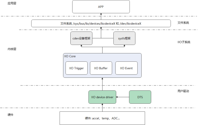
如下是IIO子系统在Linux中大致位置及框架组成。IIO子系统通过cdev设备向文件系统注册设备提供应用层访问IIO子系统的接口,也使用sysfs框架向应用层提供在Linux文件系统中修改访问的接口,前者在用户驱动使用trigger或buffer模式时使用,后者则在direct模型下使用。IIO子系统内主要用core、trigger、buffer和event几个模块组成,用户驱动根据自身需求,使用IIO子系统提供的注册接口,向子系统注册对应的channel信息以及访问的接口,这些信息与接口将有子系统在用户访问时分配访问和回调。
3 用户驱动的实现
在深入到IIO子系统之前,先通过一些例子看下如何使用IIO子系统开发用户驱动,并通过应用层访问到用用户驱动的。
3.1 模拟温度传感器例子(直接模式)
如下模拟了一个温度传感器驱动,使用iio子系统将温度值和温度比例值上传给用户。完成代码参考附录。
#define CHAN_SPEC(type_, index, mask) \
        { \
            .type = (type_), \
            .channel = (index), \
            .info_mask_separate = BIT(mask), \
            .address = 0, \
            .scan_index = 0, \
            .scan_type = { \
                .sign = 'u', \
                .realbits = 16, \
                .storagebits = 16, \
                .shift = 0, \
            }, \
            .indexed = 1, \
        }
static const struct iio_chan_spec temp_sensor_channels[] = {
    CHAN_SPEC(IIO_TEMP, 0, IIO_CHAN_INFO_RAW), //温度传感器中第一个通道
    CHAN_SPEC(IIO_TEMP, 1, IIO_CHAN_INFO_RAW),//温度传感器中第二个通道
    CHAN_SPEC(IIO_TEMP, 0, IIO_CHAN_INFO_SCALE)//温度传感的量程
};
static int temp_sensor_read_raw(struct iio_dev *indio_dev,
                                struct iio_chan_spec const *chan,
                                int *val, int *val2, long mask)
{
    switch (mask) {
    case IIO_CHAN_INFO_RAW://读取温度值
        *val = (chan->address == 0) ? 2500 : 3000; // 模拟温度值(0.25°C/0.30°C)
        return IIO_VAL_INT;
    case IIO_CHAN_INFO_SCALE://读取量程值
        *val = 83;
        return IIO_VAL_INT;
    default:
        return -EINVAL;
    }
}
static const struct iio_info temp_sensor_info = {
    .read_raw = temp_sensor_read_raw,
};
static int temp_sensor_probe(struct platform_device *pdev)
{
    struct iio_dev *indio_dev;
    int ret;
    //使用接口分配一个iio 设备
    indio_dev = devm_iio_device_alloc(&pdev->dev, sizeof(*indio_dev));
    if (!indio_dev)
        return -ENOMEM;
 	//填充用户配置,包括channel信息,模型,channel数量等。
    indio_dev->name = "virtual_temp_sensor";
    indio_dev->channels = temp_sensor_channels;
    indio_dev->num_channels = NUM_CHANNELS;
    indio_dev->info = &temp_sensor_info;
    indio_dev->modes = INDIO_DIRECT_MODE;//使用直接模型,提供sysfs
 //注册IIO
    ret = devm_iio_device_register(&pdev->dev, indio_dev);
    if (ret < 0)
        return ret;
    return 0;
}
如下是应用读取示例:
如下是根据上面驱动示例写的读取温度值应用,应用相应读取了in_temp0_raw和in_temp0_scale的值。
/*************************************************************************
 * File Name: iio_app.c
 * Author: xxx
 * Mail: xxx@xxx
 * Created Time: 2025年04月17日 星期四 14时59分24秒
 ************************************************************************/

#include <stdio.h>
#include <stdlib.h>
#include <fcntl.h>
#include <unistd.h>
#include <error.h>
 #include <string.h>
int main(int argc, char *argv[])
{
    char path[100] = {0};
    int fd = -1;
    char buffer[20] = {0};

    printf("iio sample app\n");
    // 读取通道0的原始值
    snprintf(path, sizeof(path), "/sys/bus/iio/devices/iio:device0/in_temp0_raw");
    fd = open(path, O_RDONLY);
    if(fd<0) {
        perror("/sys/bus/iio/devices/iio:device0/in_temp0_raw");
        return -1;
    }
    read(fd, buffer, sizeof(buffer));
    printf("Channel0 Raw: %s\n", buffer);
    close(fd);

    // 读取比例因子
    memset(buffer, 0, sizeof(buffer));
    memset(path, 0, sizeof(path));
    snprintf(path, sizeof(path), "/sys/bus/iio/devices/iio:device0/in_temp0_scale");
    fd = open(path, O_RDONLY);
    if(fd<0) {
        perror("/sys/bus/iio/devices/iio:device0/in_temp0_scale");
        return -1;
    }
    read(fd, buffer, sizeof(buffer));
    printf("Scale: %s\n", buffer);
    close(fd);

    return 0;
}
3.2 使用触发模式
如下是笔者模拟一个具有三路通道的温度传感器的iio驱动示例和应用层读取示例(完整代码见本文附录章节)。由于没有实际硬件支持,示例使用htimer计时中断来完成数据触发,推至IIO缓冲区中。
IIO设备,IIO触发器和hrtimer定时器的申请与注册流程:
static int temp_sensor_probe(struct platform_device *pdev)
{
    struct iio_dev *indio_dev;
    int ret;
    struct iio_tlab_data_ *tlab_p;
    struct device   *dev = &pdev->dev;
    //申请分配一个iio device
    indio_dev = devm_iio_device_alloc(&pdev->dev, sizeof(*tlab_p));
    if (!indio_dev)
        return -ENOMEM;
    tlab_p = iio_priv(indio_dev);//获取前面申请到的私有数据空间,这里用于struct iio_tlab_data_这个结构体
    mutex_init(&tlab_p->lock);
    tlab_p->dev = dev;
 	//通道信息的配置:三路通道,配置成触发模式,支持sysfs直接读
    indio_dev->name = DRV_NAME;
    indio_dev->channels = temp_sensor_channels;
    indio_dev->num_channels = NUM_CHANNELS;
    indio_dev->info = &temp_sensor_info;
    indio_dev->modes = INDIO_BUFFER_TRIGGERED;//触发模式
    /* 创建硬件触发器 */
    tlab_p->trigger = iio_trigger_alloc(&pdev->dev, "hrtimer-trig-%s", DRV_NAME);
    if (!tlab_p->trigger)
        return -ENOMEM;
    iio_trigger_set_drvdata(tlab_p->trigger, tlab_p);//配置控制数据维护
    tlab_p->trigger->ops = &temp_trigger_ops;//触发器回调配置
//触发器新增的属性配置,这里加了sampeling_frequency
tlab_p->trigger->dev.groups = temp_trigger_attr_groups;
ret = iio_trigger_register(tlab_p->trigger);
    if (ret) {
        iio_trigger_free(tlab_p->trigger);
        return ret;
}
//关联触发器到当前IIO设备中,这样子应用层不需要通过命令配置触发器
    indio_dev->trig = iio_trigger_get(tlab_p->trigger);
    ret = iio_triggered_buffer_setup(indio_dev,
        NULL,//上半部,这里记录时间戳
        &iio_trigger_handler, //下半部,处理缓冲区数据
        NULL);//使用默认的缓冲区
    ret = devm_iio_device_register(&pdev->dev, indio_dev);//注册IIO设备
    if (ret < 0)
        return ret;
//创建一个定时器
    hrtimer_init(&tlab_p->soft_timer, CLOCK_MONOTONIC, HRTIMER_MODE_REL);
    tlab_p->soft_timer.function  = soft_trigger_func;//配置定时中断处理函数
    hrtimer_start(&tlab_p->soft_timer, ktime_set(0, 500000000), HRTIMER_MODE_REL);//启动定时器
    dev_info(dev, "%s:%d successfully\n", __func__, __LINE__);

    return 0;
}
上述完成了IIO设备,IIO触发器和hrtimer定时器三者的创建与注册。
传感器通道描述结构体如下:
#define CHAN_SPEC(type_, index, mask, scind) \
        { \
            .type = (type_), \
            .channel = (index), \
            .info_mask_separate = BIT(mask), \
            .address = 0, \
            .scan_index = (scind), \
            .scan_type = { \
                .sign = 's', \
                .realbits = 32, \
                .storagebits = 32, \
                .endianness = IIO_CPU, \
            }, \
            .indexed = 1, \
        }

static const struct iio_chan_spec temp_sensor_channels[] = {
    CHAN_SPEC(IIO_TEMP, 0, IIO_CHAN_INFO_RAW, 0),//通道0
    CHAN_SPEC(IIO_TEMP, 1, IIO_CHAN_INFO_RAW, 1),//通道1
    CHAN_SPEC(IIO_TEMP, 2, IIO_CHAN_INFO_RAW, 2),//通道2
    IIO_CHAN_SOFT_TIMESTAMP(3), // 时间戳通道
};
上述完成了三路传感器通道定义,本例支持时间戳上传故多了一路时间戳通道。其中每路传感器通道值占32bit即4字节,一共12字节,加上时间戳8字节,一共20字节,注意这里scan_index不能重复,该域是IIO子系统扫描通道顺序值,源码有检查(后续源码分析)。
iio_dev的info回调集成员实现:
static const struct iio_info temp_sensor_info = {
    .read_raw = temp_sensor_read_raw,
    .attrs = &tmp006_attribute_group,
};
static IIO_CONST_ATTR(sampling_frequency_available, "4 2 1 0.5 0.25");

static struct attribute *tmp006_attributes[] = {
    &iio_const_attr_sampling_frequency_available.dev_attr.attr,
    NULL
};
static const struct attribute_group tmp006_attribute_group = {
    .attrs = tmp006_attributes,
};
这里只实现了read回调,上层可直接读取/sys/bus/iio/devices/iio:device0/in_temp0_raw来获取当前通道0的值,其他通道同理。同时这里还实现了一个属性sample_frequency采样率的配置枚举,假设支持的采样率有"4 2 1 0.5 0.25"。
触发器回调实现为NULL:
static const struct iio_trigger_ops temp_trigger_ops = {
    .set_trigger_state = NULL, /* 由sysfs触发器管理状态 */
};
触发器属性增加了sample_frequency采样率的配置:
/* 触发器属性操作:频率配置 */
static ssize_t sampling_frequency_store(struct device *dev,
    struct device_attribute *attr,
    const char *buf, size_t len)
{
    struct iio_trigger *trig = to_iio_trigger(dev);
    struct iio_tlab_data_ *tlab_p = iio_trigger_get_drvdata(trig);
    unsigned int freq;

    if (kstrtou32(buf, 10, &freq)) {
        return -EINVAL;
    }
    tlab_p->sampling_freq = freq;
    return len;
}
static ssize_t sampling_frequency_show(struct device *dev,
     struct device_attribute *attr,
     char *buf)
{
    struct iio_trigger *trig = to_iio_trigger(dev);
    struct iio_tlab_data_ *tlab_p = iio_trigger_get_drvdata(trig);
    return sprintf(buf, "%u\n", tlab_p->sampling_freq);
}
static IIO_DEV_ATTR_SAMP_FREQ(S_IWUSR | S_IRUGO,
    sampling_frequency_show,
    sampling_frequency_store);
static struct attribute *temp_trigger_attrs[] = {
    &iio_dev_attr_sampling_frequency.dev_attr.attr,
    NULL,
};
static const struct attribute_group temp_trigger_attr_group = {
    .attrs = temp_trigger_attrs,
};
static const struct attribute_group *temp_trigger_attr_groups[] = {
    &temp_trigger_attr_group,
    NULL,
};
可根据需求增加其他属性的配置,如量程、带宽、校准值之类的属性值配置。
触发器缓冲区配置中,触发回调实现如下(可实现上半部下半部):
/* 触发器下半部(内核线程上下文) */
irqreturn_t iio_trigger_handler(int irq, void *p)
{
    const struct iio_poll_func *pf = p;
    struct iio_dev *indio_dev = pf->indio_dev;
    struct iio_tlab_data_ *tlab_p = iio_priv(indio_dev);
    struct temtemp_fb_data_ *val = (struct temtemp_fb_data_ *)tlab_p->buffer;

    if(!tlab_p) {
        printk("null error\n");
        return IRQ_HANDLED;
    }

    mutex_lock(&tlab_p->lock);
    /* 模拟从硬件读取数据 */
    val->temp_val[0] = read_adc_channel(0);
    val->temp_val[1] = read_adc_channel(1);
    val->temp_val[2] = read_adc_channel(2);
    val->timestamp = iio_get_time_ns(indio_dev);
    /* 推送数据到缓冲区 */
    iio_push_to_buffers_with_timestamp(indio_dev, tlab_p->buffer, val->timestamp);
    // iio_push_to_buffers(indio_dev, tlab_p->buffer);
    /* 完成触发处理 */
    iio_trigger_notify_done(indio_dev->trig);
    mutex_unlock(&tlab_p->lock);
    return IRQ_HANDLED;
}
这里实现了下半部,主要读取每个通道的温度值后,通过 iio_push_to_buffers_with_timestamp接口推送到IIO数据缓冲区,再完成触发处理。应用层将在每一帧数据中拿到 channel0+channel1+channel2+timesmap四个数据。
Hrtimer定时器的回调主要是重启定时,不断调用中断处理函数,通道触发器处理当前中断。
static enum hrtimer_restart soft_trigger_func(struct hrtimer *timer)
{
    struct iio_tlab_data_ *tlab_p = container_of(timer, struct iio_tlab_data_, soft_timer);
    hrtimer_forward_now(timer, ktime_set(0, 100000000)); // 2Hz触发
    iio_trigger_poll(tlab_p->trigger);
    return HRTIMER_RESTART;
}
上述完成的驱动后加入内核编译启动,iio:device信息如下:
/sys/bus/iio/devices/iio:device0
[root@qemu_armv7 iio:device0]# tree
.
├── buffer
│   ├── data_available
│   ├── enable
│   ├── length
│   └── watermark
├── buffer0
│   ├── data_available
│   ├── enable
│   ├── in_temp0_en
│   ├── in_temp0_index
│   ├── in_temp0_type
│   ├── in_temp1_en
│   ├── in_temp1_index
│   ├── in_temp1_type
│   ├── in_temp2_en
│   ├── in_temp2_index
│   ├── in_temp2_type
│   ├── in_timestamp_en
│   ├── in_timestamp_index
│   ├── in_timestamp_type
│   ├── length
│   └── watermark
├── current_timestamp_clock
├── dev
├── in_temp0_raw
├── in_temp1_raw
├── in_temp2_raw
├── name
├── of_node -> ../../../../firmware/devicetree/base/temp-sensor@0
├── power
│   ├── autosuspend_delay_ms
│   ├── control
│   ├── runtime_active_time
│   ├── runtime_status
│   └── runtime_suspended_time
├── sampling_frequency_available
├── scan_elements
│   ├── in_temp0_en
│   ├── in_temp0_index
│   ├── in_temp0_type
│   ├── in_temp1_en
│   ├── in_temp1_index
│   ├── in_temp1_type
│   ├── in_temp2_en
│   ├── in_temp2_index
│   ├── in_temp2_type
│   ├── in_timestamp_en
│   ├── in_timestamp_index
│   └── in_timestamp_type
├── subsystem -> ../../../../bus/iio
├── trigger
│   └── current_trigger
└── uevent
5 directories, 48 files
在dev下生成了iio:device0设备:
![]()
接下来应用层的实现,对三路通道温度值和时间戳实时读取:
#include <stdio.h>
#include <fcntl.h>
#include <unistd.h>
#include <sys/ioctl.h>
#include <string.h>

#define CHANNEL_NUM 3
#define ALIGN_8(x) (((x) + 7) & ~7)
#define CHANNEL_DATA_BUFFER_LEN ALIGN_8(CHANNEL_NUM*4)
#define IIO_DEVICE_PATH "/sys/bus/iio/devices/iio:device0"
#define TRIGGER_PATH "/sys/bus/iio/devices/trigger0"
typedef struct temtemp_fb_data_ {
    int temp_val;
    unsigned int timestamp;
}temp_fb_data;
int main() {
    int fd, ret;
    char buf[CHANNEL_DATA_BUFFER_LEN + 8] = {0};
    temp_fb_data fdat;
    /* 设置hrtimer触发 */
    int trig_fd = open(IIO_DEVICE_PATH "/scan_elements/in_temp0_en", O_WRONLY);
    write(trig_fd, "1", 1);
    close(trig_fd);
    trig_fd = open(IIO_DEVICE_PATH "/buffer/length", O_WRONLY);
    write(trig_fd, "256", 3);
    close(trig_fd);
    trig_fd = open(IIO_DEVICE_PATH "/scan_elements/in_timestamp_en", O_WRONLY);
    write(trig_fd, "1", 1);
    close(trig_fd);
    trig_fd = open(IIO_DEVICE_PATH "/buffer/enable", O_WRONLY);
    write(trig_fd, "1", 1);
    close(trig_fd);

    /* 配置采样频率(单位:Hz) */
    int freq_fd = open(TRIGGER_PATH "/sampling_frequency", O_WRONLY);
    if(freq_fd < 0) {
        perror("sampling_frequency");
    } else {
        write(freq_fd, "10", 2);
    }
    close(freq_fd);
    /* 打开字符设备读取数据 */
    fd = open("/dev/iio:device0", O_RDONLY);
    if (fd < 0) {
        perror("Failed to open device");
        return 1;
    }
    while (1) {
        ssize_t len = read(fd, buf, sizeof(buf));
        if (len >= 0) {
            int *raw_temp = (int *)buf;
            for(int i=0;i<CHANNEL_NUM;i++) {
                printf("channel%d:%d°C ", i, raw_temp[i]);
            }
            unsigned long long *ts = (unsigned long long *)(buf+sizeof(buf)-8);
            printf("timesmap:%lluns\n", ts[0]);
        }
        usleep(500000); // 100ms间隔
    }
    close(fd);
    return 0;
}
应用示例中有几个比较关键的流程:
(1)使能数据的触发流程:
1)使能通道数据
echo 1 > /sys/bus/iio/devices/iio:device0/scan_elements/in_temp0_en
echo 1 > /sys/bus/iio/devices/iio:device0/scan_elements/in_temp1_en
echo 1 > /sys/bus/iio/devices/iio:device0/scan_elements/in_temp2_en
echo 1 > /sys/bus/iio/devices/iio:device0/scan_elements/in_timestamp_en
2)设置缓冲区大小256
echo 256 > /sys/bus/iio/devices/iio:device0/buffer/length3)使能缓冲区触发
echo 1 > /sys/bus/iio/devices/iio:device0/buffer/enable(2)读取数据值
打开设备/dev/iio:device0,读取buf长度的数据,按通道值一个一个拆分,需要注意的是,这里由于驱动上传了timesmap 8字节,前面通道数据也需要8字节对齐,即这里字节数一共24字节。
#define CHANNEL_NUM 3
#define ALIGN_8(x) (((x) + 7) & ~7)
#define CHANNEL_DATA_BUFFER_LEN ALIGN_8(CHANNEL_NUM*4)

  char buf[CHANNEL_DATA_BUFFER_LEN + 8] = {0};
当上传时间戳需要8字节对齐,是由IIO子系统绝定,在IIO子系统源码中(include/linux/iio/buffer.h),时间戳被加在通道数据8对齐后的8个字节当中。
static inline int iio_push_to_buffers_with_timestamp(struct iio_dev *indio_dev,
    void *data, int64_t timestamp)
{
    if (indio_dev->scan_timestamp) {
        size_t ts_offset = indio_dev->scan_bytes / sizeof(int64_t) - 1;
        ((int64_t *)data)[ts_offset] = timestamp;
    }
    return iio_push_to_buffers(indio_dev, data);
}
(3)触发器配置
这里没有配置触发器,是因为驱动已经创建了触发器通道绑定触发器到该IIO device上。也可通过应用层来创建触发器:
echo 0 > /sys/devices/iio_sysfs_trigger/add_trigger
echo "sysfstrig0" > /sys/bus/iio/devices/trigger0/name
echo "sysfstrig0" > /sys/bus/iio/devices/iio:device0/trigger/current_trigger
其中trigger0/name和iio:device0/trigger/current_trigger的名称需要一致才能将device绑定到创建的触发器上,这里名称为sysfstrig0。
(4)关闭触发
不使用的情况下,关闭通道触发
echo 0 > /sys/bus/iio/devices/iio:device0/buffer/enable(5)使用命令行读取触发模式下的值
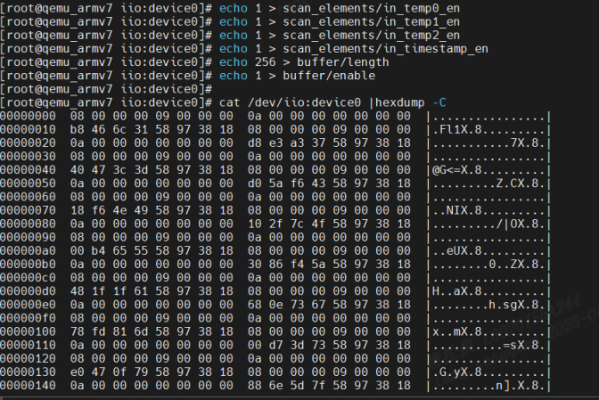
上述流程其实也能直接在命令验证执行,有时为了验证驱动正确性比较方便;通过执行上述命令打开通道触发数据后,通过如下命令可直接查看数据的情况:
cat /dev/iio:device0 | hexdump -C如下是实际效果:
3.3 IIO一些关键字段值含义解释
3.3.1 通道字段
如下是通道描述结构体,通道个字段含义如下:
struct iio_chan_spec {
enum iio_chan_type type;//表示channel类型,电压、电流、加速度、电磁等等。
//通道数值,在indexed为1时有效,例如in_temp0_raw\in_temp1_raw,不能重复
int channel;
//通道描述值,在modified为1时有效,例如in_scalex_raw、in_scaley_raw,不能重复
int channel2;
unsigned long address;//该通道对应的芯片数据寄存器地址
int scan_index;//当使用触发缓冲区的时候,scan_index 是扫描索引,每个通道的scan_index不能重复
struct {
char sign;//当前通道缓冲区数值类型,s为有符号,u为无符号
u8 realbits;//当前有效位,数据真实的有效位数,比如很多传感器说的 10 位 ADC,其真实有效数 据就是 10 位。
u8 storagebits;//当前通道传递的位数.存储位数,有效位数+填充位。比如有些传感器 ADC 是 12 位的, 那么我们存储的话肯定要用到 2 个字节,也就是 16 位,这 16 位就是存储位数。
u8 shift;//右移位数,也就是存储位数和有效位数不一致的时候,需要右移的位数,这 个参数不总是需要,一切以实际芯片的数据手册位数
u8 repeat;//实际或存储位的重复数量。
enum iio_endian endianness;//数据的大小端模式,可设置为 IIO_CPU、IIO_BE(大端)或 IIO_LE(小 端)。
} scan_type;//扫描数据的存储格式
//声明通道支持的独立操作(如读取原始值、偏移量等),例如BIT(IIO_CHAN_INFO_RAW) | BIT(IIO_CHAN_INFO_SCALE)
long info_mask_separate;
//用于声明通道支持的可枚举属性的掩码,指示该通道的某些属性具有多个可选值(如采样频率、量程等),用户可通过 sysfs 查看所有可选参数列表
long info_mask_separate_available;
//标记导出的信息由相同类型的通道共享。X、Y、Z轴他们的 type 都 是IIO_ACCEL,也就是类型相同。而这三个轴的分辨率(量程)是一样的,那么这3个通道
long info_mask_shared_by_type;
long info_mask_shared_by_type_available;
//标记某些导出的信息由相同方向的通道共享
long info_mask_shared_by_dir;
long info_mask_shared_by_dir_available;
//表设计某些信息所有的通道共享,无论这些通道的类 型、方向如何,全部共享。
long info_mask_shared_by_all;
long info_mask_shared_by_all_available;
//它定义了事件的类型、触发阈值、数据格式等参数,供内核与用户态交互.
const struct iio_event_spec *event_spec;
unsigned int num_event_specs;
const struct iio_chan_spec_ext_info *ext_info;
//用于为通道提供扩展标识符的成员变量,主要解决同类传感器的多通道区分问题,增强用户空间对数据来源的识别能力,例如.extend_name = "external",用户层为in_temp_external_raw 文件
const char *extend_name;
const char *datasheet_name;
unsigned modified:1;//modified 为 1 的时候,channel2 为通道修饰符
unsigned indexed:1;// indexed 为 1时候,channel 为通道索引
unsigned output:1;//表示为输出通道
unsigned differential:1;//表示为差分通道
};通道类型枚举值:
enum iio_chan_type {
    IIO_VOLTAGE, /* 电压类型 */
    IIO_CURRENT, /* 电流类型 */
    IIO_POWER, /* 功率类型 */
    IIO_ACCEL, /* 加速度类型 */
    IIO_ANGL_VEL, /* 角度类型(陀螺仪) */
    IIO_MAGN, /* 电磁类型(磁力计) */
    IIO_LIGHT, /* 灯光类型 */
    IIO_INTENSITY, /* 强度类型(光强传感器) */
    IIO_PROXIMITY, /* 接近类型(接近传感器) */
    IIO_TEMP, /* 温度类型 */
    IIO_INCLI, /* 倾角类型(倾角测量传感器) */
    IIO_ROT, /* 旋转角度类型 */
    IIO_ANGL, /* 转动角度类型(电机旋转角度测量传感器) */
    IIO_TIMESTAMP, /* 时间戳类型 */
    IIO_CAPACITANCE, /* 电容类型 */
    IIO_ALTVOLTAGE, /* 频率类型 */
    IIO_CCT, /* 笔者暂时未知的类型 */
    IIO_PRESSURE, /* 压力类型 */
    IIO_HUMIDITYRELATIVE, /* 湿度类型 */
    IIO_ACTIVITY, /* 活动类型(计步传感器) */
    IIO_STEPS, /* 步数类型 */
    IIO_ENERGY, /* 能量类型(卡路里) */
    IIO_DISTANCE, /* 距离类型 */
    IIO_VELOCITY, /* 速度类型 */
};
3.3.2 模式
IIO子系统常见的模式如下:
/* Device operating modes */
/*
/直接模式,子系统提供 sysfs 接口,用户可立即从硬件读取当前值
作用:支持用户空间通过 sysfs 单次读取指定通道的即时数据。
示例:
温度传感器驱动中,用户通过 /sys/bus/iio/devices/iio:deviceX/in_temp_input 文件直接读取当前温度值
struct iio_dev *indio_dev = iio_device_alloc();
indio_dev->modes = INDIO_DIRECT_MODE;
*/
#define INDIO_DIRECT_MODE 0x01
//触发模式,通过缓冲区方式触发推送给用户
/*
作用:启用基于硬件或软件触发器(如定时器、GPIO中断)的连续数据缓冲采集。
示例:加速度计驱动绑定 iio-trig-hrtimer 触发器,按固定频率采集三轴数据到缓冲区:
indio_dev->modes = INDIO_BUFFER_TRIGGERED;
iio_triggered_buffer_setup(indio_dev, NULL, &trigger_handler, NULL);
*/
#define INDIO_BUFFER_TRIGGERED 0x02
//软件缓冲
/*
作用:由内核驱动自主管理缓冲填充逻辑,无需外部触发器。
示例:光传感器驱动周期性读取环境光强度并填充缓冲区:
indio_dev->modes = INDIO_BUFFER_SOFTWARE;
iio_push_to_buffers(indio_dev, &data); // 手动推送数据
*/
#define INDIO_BUFFER_SOFTWARE 0x04
//支持硬件缓冲
/*
作用:依赖硬件模块(如 DMA)自动管理数据搬运,适用于高速采集场景。
示例:高速 ADC 驱动使用 DMA 通道直接将采样数据写入内核缓冲区:
indio_dev->modes = INDIO_BUFFER_HARDWARE;
iio_dmaengine_buffer_setup(indio_dev, "adc_dma"); // 配置 DMA 引擎
*/
#define INDIO_BUFFER_HARDWARE 0x08
//事件类型的触发,当传感器值到达某个值时,IIO子系统自动触发上传
/*
作用:支持阈值超限或状态变化事件的检测与上报。
示例:陀螺仪驱动配置角速度超阈值触发中断:
static const struct iio_event_spec gyro_event = {
.type = IIO_EV_TYPE_THRESH,
.dir = IIO_EV_DIR_RISING,
};
indio_dev->modes = INDIO_EVENT_TRIGGERED;
*/
#define INDIO_EVENT_TRIGGERED 0x10
//硬件触发
/*
作用:依赖外部硬件信号(如 GPIO 上升沿)启动数据采集。
示例:压力传感器驱动绑定外部 GPIO 触发信号:
struct iio_trigger *trig = iio_trigger_alloc("gpio-trigger");
gpio_request(trig_pin, "pressure_trig");
indio_dev->modes = INDIO_HARDWARE_TRIGGERED;
iio_trigger_register(trig);
*/
#define INDIO_HARDWARE_TRIGGERED 0x20本文举例了INDIO_DIRECT_MODE和INDIO_BUFFER_TRIGGERED。
3.3.3 iio_info-属性和函数实现
如下是strcut iio_dev下的info成员结构体内容
struct iio_info {
    const struct attribute_group    *event_attrs;
    const struct attribute_group    *attrs;
    int (*read_raw)(struct iio_dev *indio_dev,
            struct iio_chan_spec const *chan,
            int *val,
            int *val2,
            long mask);
    int (*read_raw_multi)(struct iio_dev *indio_dev,
            struct iio_chan_spec const *chan,
            int max_len,
            int *vals,
            int *val_len,
            long mask);
    int (*read_avail)(struct iio_dev *indio_dev,
              struct iio_chan_spec const *chan,
              const int **vals,
              int *type,
              int *length,
              long mask);
    int (*write_raw)(struct iio_dev *indio_dev,
             struct iio_chan_spec const *chan,
             int val,
             int val2,
             long mask);
    int (*read_label)(struct iio_dev *indio_dev,
             struct iio_chan_spec const *chan,
             char *label);
    int (*write_raw_get_fmt)(struct iio_dev *indio_dev,
             struct iio_chan_spec const *chan,
             long mask);
    int (*read_event_config)(struct iio_dev *indio_dev,
                 const struct iio_chan_spec *chan,
                 enum iio_event_type type,
                 enum iio_event_direction dir);
    int (*write_event_config)(struct iio_dev *indio_dev,
                  const struct iio_chan_spec *chan,
                  enum iio_event_type type,
                  enum iio_event_direction dir,
                  int state);
    int (*read_event_value)(struct iio_dev *indio_dev,
                const struct iio_chan_spec *chan,
                enum iio_event_type type,
                enum iio_event_direction dir,
                enum iio_event_info info, int *val, int *val2);
    int (*write_event_value)(struct iio_dev *indio_dev,
                 const struct iio_chan_spec *chan,
                 enum iio_event_type type,
                 enum iio_event_direction dir,
                 enum iio_event_info info, int val, int val2);
    int (*validate_trigger)(struct iio_dev *indio_dev,
                struct iio_trigger *trig);
    int (*update_scan_mode)(struct iio_dev *indio_dev,
                const unsigned long *scan_mask);
    int (*debugfs_reg_access)(struct iio_dev *indio_dev,
                  unsigned reg, unsigned writeval,
                  unsigned *readval);
    int (*of_xlate)(struct iio_dev *indio_dev,
            const struct of_phandle_args *iiospec);
    int (*hwfifo_set_watermark)(struct iio_dev *indio_dev, unsigned val);
    int (*hwfifo_flush_to_buffer)(struct iio_dev *indio_dev,
                      unsigned count);
};
两个struct attribute_group成员,用于配置iio_dev 的特有属性值,在前面举例的应用中有使用到,可以配置传感器一些配置参数。
其他的都是一些回调,这里重点需要说明下回调中val和val2以及返回值:对于 read_raw来说 val 和 val2 这两个就是应用程序从内核空间读取到数据,一般就是传感器指定通道值,或者传感器的量程、分辨率等。对于 write_raw 来说就是应用程序向设备写入的数据。val 和 val2 共同组成具体值,val 是整数部分,val2 是小数部分。Linux内核无法支持浮点运算,因此val2是放大后的值。扩大的倍数我们不能随便设置,而是要使用 Linux 定义的倍数,Linux 内核里面定义的数据扩大倍数:
| 组合宏 | 描述 |
| IJO_VAL_INT | 整数值,没有小数。比如5000,那么就是val = 5000,不需要设置val2 |
| IJO_VAL_INT_PLUS_MICRO | 小数部分扩大1000000倍,比如1.00236,此时val = 1,val2 = 2360 |
| IJO_VAL_INT_PLUS_NANO | 小数部分扩大1000000000倍,同样是1.00236,此时val = 1,val2 = 2360000 |
| IJO_VAL_INT_PLUS_MICRO_DB | dB数据,和IJO_VAL_INT_PLUS_MICRO数据形式一样,只是在后面添加db |
| IJO_VAL_INT_MULTIPLE | 多个整数值,比如一次要传回6个整数值,那么val和val2就不够用了。此宏主要用于iio_info的read_raw_multi函数 |
| IJO_VAL_FRACTIONAL | 分数值,也就是val/val2。比如val = 1,val2 = 4,那么实际值就是1/4 |
| IJO_VAL_FRACTIONAL_LOG2 | val>>val2,也就是val右移val2位。比如val = 25600,val2 = 4,那么真正的值就是25600右移4位,25600>>4=1600 |
4 IIO子系统源码分析
4.1 IIO子系统内核配置
在kernel中使用IIO子系统,需要先配置打开如下选项:
CONFIG_IIO=y
CONFIG_IIO_BUFFER=y
CONFIG_IIO_TRIGGERED_BUFFER=y
CONFIG_IIO_SYSFS_TRIGGER=y
CONFIG_IIO_SW_TRIGGER=y
CONFIG_IIO_TRIGGER=y
CONFIG_IIO_INTERRUPT_TRIGGER=y
CONFIG_IIO_HRTIMER_TRIGGER=y
4.2 分析注册流程
4.2.1 devm_iio_device_alloc
该接口位于drivers/iio/industrialio-core.c,用户分配初始化IIO控制相关的结构体内存。
devm_iio_device_alloc
==>iio_device_alloc
struct iio_dev *iio_device_alloc(struct device *parent, int sizeof_priv)
{
    struct iio_dev_opaque *iio_dev_opaque;
    struct iio_dev *indio_dev;
    size_t alloc_size;
//这里计算了结构体struct iio_dev_opaque和sizeof_priv的大小,其中sizeof_priv是用户内存大小,一般用户驱动维护内存
    alloc_size = sizeof(struct iio_dev_opaque);
    if (sizeof_priv) {
        alloc_size = ALIGN(alloc_size, IIO_ALIGN);
        alloc_size += sizeof_priv;
    }
    iio_dev_opaque = kzalloc(alloc_size, GFP_KERNEL);
    if (!iio_dev_opaque)
        return NULL;
indio_dev = &iio_dev_opaque->indio_dev;
//偏移出用户内存地址
    indio_dev->priv = (char *)iio_dev_opaque +
        ALIGN(sizeof(struct iio_dev_opaque), IIO_ALIGN);
   ...
//下面是iio:deviceX中X的逻辑,使用idr生成对应维护的id,该id即是X的值
    iio_dev_opaque->id = ida_simple_get(&iio_ida, 0, 0, GFP_KERNEL);
    ...
    if (dev_set_name(&indio_dev->dev, "iio:device%d", iio_dev_opaque->id)) {
        ida_simple_remove(&iio_ida, iio_dev_opaque->id);
        kfree(iio_dev_opaque);
        return NULL;
    }
   ...
    return indio_dev;
}
devm_iio_device_alloc比较简单,主要是内存的申请和iio:deviceX设备名称的生成。
4.2.2 devm_iio_device_register
该宏定义在include/linux/iio/iio.h中:
#define devm_iio_device_register(dev, indio_dev) \
    __devm_iio_device_register((dev), (indio_dev), THIS_MODULE)
__devm_iio_device_register 定义在drivers/iio/industrialio-core.c:
__devm_iio_device_register
==>__iio_device_register
int __iio_device_register(struct iio_dev *indio_dev, struct module *this_mod)
{
    struct iio_dev_opaque *iio_dev_opaque = to_iio_dev_opaque(indio_dev);
   ...
//检查通道参数里scan_index值,不能重复
    ret = iio_check_unique_scan_index(indio_dev);
  ...
//检查通道的拓展名称,驱动用户不能同事实现read_label回调和extended_name赋值。
    ret = iio_check_extended_name(indio_dev);
 ...
//buffer模式相关,后面分析
    ret = iio_buffers_alloc_sysfs_and_mask(indio_dev);
   ...
//为每个通道做初始化,包括sysfs需要的attr,read/write回调赋值,后面分析
    ret = iio_device_register_sysfs(indio_dev);
   ...
//event模式下初始化通道属性等
    ret = iio_device_register_eventset(indio_dev);
   ...
//buffer模型,赋值ops
    if ((indio_dev->modes & INDIO_ALL_BUFFER_MODES) &&
        indio_dev->setup_ops == NULL)
        indio_dev->setup_ops = &noop_ring_setup_ops;
//buffer模式的操作集赋值
    if (iio_dev_opaque->attached_buffers_cnt)
        cdev_init(&iio_dev_opaque->chrdev, &iio_buffer_fileops);
    else if (iio_dev_opaque->event_interface)
        cdev_init(&iio_dev_opaque->chrdev, &iio_event_fileops);//event操作集赋值
if (iio_dev_opaque->attached_buffers_cnt || iio_dev_opaque->event_interface) {
//初始化cdev成员
        indio_dev->dev.devt = MKDEV(MAJOR(iio_devt), iio_dev_opaque->id);
        iio_dev_opaque->chrdev.owner = this_mod;
    }
    /* assign device groups now; they should be all registered now */
    indio_dev->dev.groups = iio_dev_opaque->groups;//sysfs group赋值到device中
    //该接口注册cdev设备同时调用sysfs接口生成对应的设备文件。
ret = cdev_device_add(&iio_dev_opaque->chrdev, &indio_dev->dev);
 ....
}
__devm_iio_device_register最主要工作是为生成设备而做各个初始化,包括为每个通道赋值sysfs attr,生成cdev前的device初始化等。其中为每个通道生成sysfs配置接口为iio_device_register_sysfs:
static int iio_device_register_sysfs(struct iio_dev *indio_dev)
{
    struct iio_dev_opaque *iio_dev_opaque = to_iio_dev_opaque(indio_dev);
    int i, ret = 0, attrcount, attrn, attrcount_orig = 0;
    struct iio_dev_attr *p;
    struct attribute **attr, *clk = NULL;
    ...
    /*
     这里为每个通道添加sysfs属性
     */
    if (indio_dev->channels)
        for (i = 0; i < indio_dev->num_channels; i++) {
            const struct iio_chan_spec *chan =
                &indio_dev->channels[i];
            if (chan->type == IIO_TIMESTAMP)
                clk = &dev_attr_current_timestamp_clock.attr;
            ret = iio_device_add_channel_sysfs(indio_dev, chan);//生成添加sysfs
            if (ret < 0)
                goto error_clear_attrs;
            attrcount += ret;
        }
   ...
//取出前面每个通道属性数据到attrs,同时放到iio_dev_opaque->groups中,前面 cdev_device_add用的即是这个sysfs group
    list_for_each_entry(p, &iio_dev_opaque->channel_attr_list, l)
        iio_dev_opaque->chan_attr_group.attrs[attrn++] = &p->dev_attr.attr;
    if (indio_dev->name)
        iio_dev_opaque->chan_attr_group.attrs[attrn++] = &dev_attr_name.attr;
    if (indio_dev->label)
        iio_dev_opaque->chan_attr_group.attrs[attrn++] = &dev_attr_label.attr;
    if (clk)
        iio_dev_opaque->chan_attr_group.attrs[attrn++] = clk;
    ret = iio_device_register_sysfs_group(indio_dev,
                          &iio_dev_opaque->chan_attr_group);
...
    return ret;
}
接下里看下如何为每个通道生成并初始化sysfs的attr的:
static int iio_device_add_channel_sysfs(struct iio_dev *indio_dev,
                    struct iio_chan_spec const *chan)
{
    struct iio_dev_opaque *iio_dev_opaque = to_iio_dev_opaque(indio_dev);
...
//当前通道info_mask_separate属性处理,info_mask_separate例如raw,scale等
    ret = iio_device_add_info_mask_type(indio_dev, chan,
                        IIO_SEPARATE,
                        &chan->info_mask_separate);
...
//添加该属性值available状态
    ret = iio_device_add_info_mask_type_avail(indio_dev, chan,
                          IIO_SEPARATE,
                          &chan->
                          info_mask_separate_available);
 ...
//接下来调用相同接口,处理info_mask_shared_by_type、info_mask_shared_by_type_available、info_mask_shared_by_dir、info_mask_shared_by_dir_available
  ...
//同样方式处理label,添加对应的sysfs attr
    ret = iio_device_add_channel_label(indio_dev, chan);
 ...
}
__iio_add_chan_devattr调用如实现:
static int iio_device_add_info_mask_type(struct iio_dev *indio_dev,
                     struct iio_chan_spec const *chan,
                     enum iio_shared_by shared_by,
                     const long *infomask)
{
    struct iio_dev_opaque *iio_dev_opaque = to_iio_dev_opaque(indio_dev);
int i, ret, attrcount = 0;
//轮询每个bit位,例如在处理info_mask_separate时,前面示例配置了raw、scale
    for_each_set_bit(i, infomask, sizeof(*infomask)*8) {
        if (i >= ARRAY_SIZE(iio_chan_info_postfix))
            return -EINVAL;
        ret = __iio_add_chan_devattr(iio_chan_info_postfix[i], chan,
                         &iio_read_channel_info,//这里传入了应用用户将回调的read接口
                         &iio_write_channel_info,//write接口
                         i,shared_by,&indio_dev->dev,NULL,&iio_dev_opaque->channel_attr_list);
        ...
    }
    ..
}
如上分析了注册IIO接口devm_iio_device_register的过程,可看出最主要的还是在为每个通道生成设备而初始化做准备,以使应用用户操作设备时,能正确回调用驱动用户的回调接口中。
4.2.3 iio_triggered_buffer_setup
该接口是定义于include/linux/iio/triggered_buffer.h的宏定义:
#define iio_triggered_buffer_setup(indio_dev, h, thread, setup_ops)     \
    iio_triggered_buffer_setup_ext((indio_dev), (h), (thread), (setup_ops), NULL)
iio_triggered_buffer_setup_ext实现在drivers/iio/buffer/industrialio-triggered-buffer.c
int iio_triggered_buffer_setup_ext(struct iio_dev *indio_dev,
    irqreturn_t (*h)(int irq, void *p),
    irqreturn_t (*thread)(int irq, void *p),
    const struct iio_buffer_setup_ops *setup_ops,
    const struct attribute **buffer_attrs)
{
    struct iio_buffer *buffer;
    int ret;
//不可重复分配
    if (indio_dev->buffer)
        return -EADDRINUSE;
//分配一个kfifo缓冲区管理结构体
    buffer = iio_kfifo_allocate();
...
//分配一个pollfunc,该结构体最后会被传入thread回调中
    indio_dev->pollfunc = iio_alloc_pollfunc(h,
                         thread,
                         IRQF_ONESHOT,
                         indio_dev,
                         "%s_consumer%d",
                         indio_dev->name,
                         iio_device_id(indio_dev));
   ....
   //将创建的缓冲区初始化,放到iio_dev_opaque->attached_buffers中,后续用户调用将使用到
    ret = iio_device_attach_buffer(indio_dev, buffer);
 ....
}
该接口主要进行buffer管理缓冲区结构体的初始化,主要进行如下数据关系的初始化(如下完整的数据关系见后续章节,这里只截出这个接口初始化的部分):
其中kfifo的初始化比较重要:
static const struct iio_buffer_access_funcs kfifo_access_funcs = {
    .store_to = &iio_store_to_kfifo,
    .read = &iio_read_kfifo,
    .data_available = iio_kfifo_buf_data_available,
    .request_update = &iio_request_update_kfifo,
    .set_bytes_per_datum = &iio_set_bytes_per_datum_kfifo,
    .set_length = &iio_set_length_kfifo,
    .release = &iio_kfifo_buffer_release,
    .modes = INDIO_BUFFER_SOFTWARE | INDIO_BUFFER_TRIGGERED,
};
struct iio_buffer *iio_kfifo_allocate(void)
{
    ....
    iio_buffer_init(&kf->buffer);
    kf->buffer.access = &kfifo_access_funcs;
   ...
}
这里配置了buffer的access回调集,这里配置了read/store_to等接口,是上层调用文件操作集后,将回调到这里的回调。后面4.2.4章节分析用户调用驱动流程分析到。
4.2.4 触发的创建
驱动开发者可在驱动中实现触发器,这样用户就可以不用在应用层配置绑定触发器。
(1)触发器内存申请分配iio_trigger_alloc
iio_trigger_alloc
==>viio_trigger_alloc
struct iio_trigger *viio_trigger_alloc(struct device *parent,
                       const char *fmt,
                       va_list vargs)
{
    struct iio_trigger *trig;
    int i;
    trig = kzalloc(sizeof *trig, GFP_KERNEL);
    if (!trig)
        return NULL;
    trig->dev.parent = parent;
    trig->dev.type = &iio_trig_type;
    trig->dev.bus = &iio_bus_type;
    device_initialize(&trig->dev);//初始化触发设备
    INIT_WORK(&trig->reenable_work, iio_reenable_work_fn);
    mutex_init(&trig->pool_lock);
    trig->subirq_base = irq_alloc_descs(-1, 0,
                        CONFIG_IIO_CONSUMERS_PER_TRIGGER,
                        0);
    ...
    trig->name = kvasprintf(GFP_KERNEL, fmt, vargs);
    ...
    trig->subirq_chip.name = trig->name;//触发器名称配置
    trig->subirq_chip.irq_mask = &iio_trig_subirqmask;//中断信息获取
trig->subirq_chip.irq_unmask = &iio_trig_subirqunmask;
//中断配置
    for (i = 0; i < CONFIG_IIO_CONSUMERS_PER_TRIGGER; i++) {
        irq_set_chip(trig->subirq_base + i, &trig->subirq_chip);
        irq_set_handler(trig->subirq_base + i, &handle_simple_irq);
        irq_modify_status(trig->subirq_base + i,
                  IRQ_NOREQUEST | IRQ_NOAUTOEN, IRQ_NOPROBE);
    }
  ...
}
(2)触发器注册
使用iio_trigger_register进行触发器注册,定义于include/linux/iio/trigger.h
#define iio_trigger_register(trig_info) \
    __iio_trigger_register((trig_info), THIS_MODULE)
__iio_trigger_register实现在drivers/iio/industrialio-trigger.c
int __iio_trigger_register(struct iio_trigger *trig_info,
               struct module *this_mod)
{
    ...
    trig_info->id = ida_simple_get(&iio_trigger_ida, 0, 0, GFP_KERNEL);
    ...
    dev_set_name(&trig_info->dev, "trigger%d", trig_info->id);
    ret = device_add(&trig_info->dev);//生成trigger%d设备
  ...
//避免重名检查
    if (__iio_trigger_find_by_name(trig_info->name)) {
     ...
}
//加入iio_trigger_list链表
    list_add_tail(&trig_info->list, &iio_trigger_list);
   ...
}
EXPORT_SYMBOL(__iio_trigger_register);
触发器的注册比较简单,生成设备后,放入iio_trigger_list链表中。
4.2.5 上层回调驱动流程
4.2.5.1 sysfs的回调过程
sysfs回调过程比较简单,前面4.2.2分析了sysfs的文件操作集读写回调为iio_read_channel_info/iio_write_channel_info(drivers/iio/industrialio-core.c),这里分析iio_read_channel_info:
用户调用read接口后,下面接口将被调用,接口比较简单,优先回调驱动实现的info->read_raw_multi,如果该接口没有实现,则回调read_raw,把驱动回传数据放vals中,最后对数据进行格式化(数据格式化原则,参考前面章节3.3.3).
static ssize_t iio_read_channel_info(struct device *dev,
                     struct device_attribute *attr,
                     char *buf)
{
    s...
    if (indio_dev->info->read_raw_multi)
        ret = indio_dev->info->read_raw_multi(indio_dev, this_attr->c,
                            INDIO_MAX_RAW_ELEMENTS,
                            vals, &val_len,
                            this_attr->address);
    else
        ret = indio_dev->info->read_raw(indio_dev, this_attr->c,
                    &vals[0], &vals[1], this_attr->address);
    ...
    return iio_format_value(buf, ret, val_len, vals);
}
4.2.5.2 触发模式的回调流程
前面4.2.2分析了提到了触发模式配置的文件操作集为iio_buffer_fileops(drivers/iio/industrialio-core.c)
static const struct file_operations iio_buffer_fileops = {
    .owner = THIS_MODULE,
    .llseek = noop_llseek,
    .read = iio_buffer_read_outer_addr,
    .poll = iio_buffer_poll_addr,
    .unlocked_ioctl = iio_ioctl,
    .compat_ioctl = compat_ptr_ioctl,
    .open = iio_chrdev_open,
    .release = iio_chrdev_release,
};
这里分析read接口iio_buffer_read_outer_addr(drivers/iio/iio_core.h)
#define iio_buffer_read_outer_addr (&iio_buffer_read_wrapper)drivers/iio/industrialio-buffer.c
ssize_t iio_buffer_read_wrapper(struct file *filp, char __user *buf,
                size_t n, loff_t *f_ps)
{
    ....
    return iio_buffer_read(filp, buf, n, f_ps);
}
static ssize_t iio_buffer_read(struct file *filp, char __user *buf,
                   size_t n, loff_t *f_ps)
{
    struct iio_dev_buffer_pair *ib = filp->private_data;
    struct iio_buffer *rb = ib->buffer;
    struct iio_dev *indio_dev = ib->indio_dev;
    DEFINE_WAIT_FUNC(wait, woken_wake_function);//创建线程等待对象
    ....
    datum_size = rb->bytes_per_datum;//赋值一个样本长度
    ...
    if (filp->f_flags & O_NONBLOCK)
        to_wait = 0;//非阻塞情况下,等待读取数量至少是0
else
//阻塞情况下,等待读取的数量是用户读取的样本数和用户配置的触发水溢出线之间的最小值
        to_wait = min_t(size_t, n / datum_size, rb->watermark);
//将当前创建的线程等待对象加入刚刚创建的等待队列中
    add_wait_queue(&rb->pollq, &wait);
    do {
        ...
//检查缓冲区是否准备好,阻塞情况下,会检查用户读取的数量于当前缓冲区可读数量和水平线值之间的值判断是否准备好,非阻塞则只检查是否满足用户读取样本是否大于等于当前缓冲区可读数量
        if (!iio_buffer_ready(indio_dev, rb, to_wait, n / datum_size)) {
            ...
            wait_woken(&wait, TASK_INTERRUPTIBLE,
                   MAX_SCHEDULE_TIMEOUT);//线程进入休眠
            continue;
        }
        ret = rb->access->read(rb, n, buf);//调用前面分析到的access回调集合中read回调
        ...
    } while (ret == 0);
    remove_wait_queue(&rb->pollq, &wait);
    return ret;
}
上述分析过程中,最终调用到iio_buffer中access对象里的read回调,该回调在前面4.2.3分析到,access被配置为kfifo_access_funcs:
static const struct iio_buffer_access_funcs kfifo_access_funcs = {
    .store_to = &iio_store_to_kfifo,
    .read = &iio_read_kfifo,
    .data_available = iio_kfifo_buf_data_available,
    .request_update = &iio_request_update_kfifo,
    .set_bytes_per_datum = &iio_set_bytes_per_datum_kfifo,
    .set_length = &iio_set_length_kfifo,
    .release = &iio_kfifo_buffer_release,
    .modes = INDIO_BUFFER_SOFTWARE | INDIO_BUFFER_TRIGGERED,
};
iio_read_kfifo的调用过程:
iio_read_kfifo (drivers/iio/buffer/kfifo_buf.c)
==>kfifo_to_user (include/linux/kfifo.h)
===>__kfifo_to_user (lib/kfifo.c)
====>kfifo_copy_to_user (lib/kfifo.c)
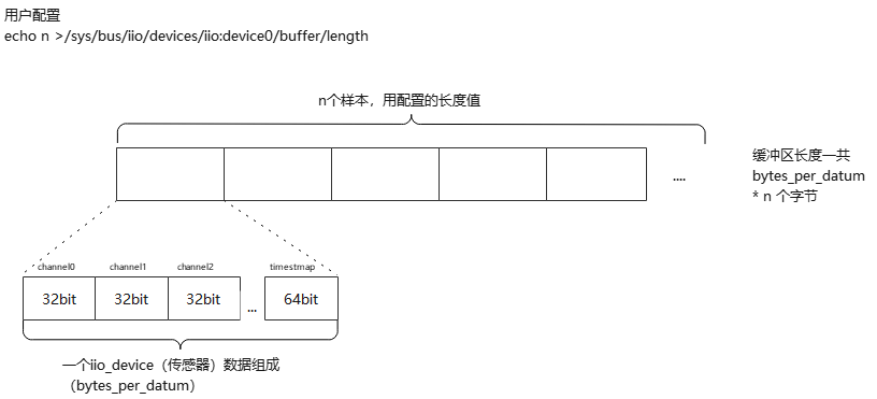
=====>copy_to_user 调用该接口,将数据从fifo缓冲区中拷贝给用户用户读取缓冲区数据由一个fifo对象管理,是一个先进先出的循环队列,主要由结构体struct __kfifo进行维护:
struct __kfifo {
    unsigned int    in;
    unsigned int    out;
    unsigned int    mask;
    unsigned int    esize;
    void        *data;
};
如下图是根据kfifo画出的示意图:
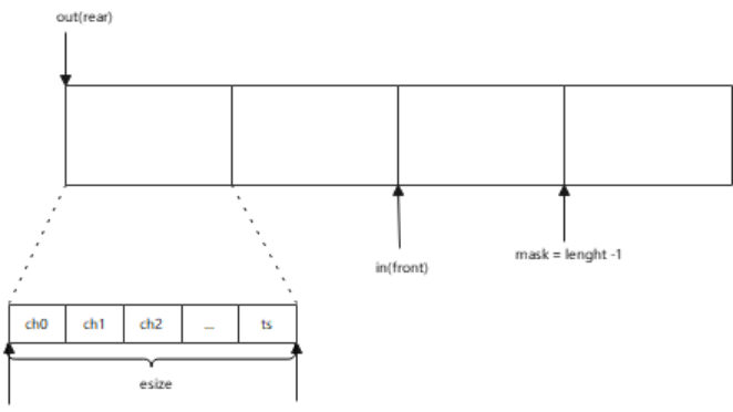
其中out和in相当于前后指针,esize是一个传感器所有通道值加时间戳(如果用户配置了时间戳),mask则是样本数的长度减一。当用户读取数据时,从out指针位置开始读,完成后out向前移动;当驱动塞数据到缓冲区时,in指针向前移动。
4.2.5.3 缓冲区申请关系过程
前面一直提到kfifo维护一个缓冲区,本小节分析该缓冲区大小计算和申请内存的时机。
缓冲区的申请时机,是在用户配置缓冲区使能的时候申请的,用户执行如下命令时(或者用户代码配置),驱动将调用sysfs绑定的接口进行初始化。
echo 1 > /sys/bus/iio/devices/iio:device0/buffer/enable
或者
    trig_fd = open(IIO_DEVICE_PATH "/buffer/enable", O_WRONLY);
    write(trig_fd, "1", 1);
    close(trig_fd);
同理,样本长度也可在用户层配置:
# 设置缓冲区大小为256个样本
echo 256 > /sys/bus/iio/devices/iio:device0/buffer/length
对应的,驱动初始化注册了buffer的sysfs回调,包含了enable/length和watermark:
__iio_device_register (drivers/iio/industrialio-core.c)
=>iio_buffers_alloc_sysfs_and_mask (drivers/iio/industrialio-buffer.c)
==>__iio_buffer_alloc_sysfs_and_mask (drivers/iio/industrialio-buffer.c)
static int __iio_buffer_alloc_sysfs_and_mask(struct iio_buffer *buffer,
                         struct iio_dev *indio_dev,
                         int index)
{
...
//iio_buffer_attrs 里实现了dev_attr_enable属性,enable即为上述应用配置的设备
    memcpy(attr, iio_buffer_attrs, sizeof(iio_buffer_attrs));
    if (!buffer->access->set_length)
        attr[0] = &dev_attr_length_ro.attr;//支持样本长度情况下同样配置属性
    if (buffer->access->flags & INDIO_BUFFER_FLAG_FIXED_WATERMARK)
        attr[2] = &dev_attr_watermark_ro.attr;//支持水位阈值配置
    if (buffer->attrs)
        memcpy(&attr[ARRAY_SIZE(iio_buffer_attrs)], buffer->attrs,
               sizeof(struct attribute *) * buffer_attrcount);
    buffer_attrcount += ARRAY_SIZE(iio_buffer_attrs);
    buffer->buffer_group.attrs = attr;//赋值关联到当前的iio buffer中
...
}
//如下是enable、length和watermark的属性配置
static DEVICE_ATTR(length, S_IRUGO | S_IWUSR, iio_buffer_read_length,
           iio_buffer_write_length);
static struct device_attribute dev_attr_length_ro = __ATTR(length,
    S_IRUGO, iio_buffer_read_length, NULL);
static DEVICE_ATTR(enable, S_IRUGO | S_IWUSR,
           iio_buffer_show_enable, iio_buffer_store_enable);
static DEVICE_ATTR(watermark, S_IRUGO | S_IWUSR,
           iio_buffer_show_watermark, iio_buffer_store_watermark);
static struct device_attribute dev_attr_watermark_ro = __ATTR(watermark,
    S_IRUGO, iio_buffer_show_watermark, NULL);
static DEVICE_ATTR(data_available, S_IRUGO,
        iio_dma_show_data_available, NULL);
static struct attribute *iio_buffer_attrs[] = {
    &dev_attr_length.attr,
    &dev_attr_enable.attr,
    &dev_attr_watermark.attr,
    &dev_attr_data_available.attr,
};
从上述可知,当用户对不同设备进行配置时,将调用到不同属性下绑定的回调。
enable回调申请缓冲区流程:
iio_buffer_store_enable  (drivers/iio/industrialio-buffer.c)
=>__iio_update_buffers
==>iio_buffer_request_update
===>request_update 该会调用在前面分析过,是access下的回调 kfifo_access_funcs
====>iio_request_update_kfifo  (drivers/iio/buffer/kfifo_buf.c)
=====>__iio_allocate_kfifo
======>__kfifo_alloc  (lib/kfifo.c)
int __kfifo_alloc(struct __kfifo *fifo, unsigned int size,
        size_t esize, gfp_t gfp_mask)
{
    size = roundup_pow_of_two(size);
//对fifo初始化
    fifo->in = 0;
    fifo->out = 0;
    fifo->esize = esize;
    if (size < 2) {
        fifo->data = NULL;
        fifo->mask = 0;
        return -EINVAL;
}
//申请数组内存,数组大小esize,数组数量size
    fifo->data = kmalloc_array(esize, size, gfp_mask);
...    fifo->mask = size - 1;
    return 0;
}
上面申请缓冲区流程中,使用了esize和size,其中esize是当前传感器所有数据大小(一个样本),而size则是用户配置的length样本数量,也就是说内存申请大小为size * esize个字节。
size是用户配置的length,根据前面分析,当用户配置length,sysfs接口iio_buffer_write_length被调用:
iio_buffer_write_length   (drivers/iio/industrialio-buffer.c)
==>set_length  该会调用在前面分析过,是access下的回调 kfifo_access_funcs
static int iio_set_length_kfifo(struct iio_buffer *r, unsigned int length)
{
    /* Avoid an invalid state */
    if (length < 2)//最小值2
        length = 2;
    if (r->length != length) {
        r->length = length;//赋值
        iio_mark_update_needed_kfifo(r);//更新缓冲区待更新标志
    }
    return 0;
}
同理watermark也一样,watermark是用户配置的最小触发阈值,当驱动缓冲区数量小此值时,将不会触发用户读取。
前面提到esize的值是一个样本值,在enable回调申请缓冲区流程中调用的iio_buffer_request_update接口,更新了esize的值:
iio_buffer_request_update
==>iio_buffer_update_bytes_per_datum
static void iio_buffer_update_bytes_per_datum(struct iio_dev *indio_dev,
    struct iio_buffer *buffer)
{
...
//这里计算每个通道和timesmap字节数量,即当前iio device支持的传感器所有通道数量+时间戳占用的字节数量,为一个样本
bytes = iio_compute_scan_bytes(indio_dev, buffer->scan_mask,buffer->scan_timestamp);
//该回调用在前面分析过,是access下的回调 kfifo_access_funcs
    buffer->access->set_bytes_per_datum(buffer, bytes);
}
下图大致总结了上述计算流程:
4.3 数据关系
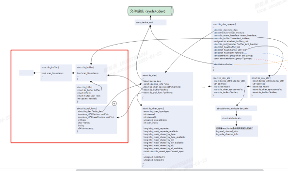
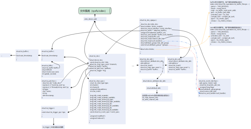
如下描绘IIO子系统中主要结构体数据之间的关系,以及数据是如何串联到提供给应用层的回调接口的。
struct iio_dev_opaque 作为IIO子系统整体管理结构体,在用户使用IIO子系统接口(devm_iio_device_alloc)申请内存时被分配,并向驱动用户返回了一个struct iio_dev结构体数据,每一个硬件传感器将实现生成一个struct iio_dev,对应着/sys/bus/iio/devices/iio:deviceX设备(理论上可以将一个硬件传感器实现成多个IIO device,但一般不会这么干,除非驱动开发者有特殊需求或者...头铁),该结构体管理着通道信息结构体struct iio_chan_spec。每个通道都会生成以struct iio_dev_attr 并加入struct iio_dev_opaque下的struct list_head channel_attr_list链表,struct iio_dev_attr下的attr成员里read/write则被赋值为iio_read_channel_info和iio_write_channel_info,两个接口是应用层调用read/write最终调用到驱动的接口。struct iio_dev_opaque下的cdev成员操作集被赋值为buffer和trigger的对上接口,驱动用户配置使能buffer/trigger模式时,应用用户将调用到这些操作集接口。最后通过cdev_device_add将struct iio_dev_opaqu下的chrdev和struct iio_dev下的dev注册到文件系统,生成对应的设备文件。
5 后记
本文大部分情况都在解释iio提供的sysfs和缓冲区触发两种模式流程,iio还有其他模式,在理解本文情况下,还能继续分析其他模式的源码。
6 附录
6.1 直接模式示例完整代码
#include <linux/iio/iio.h>
#include <linux/iio/sysfs.h>
#include <linux/iio/buffer.h>
#include <linux/iio/trigger_consumer.h>
#include <linux/iio/triggered_buffer.h>
#include <linux/platform_device.h>
#include <linux/platform_profile.h>
#include <linux/module.h>
#include <linux/kernel.h>
#include <linux/of.h>
#include <linux/of_graph.h>
#include <linux/of_platform.h>
#include <linux/of_device.h>

#define TEMP_NUM_CHANNELS 4 //温度传感器的通道数 1个温度通道 + 3 个加速度xyz通道
#define ANGL_NUM_CHANNELS 3 //陀螺仪传感器通道数 3个通道xyz
#define SAMPLE_SENSOR_TEMP 0 //温度传感器标识
#define SAMPLE_SENSOR_ANGL 1 //温度传感器标识

#define SAMPLE_TEMP_SCALE 326800000 //温度传感器的量程值

typedef struct sensor_config_ {
    int id;
    int *scale_sensor;
}sensor_config;

typedef struct iio_tlab_data_ {
    struct mutex lock;
    struct sensor_config_ *sensor;
    //control data
}iio_tlab_data;

/*
 * 陀螺仪分辨率
 */
static int angl_scale_sensor[] = {7629, 15258, 30517, 61035};

/*
 * 加速度计分辨率
 */
static int accel_scale_sensor[] = {61035, 122070, 244140, 488281};

#define SENSOR_CHAN_SPEC(type_, dind, mask) \
        { \
            .type = (type_), \
            .channel2 = (dind), \
            .info_mask_separate = (mask), \
            .address = 0, \
            .scan_index = 0, \
            .scan_type = { \
                .sign = 'u', \
                .realbits = 16, \
                .storagebits = 16, \
                .shift = 0, \
            }, \
            .modified = 1, \
        }

static const struct iio_chan_spec temp_sensor_channels[] = {
    {
        .type = IIO_TEMP,
        .channel = 0,
        .info_mask_separate = BIT(IIO_CHAN_INFO_RAW)|BIT(IIO_CHAN_INFO_SCALE),//    //支持读取原始值(IIO_CHAN_INFO_RAW),读取分别率(IIO_CHAN_INFO_SCALE)
        .address = 0,
        .scan_index = 0,
        .scan_type = {
            .sign = 'u',
            .realbits = 16,
            .storagebits = 16,
            .shift = 0,
        },
        .indexed = 1,
    },
    //支持读取原始值(IIO_CHAN_INFO_RAW),读取分别率(IIO_CHAN_INFO_SCALE),配置校准值(IIO_CHAN_INFO_CALIBBIAS)
    SENSOR_CHAN_SPEC(IIO_ACCEL, IIO_MOD_X, BIT(IIO_CHAN_INFO_RAW)|BIT(IIO_CHAN_INFO_SCALE)|BIT(IIO_CHAN_INFO_CALIBBIAS)),
    SENSOR_CHAN_SPEC(IIO_ACCEL, IIO_MOD_Y, BIT(IIO_CHAN_INFO_RAW)|BIT(IIO_CHAN_INFO_SCALE)|BIT(IIO_CHAN_INFO_CALIBBIAS)),
    SENSOR_CHAN_SPEC(IIO_ACCEL, IIO_MOD_Z, BIT(IIO_CHAN_INFO_RAW)|BIT(IIO_CHAN_INFO_SCALE)|BIT(IIO_CHAN_INFO_CALIBBIAS)),
};

static const struct iio_chan_spec angl_sensor_channels[] = {
    //支持读取原始值(IIO_CHAN_INFO_RAW),读取分别率(IIO_CHAN_INFO_SCALE),配置校准值(IIO_CHAN_INFO_CALIBBIAS)
    SENSOR_CHAN_SPEC(IIO_ANGL_VEL, IIO_MOD_X, BIT(IIO_CHAN_INFO_RAW)|BIT(IIO_CHAN_INFO_SCALE)|BIT(IIO_CHAN_INFO_CALIBBIAS)),
    SENSOR_CHAN_SPEC(IIO_ANGL_VEL, IIO_MOD_Y, BIT(IIO_CHAN_INFO_RAW)|BIT(IIO_CHAN_INFO_SCALE)|BIT(IIO_CHAN_INFO_CALIBBIAS)),
    SENSOR_CHAN_SPEC(IIO_ANGL_VEL, IIO_MOD_Z, BIT(IIO_CHAN_INFO_RAW)|BIT(IIO_CHAN_INFO_SCALE)|BIT(IIO_CHAN_INFO_CALIBBIAS)),
};

/*
  * @description     	: 读函数,当读取sysfs中的文件的时候最终此函数会执行,此函数里面会从传感器里面读取各种数据,然后上传给应用。
  * @param - indio_dev	: 设备控制对象
  * @param - chan   	: 通道描述对象
  * @param - val   		: 读取的值,如果是小数值的话,val是整数部分。
  * @param - val2   	: 读取的值,如果是小数值的话,val2是小数部分。
  * @param - mask   	: 掩码,如上述通道配置中IIO_CHAN_INFO_RAW、IIO_CHAN_INFO_SCALE...
  * @return				: 0<,成功;其他值:返回当前返回参数类型值形式。
*/
static int sensor_read_raw(struct iio_dev *indio_dev,
                                struct iio_chan_spec const *chan,
                                int *val, int *val2, long mask)
{
    struct iio_tlab_data_ *iio_pd;
    iio_pd = iio_priv(indio_dev);

    switch (mask) {
    case IIO_CHAN_INFO_RAW:{ //读取原始传感器值
        switch (chan->type)
        {
            case IIO_TEMP:
                *val = (chan->address == 0) ? 2500 : 3000; // 模拟温度值(0.25°C/0.30°C)
                return IIO_VAL_INT;
            case IIO_ACCEL:
                *val = chan->channel2 + 1; // 模拟加速度值
                return IIO_VAL_INT;
            case IIO_ANGL_VEL:
                *val = chan->channel2 + 1; // 模拟陀螺仪值
                return IIO_VAL_INT;
            default:
                break;
        }
    }
    case IIO_CHAN_INFO_SCALE:{
        switch (chan->type)
        {
            case IIO_TEMP://温度量程
                *val = SAMPLE_TEMP_SCALE/1000000;
                *val2 = SAMPLE_TEMP_SCALE%1000000;
                return IIO_VAL_INT_PLUS_MICRO;	/* 值为val+val2/1000000 */
            case IIO_ACCEL://加速度计分辨率
                mutex_lock(&iio_pd->lock);
                *val = 0;
                *val2 = iio_pd->sensor->scale_sensor[chan->channel2-1];// x:1 y:2 z:3
                mutex_unlock(&iio_pd->lock);
                return IIO_VAL_INT_PLUS_NANO;/* 值为val+val2/1000000000 */
            case IIO_ANGL_VEL://陀螺仪分辨率
                mutex_lock(&iio_pd->lock);
                *val = 0;
                *val2 = iio_pd->sensor->scale_sensor[chan->channel2-1];
                mutex_unlock(&iio_pd->lock);
                return IIO_VAL_INT_PLUS_NANO;/* 值为val+val2/1000000000 */
            default:
                break;
        }
    }
    default:
        return -EINVAL;
    }
}

/*
  * @description     	: 写函数,当向sysfs中的文件写数据的时候最终此函数会执行,一般在此函数里面设置传感器,比如量程等。
  * @param - indio_dev	: 设备控制对象
  * @param - chan   	: 通道描述对象
  * @param - val   		: 应用程序写入的值,如果是小数值的话,val是整数部分。
  * @param - val2   	: 应用程序写入的值,如果是小数值的话,val2是小数部分。
  * @return				: 0,成功;其他值为错误码
  */
static int sensor_write_raw(struct iio_dev *indio_dev,
    struct iio_chan_spec const *chan,
    int val, int val2, long mask)
{
    struct iio_tlab_data_ *iio_pd = iio_priv(indio_dev);
	int ret = 0;

	switch (mask) {
	case IIO_CHAN_INFO_SCALE:	/* 设置陀螺仪和加速度计的分辨率 */
		switch (chan->type) {
		case IIO_ANGL_VEL:		/* 设置陀螺仪 */
			mutex_lock(&iio_pd->lock);
			mutex_unlock(&iio_pd->lock);
			break;
		case IIO_ACCEL:			/* 设置加速度计 */
			mutex_lock(&iio_pd->lock);
			mutex_unlock(&iio_pd->lock);
			break;
		default:
			ret = -EINVAL;
			break;
		}
		break;
	case IIO_CHAN_INFO_CALIBBIAS:	/* 设置陀螺仪和加速度计的校准值*/
		switch (chan->type) {
		case IIO_ANGL_VEL:		/* 设置陀螺仪校准值 */
			mutex_lock(&iio_pd->lock);
			mutex_unlock(&iio_pd->lock);
			break;
		case IIO_ACCEL:			/* 加速度计校准值 */
			mutex_lock(&iio_pd->lock);
			mutex_unlock(&iio_pd->lock);
			break;
		default:
			ret = -EINVAL;
			break;
		}
		break;
	default:
		ret = -EINVAL;
		break;
	}
	return ret;
}

static const struct iio_info sensor_info = {
    .read_raw = sensor_read_raw,
    .write_raw = sensor_write_raw,
};

static int sensor_probe(struct platform_device *pdev)
{
    struct iio_dev *indio_dev;
    int ret;
    struct sensor_config_ *sc;
    struct iio_tlab_data_ *iio_pd;

    printk("%s:%d\n", __func__, __LINE__);

	sc = of_device_get_match_data(&pdev->dev);
	if (!sc) {
        printk("get driver data fail\n");
		return -ENODEV;
    }

    indio_dev = devm_iio_device_alloc(&pdev->dev, sizeof(*iio_pd));
    if (!indio_dev)
        return -ENOMEM;
    iio_pd = iio_priv(indio_dev);
    iio_pd->sensor = sc;
    printk("sensor type: %s\n", sc->id == SAMPLE_SENSOR_TEMP?"temp":"angl");

    if(sc->id == SAMPLE_SENSOR_TEMP) {
        indio_dev->name = "virtual_temp_sensor";
        indio_dev->channels = temp_sensor_channels;
        indio_dev->num_channels = TEMP_NUM_CHANNELS;
    } else if(sc->id == SAMPLE_SENSOR_ANGL){
        indio_dev->name = "virtual_angl_sensor";
        indio_dev->channels = angl_sensor_channels;
        indio_dev->num_channels = ANGL_NUM_CHANNELS;
    } else {
        return -ENODEV;
    }
    indio_dev->info = &sensor_info;
    indio_dev->modes = INDIO_DIRECT_MODE;//直接读取模型,提供sysfs

    ret = devm_iio_device_register(&pdev->dev, indio_dev);
    if (ret < 0)
        return ret;
    printk("%s:%d register %s successfully\n", __func__, __LINE__, sc->id == SAMPLE_SENSOR_TEMP?"temp":"angl");

    return 0;
}

static struct sensor_config_ temp_sensor_data = {
    .id = SAMPLE_SENSOR_TEMP,
    .scale_sensor = accel_scale_sensor
};

static struct sensor_config_ angl_sensor_data = {
    .id = SAMPLE_SENSOR_ANGL,
    .scale_sensor = angl_scale_sensor
};

static const struct of_device_id iio_lab_match[] = {
	{
		.compatible = "virtual,temp_sensor",
		.data = &temp_sensor_data,
	},{
		.compatible = "virtual,angl_sensor",
		.data = &angl_sensor_data,
	},
	{}
};
MODULE_DEVICE_TABLE(of, iio_lab_match);

static struct platform_driver sensor_driver = {
    .probe = sensor_probe,
    .driver = {
        .name = "sensors",
        .of_match_table = of_match_ptr(iio_lab_match),
    },
};

module_platform_driver(sensor_driver);
MODULE_LICENSE("GPL");
MODULE_AUTHOR("TT");
MODULE_DESCRIPTION("iio demo");
应用层:
/*************************************************************************
 * File Name: iio_app.c
 * Author: xxx
 * Mail: xxx@xxx
 * Created Time: 2025年04月17日 星期四 14时59分24秒
 ************************************************************************/

#include <stdio.h>
#include <stdlib.h>
#include <fcntl.h>
#include <unistd.h>
#include <error.h>
 #include <string.h>

int main(int argc, char *argv[])
{
    char path[100] = {0};
    int fd = -1;
    char buffer[20] = {0};

	printf("iio sample app\n");
    // 读取通道0的原始值
    snprintf(path, sizeof(path), "/sys/bus/iio/devices/iio:device0/in_temp0_raw");
    fd = open(path, O_RDONLY);
    if(fd<0) {
        perror("/sys/bus/iio/devices/iio:device0/in_temp0_raw");
        return -1;
    }
    read(fd, buffer, sizeof(buffer));
    printf("Channel0 Raw: %s\n", buffer);
    close(fd);

    // 读取比例因子
    memset(buffer, 0, sizeof(buffer));
    memset(path, 0, sizeof(path));
    snprintf(path, sizeof(path), "/sys/bus/iio/devices/iio:device0/in_temp0_scale");
    fd = open(path, O_RDONLY);
    if(fd<0) {
        perror("/sys/bus/iio/devices/iio:device0/in_temp0_scale");
        return -1;
    }
    read(fd, buffer, sizeof(buffer));
    printf("Scale: %s\n", buffer);
    close(fd);

    return 0;
}
6.2 触发模式示例完整代码
#include <linux/iio/iio.h>
#include <linux/iio/sysfs.h>
#include <linux/iio/buffer.h>
#include <linux/iio/trigger_consumer.h>
#include <linux/iio/triggered_buffer.h>
#include <linux/iio/trigger.h>
#include <linux/iio/events.h>

#include <linux/platform_device.h>
#include <linux/platform_profile.h>
#include <linux/module.h>
#include <linux/kernel.h>
#include <linux/of.h>
#include <linux/of_graph.h>
#include <linux/of_platform.h>
#include <linux/of_device.h>
#include <linux/hrtimer.h>
#include <linux/ktime.h>
#include <linux/debugfs.h>

#define NUM_CHANNELS 4
#define DRV_NAME "iio_temp_sensor"

typedef struct sensor_config_ {
    int id;
    int *scale_sensor;
}sensor_config;

typedef struct temtemp_fb_data_ {
    int temp_val[3];
    unsigned long long timestamp;
}temp_fb_data;

typedef struct iio_tlab_data_ {
    struct mutex lock;
    struct iio_trigger *trigger;
    struct hrtimer soft_timer;
    struct device	*dev;
    unsigned int sampling_freq;
    /*32bit * 3channel + 64bit timesmap*/
    __be32 buffer[5];
    //control data
}iio_tlab_data;

#define CHAN_SPEC(type_, index, mask, scind) \
        { \
            .type = (type_), \
            .channel = (index), \
            .info_mask_separate = BIT(mask), \
            .address = 0, \
            .scan_index = (scind), \
            .scan_type = { \
                .sign = 's', \
                .realbits = 32, \
                .storagebits = 32, \
                .endianness = IIO_CPU, \
            }, \
            .indexed = 1, \
        }

static const struct iio_chan_spec temp_sensor_channels[] = {
    CHAN_SPEC(IIO_TEMP, 0, IIO_CHAN_INFO_RAW, 0),
    CHAN_SPEC(IIO_TEMP, 1, IIO_CHAN_INFO_RAW, 1),
    CHAN_SPEC(IIO_TEMP, 2, IIO_CHAN_INFO_RAW, 2),
    IIO_CHAN_SOFT_TIMESTAMP(3), // 时间戳通道
};

static int temp_sensor_read_raw(struct iio_dev *indio_dev,
                                struct iio_chan_spec const *chan,
                                int *val, int *val2, long mask)
{
    switch (mask) {
    case IIO_CHAN_INFO_RAW:
        *val = (chan->address == 0) ? 2500 : 3000; // 模拟温度值(0.25°C/0.30°C)
        return IIO_VAL_INT;
    case IIO_CHAN_INFO_SCALE:
        *val = 83;
        return IIO_VAL_INT;
    default:
        return -EINVAL;
    }
}

static enum hrtimer_restart soft_trigger_func(struct hrtimer *timer)
{
    struct iio_tlab_data_ *tlab_p = container_of(timer, struct iio_tlab_data_, soft_timer);

    // dev_info(tlab_p->dev, "%s:%d\n", __func__, __LINE__);

    hrtimer_forward_now(timer, ktime_set(0, 100000000)); // 2Hz触发
    iio_trigger_poll(tlab_p->trigger);

    return HRTIMER_RESTART;
}

static int soft_buffer_preenable(struct iio_dev *indio_dev)
{
    struct iio_tlab_data_ *tlab_p = iio_priv(indio_dev);
    dev_info(tlab_p->dev, "%s:%d\n", __func__, __LINE__);

    hrtimer_start(&tlab_p->soft_timer, ktime_set(0, 0), HRTIMER_MODE_REL);
    return 0;
}

static int soft_buffer_predisable(struct iio_dev *indio_dev)
{
    struct iio_tlab_data_ *tlab_p = iio_priv(indio_dev);
    dev_info(tlab_p->dev, "%s:%d\n", __func__, __LINE__);

    hrtimer_cancel(&tlab_p->soft_timer);

    return 0;
}

static const struct iio_buffer_setup_ops soft_buffer_ops = {
    .preenable = soft_buffer_preenable,
    .predisable = soft_buffer_predisable,
};

static IIO_CONST_ATTR(sampling_frequency_available, "4 2 1 0.5 0.25");

static struct attribute *tmp006_attributes[] = {
	&iio_const_attr_sampling_frequency_available.dev_attr.attr,
	NULL
};

static const struct attribute_group tmp006_attribute_group = {
	.attrs = tmp006_attributes,
};

static const struct iio_info temp_sensor_info = {
    .read_raw = temp_sensor_read_raw,
    .attrs = &tmp006_attribute_group,
};

/* 触发器属性操作:频率配置 */
static ssize_t sampling_frequency_store(struct device *dev,
    struct device_attribute *attr,
    const char *buf, size_t len)
{
    struct iio_trigger *trig = to_iio_trigger(dev);
    struct iio_tlab_data_ *tlab_p = iio_trigger_get_drvdata(trig);
    unsigned int freq;

    if (kstrtou32(buf, 10, &freq)) {
        return -EINVAL;
    }

    tlab_p->sampling_freq = freq;
    return len;
}

static ssize_t sampling_frequency_show(struct device *dev,
     struct device_attribute *attr,
     char *buf)
{
    struct iio_trigger *trig = to_iio_trigger(dev);
    struct iio_tlab_data_ *tlab_p = iio_trigger_get_drvdata(trig);

    return sprintf(buf, "%u\n", tlab_p->sampling_freq);
}

static IIO_DEV_ATTR_SAMP_FREQ(S_IWUSR | S_IRUGO,
    sampling_frequency_show,
    sampling_frequency_store);

static struct attribute *temp_trigger_attrs[] = {
    &iio_dev_attr_sampling_frequency.dev_attr.attr,
    NULL,
};

static const struct attribute_group temp_trigger_attr_group = {
	.attrs = temp_trigger_attrs,
};

static const struct attribute_group *temp_trigger_attr_groups[] = {
    &temp_trigger_attr_group,
    NULL,
};

static const struct iio_trigger_ops temp_trigger_ops = {
    .set_trigger_state = NULL, /* 由sysfs触发器管理状态 */
};

/* 触发器上半部(中断上下文) */
irqreturn_t iio_pollfunc(int irq, void *p)
{
    struct iio_tlab_data_ *tlab_p = iio_priv(p);
    dev_info(tlab_p->dev, "%s:%d\n", __func__, __LINE__);

    // tlab_p->timestamp = iio_get_time_ns(p);

    return IRQ_WAKE_THREAD;
}

/*
* 模拟读取硬件数据接口
*/
int read_adc_channel(int channel)
{
    static int channel0 = 7;
    static int channel1 = 8;
    static int channel2 = 9;

    return channel == 0?(channel0+1):(channel == 1?(channel1+1):(channel2+1));
}

/* 触发器下半部(内核线程上下文) */
irqreturn_t iio_trigger_handler(int irq, void *p)
{
    const struct iio_poll_func *pf = p;
    struct iio_dev *indio_dev = pf->indio_dev;
    struct iio_tlab_data_ *tlab_p = iio_priv(indio_dev);
    struct temtemp_fb_data_ *val = (struct temtemp_fb_data_ *)tlab_p->buffer;

    if(!tlab_p) {
        printk("null error\n");
        return IRQ_HANDLED;
    }

    mutex_lock(&tlab_p->lock);
    /* 模拟从硬件读取数据 */
    val->temp_val[0] = read_adc_channel(0);
    val->temp_val[1] = read_adc_channel(1);
    val->temp_val[2] = read_adc_channel(2);
    val->timestamp = iio_get_time_ns(indio_dev);
    /* 推送数据到缓冲区 */
    iio_push_to_buffers_with_timestamp(indio_dev, tlab_p->buffer, val->timestamp);
    // iio_push_to_buffers(indio_dev, tlab_p->buffer);
    /* 完成触发处理 */
    iio_trigger_notify_done(indio_dev->trig);

    mutex_unlock(&tlab_p->lock);

    return IRQ_HANDLED;
}

static int temp_sensor_probe(struct platform_device *pdev)
{
    struct iio_dev *indio_dev;
    int ret;
    struct iio_tlab_data_ *tlab_p;
    struct device	*dev = &pdev->dev;

    dev_info(dev, "%s:%d\n", __func__, __LINE__);

    indio_dev = devm_iio_device_alloc(&pdev->dev, sizeof(*tlab_p));
    if (!indio_dev)
        return -ENOMEM;
    tlab_p = iio_priv(indio_dev);
    mutex_init(&tlab_p->lock);
    tlab_p->dev = dev;

    indio_dev->name = DRV_NAME;
    indio_dev->channels = temp_sensor_channels;
    indio_dev->num_channels = NUM_CHANNELS;
    indio_dev->info = &temp_sensor_info;
    indio_dev->modes = INDIO_BUFFER_TRIGGERED;//触发模式

    /* 创建硬件触发器 */
    tlab_p->trigger = iio_trigger_alloc(&pdev->dev, "hrtimer-trig-%s", DRV_NAME);
    if (!tlab_p->trigger)
        return -ENOMEM;
    iio_trigger_set_drvdata(tlab_p->trigger, tlab_p);
    tlab_p->trigger->ops = &temp_trigger_ops;
    tlab_p->trigger->dev.groups = temp_trigger_attr_groups;
    ret = iio_trigger_register(tlab_p->trigger);
    if (ret) {
        iio_trigger_free(tlab_p->trigger);
        return ret;
    }
    indio_dev->trig = iio_trigger_get(tlab_p->trigger);

    ret = iio_triggered_buffer_setup(indio_dev,
        NULL,//上半部,这里记录时间戳
        &iio_trigger_handler, //下半部,处理缓冲区数据
        NULL);//使用默认的缓冲区

    ret = devm_iio_device_register(&pdev->dev, indio_dev);
    if (ret < 0)
        return ret;

    hrtimer_init(&tlab_p->soft_timer, CLOCK_MONOTONIC, HRTIMER_MODE_REL);
    tlab_p->soft_timer.function  = soft_trigger_func;
    hrtimer_start(&tlab_p->soft_timer, ktime_set(0, 500000000), HRTIMER_MODE_REL);
    dev_info(dev, "%s:%d successfully\n", __func__, __LINE__);

    return 0;
}

static struct sensor_config_ temp_data = {
    .id = 1
};

static const struct of_device_id iio_lab_match[] = {
	{
		.compatible = "virtual,temp_sensor",
		.data = &temp_data,
	},
	{}
};
MODULE_DEVICE_TABLE(of, iio_lab_match);

static struct platform_driver temp_sensor_driver = {
    .probe = temp_sensor_probe,
    .driver = {
        .name = DRV_NAME,
        .of_match_table = of_match_ptr(iio_lab_match),
    },
};

module_platform_driver(temp_sensor_driver);
MODULE_LICENSE("GPL");
MODULE_AUTHOR("TT");
MODULE_DESCRIPTION("iio demo");
应用层:
#include <stdio.h>
#include <fcntl.h>
#include <unistd.h>
#include <sys/ioctl.h>
#include <string.h>

#define CHANNEL_NUM 3
#define ALIGN_8(x) (((x) + 7) & ~7)
#define CHANNEL_DATA_BUFFER_LEN ALIGN_8(CHANNEL_NUM*4)

#define IIO_DEVICE_PATH "/sys/bus/iio/devices/iio:device0"
#define TRIGGER_PATH "/sys/bus/iio/devices/trigger0"
typedef struct temtemp_fb_data_ {
    int temp_val;
    unsigned int timestamp;
}temp_fb_data;

int main() {
    int fd, ret;
    char buf[CHANNEL_DATA_BUFFER_LEN + 8] = {0};
    temp_fb_data fdat;

    /* 设置hrtimer触发 */
    int trig_fd = open(IIO_DEVICE_PATH "/scan_elements/in_temp0_en", O_WRONLY);
    write(trig_fd, "1", 1);
    close(trig_fd);

    trig_fd = open(IIO_DEVICE_PATH "/buffer/length", O_WRONLY);
    write(trig_fd, "256", 3);
    close(trig_fd);

    trig_fd = open(IIO_DEVICE_PATH "/scan_elements/in_timestamp_en", O_WRONLY);
    write(trig_fd, "1", 1);
    close(trig_fd);

    trig_fd = open(IIO_DEVICE_PATH "/buffer/enable", O_WRONLY);
    write(trig_fd, "1", 1);
    close(trig_fd);


    /* 配置采样频率(单位:Hz) */
    int freq_fd = open(TRIGGER_PATH "/sampling_frequency", O_WRONLY);
    if(freq_fd < 0) {
        perror("sampling_frequency");
    } else {
        write(freq_fd, "10", 2);
    }
    close(freq_fd);

    /* 打开字符设备读取数据 */
    fd = open("/dev/iio:device0", O_RDONLY);
    if (fd < 0) {
        perror("Failed to open device");
        return 1;
    }

    while (1) {
        ssize_t len = read(fd, buf, sizeof(buf));
        if (len >= 0) {

            int *raw_temp = (int *)buf;
            for(int i=0;i<CHANNEL_NUM;i++) {
                printf("channel%d:%d°C ", i, raw_temp[i]);
            }
            unsigned long long *ts = (unsigned long long *)(buf+sizeof(buf)-8);
            printf("timesmap:%lluns\n", ts[0]);
        }
        usleep(500000); // 100ms间隔
    }

    close(fd);
    return 0;
}

/*
#!/bin/bash

# 1. 启用通道0和1
echo 1 > /sys/bus/iio/devices/iio:device0/scan_elements/in_temp0_en
echo 1 > /sys/bus/iio/devices/iio:device0/scan_elements/in_temp1_en

# 2. 设置缓冲区大小为256个样本
echo 256 > /sys/bus/iio/devices/iio:device0/buffer/length

# 3. 启用缓冲区
echo 1 > /sys/bus/iio/devices/iio:device0/buffer/enable

# 4. 设置sysfs触发器(假设已加载iio-trig-sysfs驱动)
echo 0 > /sys/devices/iio_sysfs_trigger/add_trigger
echo "sysfstrig0" > /sys/bus/iio/devices/trigger0/name
echo "sysfstrig0" > /sys/bus/iio/devices/iio:device0/trigger/current_trigger

# 5. 开始数据采集
echo 1 > /sys/bus/iio/devices/trigger0/trigger_now

# 6. 读取缓冲区数据(持续采集)
cat /dev/iio:device0 | hexdump -C

# 7. 清理操作
echo 0 > /sys/bus/iio/devices/iio:device0/buffer/enable

*/


 1091
1091

 被折叠的 条评论
为什么被折叠?
被折叠的 条评论
为什么被折叠?
 到【灌水乐园】发言


