


目录
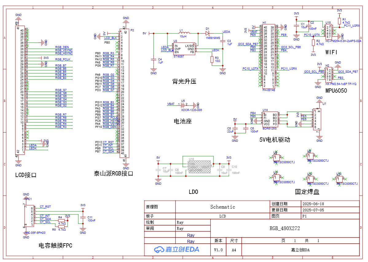
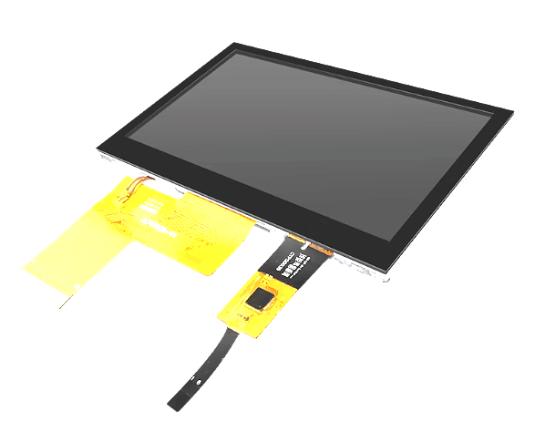
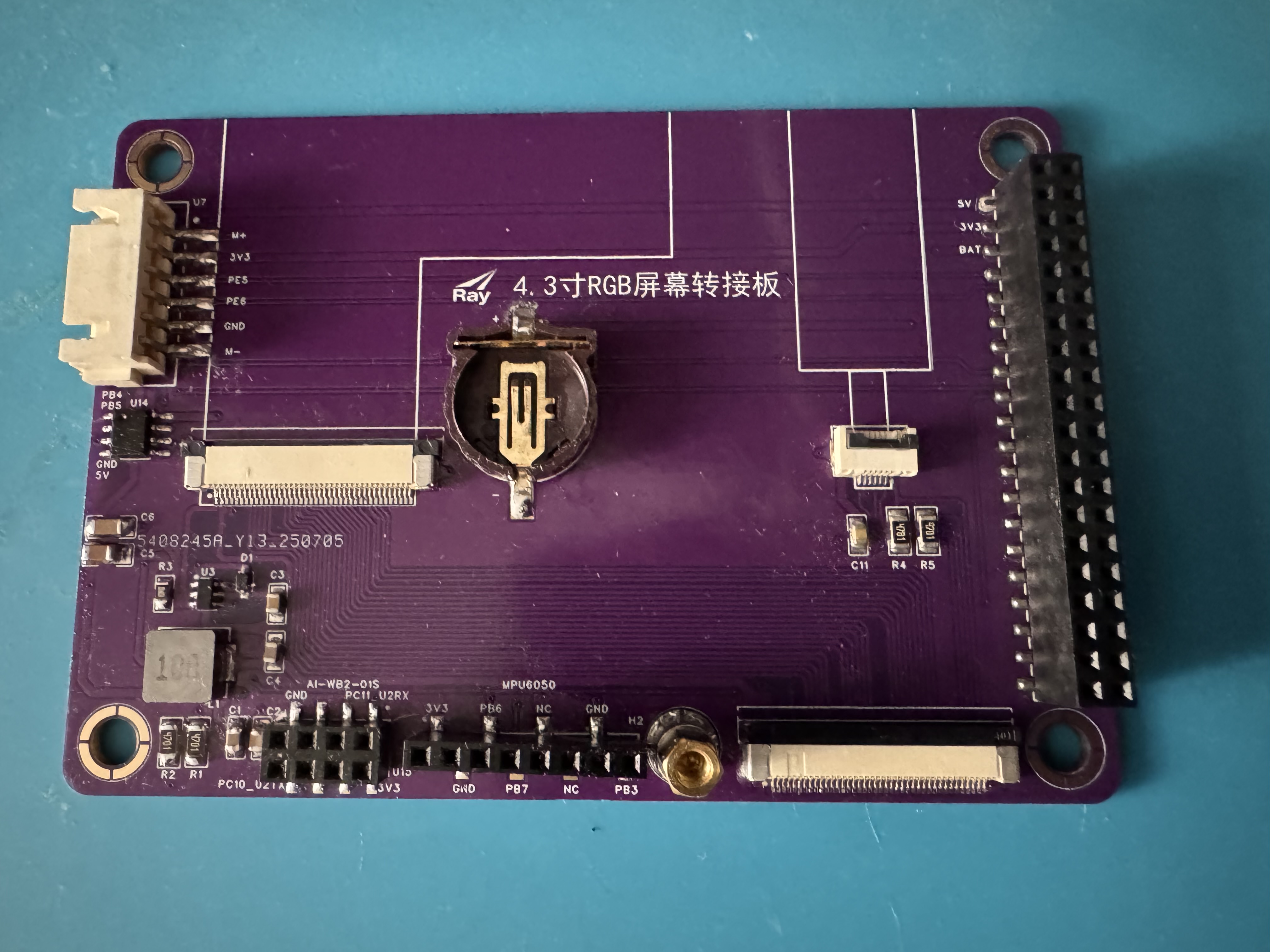
手头有一个梁山派,于是淘了块4.3寸480*272的裸屏,画了转接板,移植了LVGL。
梁山派的MCU是GD32F470,虽然库函数写法上和STM32不一样,但基本思路还是大同小异。现将移植中的主要过程记录下来备忘。
1.拷贝工程代码
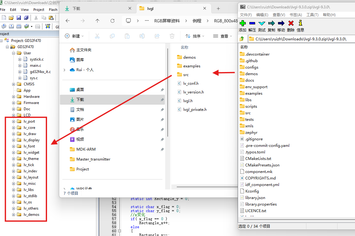
1)首先从github上拉下最新的9.3版本代码,拷贝到新建的LVGL根目录。根目录下只需要保留lv_conf_template.h,lv_version.h,lvgl.h和lv_private.h四个文件以及src、expamles和demos三个目录
2)把lv_conf_template.h改名为lv_conf.h,example目录仅需保存porting子目录中的文件,src目录所有文件保留,demos目录可要可不要。
3)打开lv_conf.h,把#if 0改为#if 1,其余地方没有特别需要改动的地方。
4)导入头文件路径“/LVGL”、“/LVGL/lvgl”、“/LVGL/lvgl/src”、“/LVGL/lvgl/examples/porting”
keil工程结构对应如下图所示。
上述步骤完成后编译一下,应该会有很多警告,但不会有错误。
2.配置屏幕输出
1)把lv_port_disp_template.c/h文件中的#if 0改为#if 1。
2)导入屏幕驱动头文件,例如我的是#include "lcd.h"。
3)在static void disp_init(void)函数中导入屏幕初始化语句,例如我的是lcd_disp_config();
4)配置图形缓冲模式。我选择的是方式二双缓冲,缓冲数组的大小为MY_DISP_HOR_RES * 136 * BYTE_PER_PIXEL,即半个屏幕。我也试过选择第三种全屏双缓冲模式,提示内存不够。
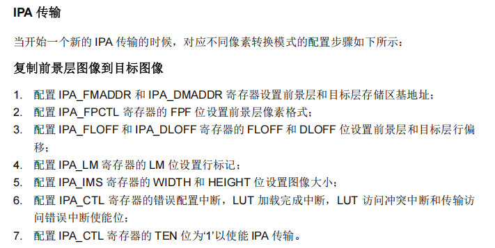
5)配置打点函数。这一步最为关键,我同时写了启动IPA(GD32下的DMA2D)和不启动IPA的方式。
IPA的配置说明GD32的官方指南里写的还是比较详细的,选用复制前景层图像到目标图像的配置步骤即可。
static void disp_flush(lv_display_t * disp_drv, const lv_area_t * area, uint8_t * px_map)
{
	uint16_t *pixel_buf = (uint16_t *)px_map;
    if(disp_flush_enabled) {

		#define USE_IPA
		#ifndef USE_IPA
        /*不启用IPA*/
        int32_t x;
        int32_t y;
        for(y = area->y1; y <= area->y2; y++) {
            for(x = area->x1; x <= area->x2; x++) {
                tli_draw_point(x,y,*pixel_buf);
                pixel_buf++;
            }
        }

		#else
        /*启用IPA*/
		tli_ipa_lvgl_fill(area->x1,area->y1,area->x2,area->y2,pixel_buf);
		#endif
    }

    lv_display_flush_ready(disp_drv);
}

/**********************************************************
 * 函 数 名 称:tli_ipa_fill
 * 函 数 功 能:IPA作为LVGL打点函数
**********************************************************/
void tli_ipa_lvgl_fill(uint16_t sx,uint16_t sy,uint16_t ex,uint16_t ey,uint16_t* color_p)
{
	uint16_t timeout=0;

	rcu_periph_clock_enable(RCU_IPA);

	IPA_CTL &= ~(1 << 0);                                                     //失能IPA
	IPA_FMADDR = (uint32_t)color_p;                                           //配置IPA_FMADDR寄存器设置前景层存储区基地址
	IPA_DMADDR = (uint32_t)ltdc_lcd_framebuf0[0] + 2 * (LCD_WIDTH * sy + sx); //配置IPA_DMADDR 寄存器设置目标层存储区基地址
	IPA_FPCTL = FOREGROUND_PPF_RGB565;                                        //配置IPA_FPCTL 寄存器的 FPF 位设置前景层像素格式
	IPA_FLOFF = 0;                                                            //配置IPA_FLOFF寄存器的FLOFF位设置前景层行偏移
	IPA_DLOFF = LCD_WIDTH - (ex-sx + 1);                                      //配置IPA_DLOFF寄存器的DLOFF位设置目标层行偏移
    IPA_IMS = (uint32_t)((ex - sx + 1) << 16) | (uint32_t)(ey -sy + 1);       //配置IPA_IMS 寄存器的 WIDTH 和 HEIGHT 位设置图像大小
    IPA_CTL |= (1 << 0);                                                      //使能IPA
    /* 等待数据传输完成 */
    while (IPA_CTL & IPA_CTL_TEN)
    {
        if (timeout++ >= 0XFFFF)
            break;
    }
	IPA_INTC|=IPA_INTF_FTFIF;
}
3.配置触摸
1)把lv_port_indev_template.c/h文件中的#if 0改为#if 1。
2)导入触摸驱动头文件,例如我的是#include "gt9xxx.h"。
3)屏蔽与touchpad无关的代码,需要自己插入的代码很少,主要如下。
/*------------------
 * Touchpad
 * -----------------*/

/*Initialize your touchpad*/
static void touchpad_init(void)
{
    /*Your code comes here*/
	tp_dev.init();
}

/*Return true is the touchpad is pressed*/
static bool touchpad_is_pressed(void)
{
    /*Your code comes here*/
	tp_dev.scan(0);
	if(tp_dev.sta & TP_PRES_DOWN)
	{
		return true;
	}

    return false;
}

/*Get the x and y coordinates if the touchpad is pressed*/
static void touchpad_get_xy(int32_t * x, int32_t * y)
{
    /*Your code comes here*/

    (*x) = tp_dev.x[0];
    (*y) = tp_dev.y[0];
}
我的屏幕用的触摸芯片为GT911,通信方式为IIC。要说一下GD32的硬件IIC代码实现和软件IIC相比一点也不简单。我都实现了,最终还是觉得软件IIC更为直观。特别是读取函数,GD32硬件IIC的实现方式非常繁琐,按照官方的示例代码,需要分为读取1个字节、2个字节和3个及以上字节三种情况。
uint8_t g_gt_tnum = 5;      /* 默认支持的触摸屏点数(5点触摸) */

#ifndef USE_HARD_IIC

/**
 * @brief       向gt9xxx写入一次数据
 * @param       reg : 起始寄存器地址
 * @param       buf : 数据缓缓存区
 * @param       len : 写数据长度
 * @retval      0, 成功; 1, 失败;
 */
uint8_t gt9xxx_wr_reg(uint16_t reg, uint8_t *buf, uint8_t len)
{
    uint8_t i;
    uint8_t ret = 0;
    CT_IIC_Start();
    CT_IIC_Send_Byte(GT9XXX_CMD_WR);    /* 发送写命令 */
    CT_IIC_Wait_Ack();
    CT_IIC_Send_Byte(reg >> 8);         /* 发送高8位地址 */
    CT_IIC_Wait_Ack();
    CT_IIC_Send_Byte(reg & 0XFF);       /* 发送低8位地址 */
    CT_IIC_Wait_Ack();

    for (i = 0; i < len; i++)
    {
        CT_IIC_Send_Byte(buf[i]);       /* 发数据 */
        ret = CT_IIC_Wait_Ack();

        if (ret)break;
    }

    CT_IIC_Stop();                      /* 产生一个停止条件 */
    return ret;
}

#else

uint8_t gt9xxx_wr_reg(uint16_t reg, uint8_t *buf, uint8_t len)
{
	uint8_t i;
	 /* wait until I2C bus is idle */
    while(i2c_flag_get(I2C0, I2C_FLAG_I2CBSY));

    /* send a start condition to I2C bus */
    i2c_start_on_bus(I2C0);

    /* wait until SBSEND bit is set */
    while(!i2c_flag_get(I2C0, I2C_FLAG_SBSEND));

    /* send slave address to I2C bus*/
    i2c_master_addressing(I2C0, I2C0_SLAVE_ADDRESS7, I2C_TRANSMITTER);

    /* wait until ADDSEND bit is set*/
    while(!i2c_flag_get(I2C0, I2C_FLAG_ADDSEND));

    /* clear ADDSEND bit */
    i2c_flag_clear(I2C0, I2C_FLAG_ADDSEND);

	/* send a memory byte */
	i2c_data_transmit(I2C0, reg >> 8);
	/* wait until the transmit data buffer is empty */
    while(!i2c_flag_get(I2C0, I2C_FLAG_TBE));
	i2c_data_transmit(I2C0, reg & 0XFF);
	/* wait until the transmit data buffer is empty */
    while(!i2c_flag_get(I2C0, I2C_FLAG_TBE));

    for(i = 0; i < len; i++) {
        /* send a data byte */
        i2c_data_transmit(I2C0, buf[i]);
        /* wait until the transmission data register is empty*/
        while(!i2c_flag_get(I2C0, I2C_FLAG_TBE));
    }
    /* send a stop condition to I2C bus*/
    i2c_stop_on_bus(I2C0);
    /* wait until stop condition generate */
    while(I2C_CTL0(I2C0) & I2C_CTL0_STOP);

	return 0;
}

#endif

#ifndef USE_HARD_IIC
/**
 * @brief       从gt9xxx读出一次数据
 * @param       reg : 起始寄存器地址
 * @param       buf : 数据缓缓存区
 * @param       len : 读数据长度
 * @retval      无
 */
void gt9xxx_rd_reg(uint16_t reg, uint8_t *buf, uint8_t len)
{
    uint8_t i;
    CT_IIC_Start();
    CT_IIC_Send_Byte(GT9XXX_CMD_WR);                        /* 发送写命令 */
    CT_IIC_Wait_Ack();
    CT_IIC_Send_Byte(reg >> 8);                             /* 发送高8位地址 */
    CT_IIC_Wait_Ack();
    CT_IIC_Send_Byte(reg & 0XFF);                           /* 发送低8位地址 */
    CT_IIC_Wait_Ack();
    CT_IIC_Start();
    CT_IIC_Send_Byte(GT9XXX_CMD_RD);                        /* 发送读命令 */
    CT_IIC_Wait_Ack();

    for (i = 0; i < len; i++)
    {
        buf[i] = CT_IIC_Read_Byte(i == (len - 1) ? 0 : 1);  /* 读取数据 */
    }

    CT_IIC_Stop();                                          /* 产生一个停止条件 */
}

#else

void gt9xxx_rd_reg(uint16_t reg, uint8_t *buf, uint8_t len)
{
	uint8_t i;


	/*****I.Write Part*****/
	/* wait until I2C bus is idle */
    while(i2c_flag_get(I2C0, I2C_FLAG_I2CBSY));

    /* send a start condition to I2C bus */
    i2c_start_on_bus(I2C0);

    /* wait until SBSEND bit is set */
    while(!i2c_flag_get(I2C0, I2C_FLAG_SBSEND));

    /* send slave address to I2C bus*/
    i2c_master_addressing(I2C0, I2C0_SLAVE_ADDRESS7, I2C_TRANSMITTER);

    /* wait until ADDSEND bit is set*/
    while(!i2c_flag_get(I2C0, I2C_FLAG_ADDSEND));

    /* clear ADDSEND bit */
    i2c_flag_clear(I2C0, I2C_FLAG_ADDSEND);

	/* send a memory byte */
	i2c_data_transmit(I2C0, reg >> 8);
	/* wait until the transmit data buffer is empty */
    while(!i2c_flag_get(I2C0, I2C_FLAG_TBE));
	i2c_data_transmit(I2C0, reg & 0XFF);
	/* wait until the transmit data buffer is empty */
    while(!i2c_flag_get(I2C0, I2C_FLAG_TBE));
    /* send a stop condition to I2C bus*/
    i2c_stop_on_bus(I2C0);
    /* wait until stop condition generate */
    while(I2C_CTL0(I2C0) & I2C_CTL0_STOP);
	/* enable acknowledge */
    i2c_ack_config(I2C0, I2C_ACK_ENABLE);

	/*****II.Read Part*****/
	 /* wait until I2C bus is idle */
    while(i2c_flag_get(I2C0, I2C_FLAG_I2CBSY));

    /* send a start condition to I2C bus */
    i2c_start_on_bus(I2C0);

    /* wait until SBSEND bit is set */
    while(!i2c_flag_get(I2C0, I2C_FLAG_SBSEND));

    /* send slave address to I2C bus*/
    i2c_master_addressing(I2C0, I2C0_SLAVE_ADDRESS7, I2C_RECEIVER);

    /* wait until ADDSEND bit is set*/
    while(!i2c_flag_get(I2C0, I2C_FLAG_ADDSEND));

	if(len==1){
		/* N=1,reset ACKEN bit before clearing ADDRSEND bit */
		i2c_ack_config(I2C0, I2C_ACK_DISABLE);
		/* clear ADDSEND bit */
		i2c_flag_clear(I2C0, I2C_FLAG_ADDSEND);
		/* N=1,send stop condition after clearing ADDRSEND bit */
		i2c_stop_on_bus(I2C0);
		/* wait until the RBNE bit is set */
		while(!i2c_flag_get(I2C0, I2C_FLAG_RBNE));
		/* read a data from I2C_DATA */
		buf[0] = i2c_data_receive(I2C0);
		/* wait until stop condition generate */
		while(I2C_CTL0(I2C0) & I2C_CTL0_STOP);
		/* enable acknowledge */
		i2c_ack_config(I2C0, I2C_ACK_ENABLE);
	}else if(len==2){
		/* send a NACK for the next data byte which will be received into the shift register */
		i2c_ackpos_config(I2C0, I2C_ACKPOS_NEXT);
		/* wait until I2C bus is idle */
		while(i2c_flag_get(I2C0, I2C_FLAG_I2CBSY));
		/* send a start condition to I2C bus */
		i2c_start_on_bus(I2C0);
		/* wait until SBSEND bit is set */
		while(!i2c_flag_get(I2C0, I2C_FLAG_SBSEND));
		/* send slave address to I2C bus */
		i2c_master_addressing(I2C0, I2C0_SLAVE_ADDRESS7, I2C_RECEIVER);
		/* disable ACK before clearing ADDSEND bit */
		i2c_ack_config(I2C0, I2C_ACK_DISABLE);
		/* wait until ADDSEND bit is set */
		while(!i2c_flag_get(I2C0, I2C_FLAG_ADDSEND));
		/* clear ADDSEND bit */
		i2c_flag_clear(I2C0, I2C_FLAG_ADDSEND);
		/* Wait until the last data byte is received into the shift register */
		while(!i2c_flag_get(I2C0, I2C_FLAG_BTC));
		/* wait until the RBNE bit is set */
		while(!i2c_flag_get(I2C0, I2C_FLAG_RBNE));
		/* read a data from I2C_DATA */
		buf[0] = i2c_data_receive(I2C0);
		/* wait until the RBNE bit is set */
		while(!i2c_flag_get(I2C0, I2C_FLAG_RBNE));
		/* read a data from I2C_DATA */
		buf[1] = i2c_data_receive(I2C0);
		/* send a stop condition */
		i2c_stop_on_bus(I2C0);
		/* wait until stop condition generate */
		while(I2C_CTL0(I2C0) & I2C_CTL0_STOP);
		i2c_ackpos_config(I2C0, I2C_ACKPOS_CURRENT);
		/* enable acknowledge */
		i2c_ack_config(I2C0, I2C_ACK_ENABLE);
	}
	else{
		/* clear ADDSEND bit */
		i2c_flag_clear(I2C0, I2C_FLAG_ADDSEND);

		for(i = 0; i < len; i++) {
			if(i==len-3)
			{
				/* wait until the second last data byte is received into the shift register */
				while(!i2c_flag_get(I2C0, I2C_FLAG_BTC));
				/* disable acknowledge */
				i2c_ack_config(I2C0, I2C_ACK_DISABLE);
			}
			/* wait until the RBNE bit is set */
			while(!i2c_flag_get(I2C0, I2C_FLAG_RBNE));
			/* read a data from I2C_DATA */
			buf[i] = i2c_data_receive(I2C0);
		}
		/* send a stop condition to I2C bus*/
		i2c_stop_on_bus(I2C0);
		/* wait until stop condition generate */
		while(I2C_CTL0(I2C0) & I2C_CTL0_STOP);
		/* enable acknowledge */
		i2c_ack_config(I2C0, I2C_ACK_ENABLE);
	}
}

#endif
4.配置时基和收尾
1)配置1ms为单位的基本定时器,并在定时器文件中添加“lvgl.h”头文件
2)在定时器中断回调函数中添加语句lv_tick_inc(1)
3) 在main函数的while循环中加入lv_timer_handler(); delay_1ms(5);
接下来就可以在main文件中添加必要的头文件、初始化语句和测试代码了。主要包括:
#include "lvgl.h"
#include "lv_port_disp_template.h"
#include "lv_port_indev_template.h"
#include "lv_demo_widgets.h"
lv_init();
lv_port_disp_init();
lv_port_indev_init();
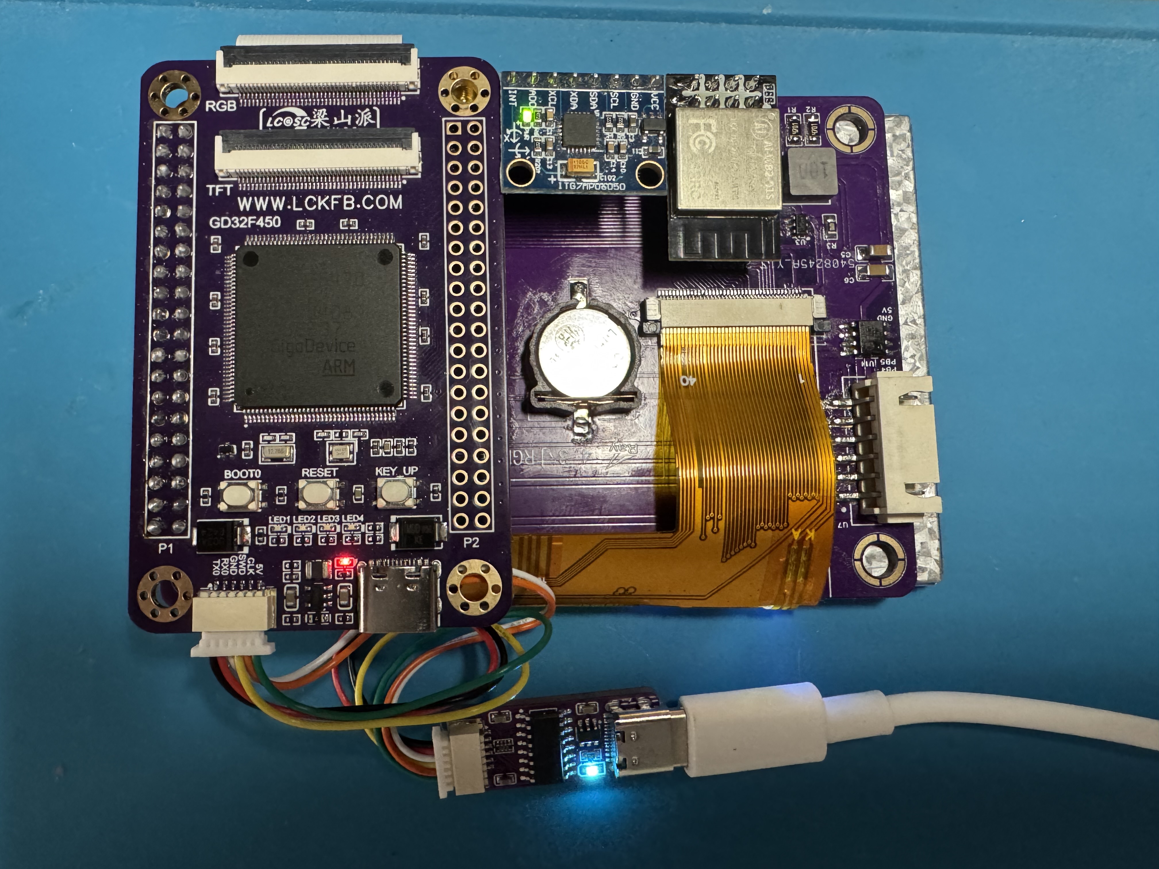
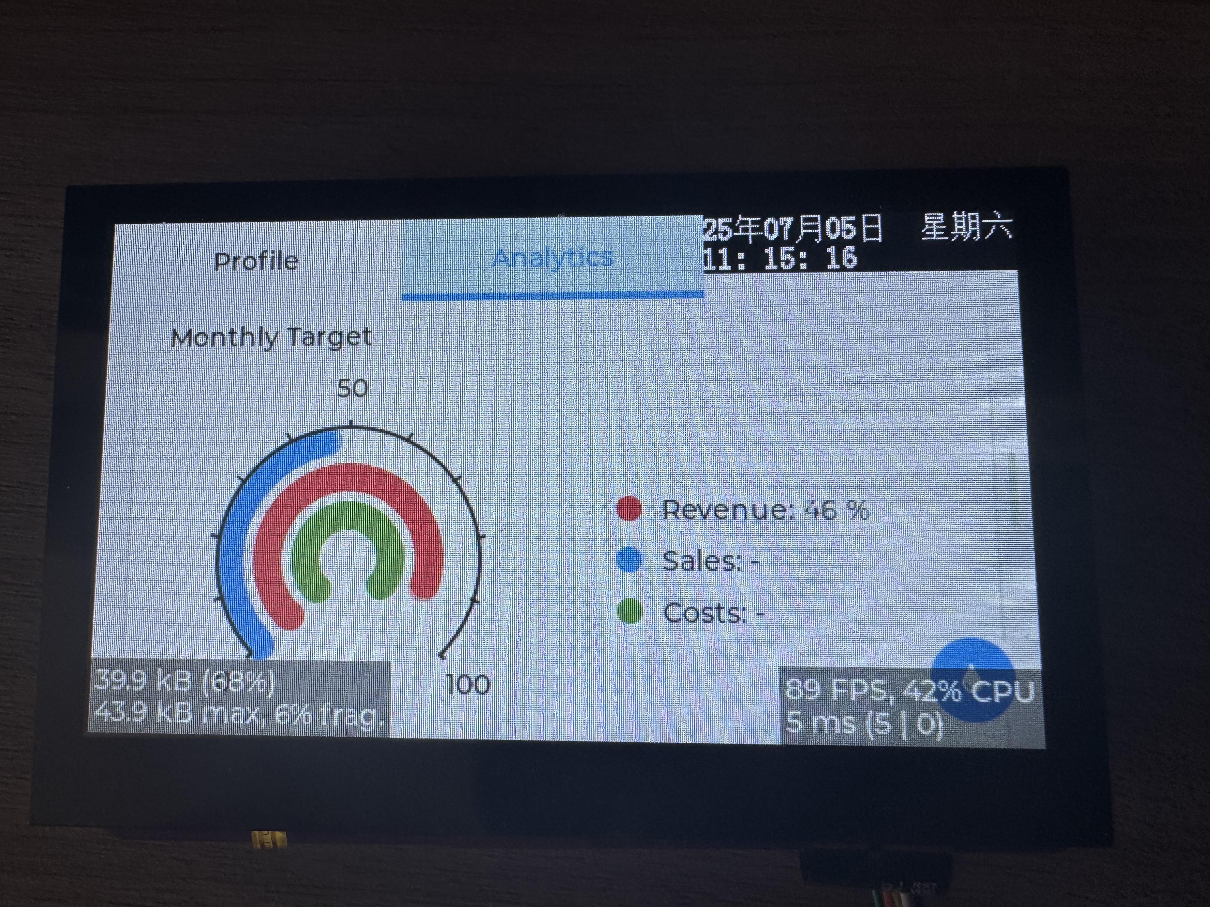
lv_demo_widgets();总体来说移植难度不大,感觉和8.x版本的移植步骤基本一样。最后上效果图。


 998
998

 被折叠的 条评论
为什么被折叠?
被折叠的 条评论
为什么被折叠?
 到【灌水乐园】发言


