


 本文详细描述了一个实验,涉及RIP路由协议配置、GRE隧道、PPP认证(PAP和CHAP)、HDLC封装以及NAT转换,旨在实现私有网络互通和公私网通信的实验步骤。
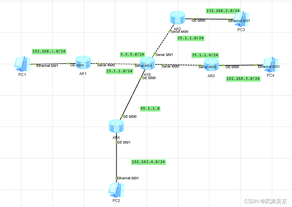
实验拓扑
实验要求
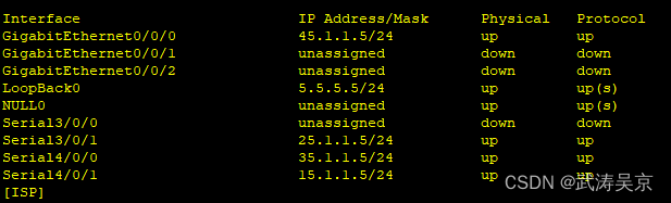
1、R5为ISP,只能进行IP地址配置,其所有地址均配为公有IP地址;
2、R1和R5间使用PPP的PAP认证,R5为主认证方;
R2与R5之间使用ppp的CHAP认证,R5为主认证方;
R3与R5之间使用HDLC封装;
3、R1、R2、R3构建一个MGRE环境,R1为中心站点,R1、R4间为点到点的GRE;
4、整个私有网络基本RIP全网可达;
5、所有PC设置私有IP为源IP,可以访问R5环回,达到全网通。
实验步骤
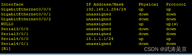
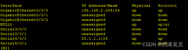
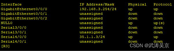
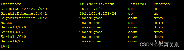
配置接口ip地址
配置公网通,内外网出口配置缺省路由指向公网
[R1]ip route-static 0.0.0.0 0 15.1.1.5
[R2]ip route-static 0.0.0.0 0 25.1.1.5
[R3]ip route-static 0.0.0.0 0 35.1.1.5
[R4]ip route-static 0.0.0.0 0 45.1.1.5
完成R1和R5之间的PAP认证,R5为主认证方。
[ISP]aaa
[ISP-aaa]local-user tg privilege level 15 password cipher tg12345
[ISP-aaa]local-user tg service-type ppp
[ISP]int Serial 4/0/1 连接被认证方的端口
[ISP-Serial4/0/1]ppp authentication-mode pap
[R1]int Serial 4/0/0
[R1-Serial4/0/0]ppp pap local-user tg password cipher tg12345
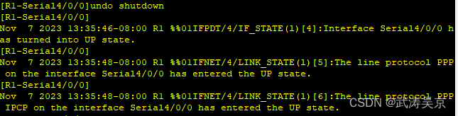
测试关闭闭在开启 R1 和 R5 的 PPP 链路,检查验证是否能够通过。
完成R2与R5之间的chap认证,R5为主认证方
[ISP]int s3/0/1
[ISP-Serial3/0/1]ppp authentication-mode chap
[R2]int s4/0/0
[R2-Serial4/0/0]ppp chap user tg
[R2-Serial4/0/0]ppp chap password cipher tg12345
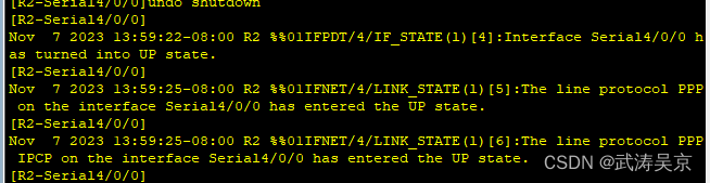
测试关闭在开启 R2 和 R5 的 PPP 链路,检查验证是否能够通过
完成R3与R5之间为HDLC封装。
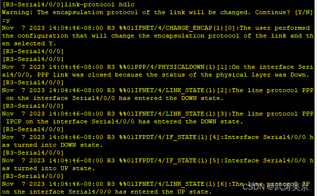
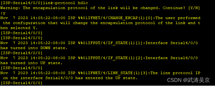
中心站点配置
[R1]int t0/0/0
[R1-Tunnel0/0/0]ip add 10.1.2.1 24
[R1-Tunnel0/0/0]tunnel-protocol gre p2mp
[R1-Tunnel0/0/0]source 15.1.1.1
Nov 7 2023 19:39:25-08:00 R1 %%01IFNET/4/LINK_STATE(l)[0]:The line protocol IP
on the interface Tunnel0/0/0 has entered the UP state.
[R1-Tunnel0/0/0]nhrp network-id 100
[R1-Tunnel0/0/0]nhrp entry multicast dynamic
分支站点配置[R2-Serial4/0/0]int t0/0/0
[R2-Tunnel0/0/0]ip add 10.1.2.2 24
[R2-Tunnel0/0/0]tunnel-protocol gre p2mp
[R2-Tunnel0/0/0]source Serial 4/0/0
Nov 7 2023 19:41:00-08:00 R2 %%01IFNET/4/LINK_STATE(l)[8]:The line protocol IP
on the interface Tunnel0/0/0 has entered the UP state.
[R2-Tunnel0/0/0]nhrp network-id 100
[R2-Tunnel0/0/0]nhrp entry 10.1.2.1 15.1.1.1 register
[R3]int t0/0/0
[R3-Tunnel0/0/0]ip add 10.1.2.3 24
[R3-Tunnel0/0/0]tunnel-protocol gre p2mp
[R3-Tunnel0/0/0]source Serial 4/0/0
Nov 7 2023 19:42:35-08:00 R3 %%01IFNET/4/LINK_STATE(l)[0]:The line protocol IP
on the interface Tunnel0/0/0 has entered the UP state.
[R3-Tunnel0/0/0]nhrp network-id 100
[R3-Tunnel0/0/0]nhrp entry 10.1.2.1 15.1.1.1 register
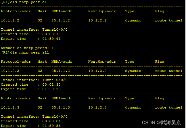
测试
传递私网路由,配置rip协议
[R1]rip 1
[R1-rip-1]undo summary
[R1-rip-1]v 2
[R1-rip-1]network 192.168.1.0
[R1-rip-1]network 10.0.0.0
[R1-Tunnel0/0/0]undo rip split-horizon
[R2]rip
[R2-rip-1]un summary
[R2-rip-1]v 2
[R2-rip-1]network 192.168.2.0
[R2-rip-1]network 10.0.0.0
[R3]rip
[R3-rip-1]un summary
[R3-rip-1]network 192.168.3.0
[R3-rip-1]network 10.0.0.0
配置R1,R4间的GRE
[R4]int t0/0/1
[R4-Tunnel0/0/1]ip add 10.1.1.2 24
[R4-Tunnel0/0/1]tunnel-protocol gre
[R4-Tunnel0/0/1]source 45.1.1.4
[R4-Tunnel0/0/1]description 15.1.1.1
[R1]int t0/0/1
[R1-Tunnel0/0/1]ip add 10.1.1.1 24
[R1-Tunnel0/0/1]tunnel-protocol gre
[R1-Tunnel0/0/1]source 15.1.1.1
[R1-Tunnel0/0/1]description 45.1.1.4
配置R4rip协议传递私网路由
[R4]rip 1
[R4-rip-1]undo summary
[R4-rip-1]v 2
[R4-rip-1]network 192.168.4.0
[R4-rip-1]network 10.0.0.0
测试
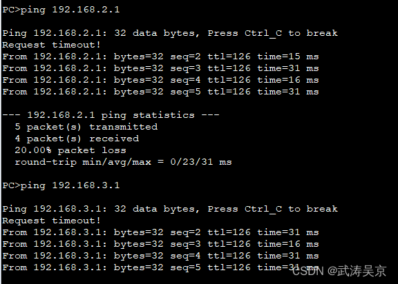
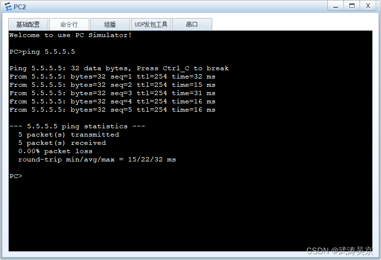
所有pc设置私有IP为源IP,可以访问R5环回
配置nat将私网流量转化到公网上
[R1]acl 2000
[R1-acl-basic-2000]rule permit source 192.168.1.0 0.0.0.255
[R1]int s4/0/0
[R1-Serial4/0/0]nat outbound 2000
[R2]acl 2000
[R2-acl-basic-2000]rule permit source 192.168.2.0 0.0.0.255
[R2]int s4/0/0
[R2-Serial4/0/0]nat outbound 2000
[R3]acl 2000
[R3-acl-basic-2000]rule permit source 192.168.3.0 0.0.0.255
[R3]int s4/0/0
[R3-Serial4/0/0]nat outbound 2000
[R4]acl 2000
[R4-acl-basic-2000]rule permit source 192.168.4.0 0.0.0.255
[R4]int g0/0/0
[R4-GigabitEthernet0/0/0]nat outbound 2000
测试


 被折叠的 条评论
为什么被折叠?
被折叠的 条评论
为什么被折叠?
 到【灌水乐园】发言


