


 文章详细介绍了如何将STM32F10x芯片的寄存器操作通过宏定义和结构体封装,提高代码可读性和可移植性。首先,通过定义基地址和结构体,将直接的地址操作转换为结构体成员访问。然后,创建了端口置位和复位的函数,简化了对GPIO引脚的操作。最后,通过枚举类型和结构体初始化,进一步封装了GPIO配置,使得配置过程更加直观且易于在不同项目中复用。

(程序在文章结尾)
直接从地址编程到库封装
#include "stm32f10x.h"int main(void){//使能时钟* (unsigned int *) 0X4002 1018 |=(1<<3);//配置CRL寄存器 配置IO口输出模式* (unsigned int *) 0X4001 0C00 |=((1)<<(4*0));//配置ODR寄存器* (unsigned int *) 0X4001 0C0C &=^(1<<0);}
寄存器映射
#define PERIPH_BASE ((unsigned int)0x40000000) //基地址#define APB1PERIPH_BASE PERIPH_BASE //APB1及地址#define APB2PERIPH_BASE (PERIPH_BASE + 0x10000000)//APB2基地址#define AHBPERIPH_BASE (PERIPH_BASE + 0x20000000)//AHB基地址#define RCC_BASE (AHBPERIPH_BASE+0x1000) //RCC基地址#define GPIOB_BASE (APB2PERIPH_BASE+0X0C00) //GPIOB基地址#define RCC_APB2ENR (unsigned int*)(RCC_BASE + 0x18) //APB2使能#define GPIOB_CRL (unsigned int*)(RCC_BASE + 0x00) //CRL寄存器基地址#define GPIOB_CRH (unsigned int*)(RCC_BASE + 0x04) //CRH寄存器基地址#define GPIOB_ODR (unsigned int*)(RCC_BASE + 0x0c) //ODR寄存器基地址
所以
//使能时钟
* (unsigned int *) 0X4002 1018 |=(1<<3);
修改为
RCC_APB2ENR |=(1<<3);
//配置CRL寄存器 配置IO口输出模式
* (unsigned int *) 0X4001 0C00 |=((1)<<(4*0));
修改为
GPIOB_CRL |=((1)<<(4*0));
//配置ODR寄存器
* (unsigned int *) 0X4001 0C0C &=^(1<<0) ;
修改为
GPIOB_ODR &=^(1<<0);
寄存器映射 代码可读性增强
#include "stm32f10x.h"int main(void){//使能时钟RCC_APB2ENR |=(1<<3);GPIOB_CRL |=((1)<<(4*0));//配置ODR寄存器GPIOB_ODR &=^(1<<0);}
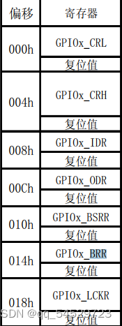
1)封装
#define PERIPH_BASE ((unsigned int)0x40000000) //基地址#define APB1PERIPH_BASE PERIPH_BASE //APB1及地址#define APB2PERIPH_BASE (PERIPH_BASE + 0x10000000)//APB2基地址#define AHBPERIPH_BASE (PERIPH_BASE + 0x20000000)//AHB基地址#define RCC_BASE (AHBPERIPH_BASE+0x1000) //RCC基地址#define GPIOB_BASE (APB2PERIPH_BASE+0X0C00) //GPIOB基地址#define RCC_APB2ENR (unsigned int*)(RCC_BASE + 0x18) //APB2使能typedef unsigned int uint32_ttypedef unsigned short uint16_t//通过结构体访问寄存器//利用结构体连续访问内存的特点,每次偏移4个字节,正好对应偏移量typedef shurt{uint32_t CRL; //CRL偏移量为0uint32_t CRH; //CRH偏移量为0X04uint32_t IDR; //IDR偏移量为0X08uint32_t ODR; //ODR偏移量为0X0Cuint32_t BSRR; //BSRR偏移量为0X10uint32_t BRR; //BRR偏移量为0X14uint32_t LCKR; //LCKR偏移量为0X18}GPIO_Typedef;typedef struct{uint32_t CR;uint32_t CFGR;uint32_t CIR;uint32_t APB2RSTR;uint32_t APB1RSTR;uint32_t AHBENR;uint32_t APB2ENR;uint32_t APB1ENR;uint32_t BDCR;uint32_t CSR;}RCC_TypeDef;#define RCC ((RCC_TypeDef*)RCC_BASE)#define GPIOB ((GPIO_Typedef*)GPIO_BASE) //令GPIO_Typedef的基地址为GPIO_BASE地址
通过以上程序将地址指向以下内存
#include "stm32f10x.h"int main(void){//使能时钟RCC_APB2ENR |=(1<<3);GPIOB_CRL |=((1)<<(4*0));//配置ODR寄存器GPIOB_ODR &=^(1<<0);}可修改为#include "stm32f10x.h"int main(void){//使能时钟RCC_APB2ENR |=(1<<3);//配置IO口输出GPIOB->CRL |=((1)<<(4*0));//配置ODR寄存器GPIOB->ODR &=^(1<<0);};
2)端口置位复位函数编写
void GPIO_SetBits(GPIO_TypeDef *GPIOx,uint16_t GPIO_Pin){GPIOx->BSRR |= GPIO_Pin;}void GPIO_ResetBits( GPIO_TypeDef *GPIOx,uint16_t GPIO_Pin ){GPIOx->BRR |= GPIO_Pin;}void GPIO_Init(GPIO_TypeDef* GPIOx, GPIO_InitTypeDef* GPIO_InitStruct)
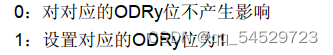 BSRR寄存器可以对ODR寄存器进行置一
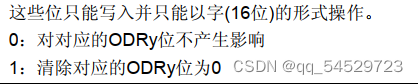 BRR寄存器可以对ODR寄存器进行置0
//宏定义#define GPIO_Pin_0 ((uint16_t)0x0001) /*!< 选择Pin0 */ //(00000000 00000001)b#define GPIO_Pin_1 ((uint16_t)0x0002) /*!< 选择Pin1 */ //(00000000 00000010)b#define GPIO_Pin_2 ((uint16_t)0x0004) /*!< 选择Pin2 */ //(00000000 00000100)b#define GPIO_Pin_3 ((uint16_t)0x0008) /*!< 选择Pin3 */ //(00000000 00001000)b#define GPIO_Pin_4 ((uint16_t)0x0010) /*!< 选择Pin4 */ //(00000000 00010000)b#define GPIO_Pin_5 ((uint16_t)0x0020) /*!< 选择Pin5 */ //(00000000 00100000)b#define GPIO_Pin_6 ((uint16_t)0x0040) /*!< 选择Pin6 */ //(00000000 01000000)b#define GPIO_Pin_7 ((uint16_t)0x0080) /*!< 选择Pin7 */ //(00000000 10000000)b#define GPIO_Pin_8 ((uint16_t)0x0100) /*!< 选择Pin8 */ //(00000001 00000000)b#define GPIO_Pin_9 ((uint16_t)0x0200) /*!< 选择Pin9 */ //(00000010 00000000)b#define GPIO_Pin_10 ((uint16_t)0x0400) /*!< 选择Pin10 */ //(00000100 00000000)b#define GPIO_Pin_11 ((uint16_t)0x0800) /*!< 选择Pin11 */ //(00001000 00000000)b#define GPIO_Pin_12 ((uint16_t)0x1000) /*!< 选择Pin12 */ //(00010000 00000000)b#define GPIO_Pin_13 ((uint16_t)0x2000) /*!< 选择Pin13 */ //(00100000 00000000)b#define GPIO_Pin_14 ((uint16_t)0x4000) /*!< 选择Pin14 */ //(01000000 00000000)b#define GPIO_Pin_15 ((uint16_t)0x8000) /*!< 选择Pin15 */ //(10000000 00000000)b#define GPIO_Pin_All ((uint16_t)0xFFFF) /*!< 选择全部引脚*/ //(11111111 11111111)b
main函数修改为
#include "stm32f10x.h"int main(void){RCC->APB2ENR |= ( (1) << 3 );// 配置IO口为输出GPIOB->CRL &= ~( (0x0f) << (4*0) );GPIOB->CRL |= ( (1) << (4*0) );GPIO_SetBits(GPIOB,GPIO_Pin_1);GPIO_ResetBits( GPIOB,GPIO_Pin_1 );};
3)完全封装
typedef enum{GPIO_Speed_10MHz = 1, // 10MHZ (01)bGPIO_Speed_2MHz, // 2MHZ (10)bGPIO_Speed_50MHz // 50MHZ (11)b}GPIOSpeed_TypeDef;typedef enum{ GPIO_Mode_AIN = 0x0, // 模拟输入 (0000 0000)bGPIO_Mode_IN_FLOATING = 0x04, // 浮空输入 (0000 0100)bGPIO_Mode_IPD = 0x28, // 下拉输入 (0010 1000)bGPIO_Mode_IPU = 0x48, // 上拉输入 (0100 1000)bGPIO_Mode_Out_OD = 0x14, // 开漏输出 (0001 0100)bGPIO_Mode_Out_PP = 0x10, // 推挽输出 (0001 0000)bGPIO_Mode_AF_OD = 0x1C, // 复用开漏输出 (0001 1100)bGPIO_Mode_AF_PP = 0x18 // 复用推挽输出 (0001 1000)b}GPIOMode_TypeDef;typedef struct{uint16_t GPIO_Pin;uint16_t GPIO_Speed;uint16_t GPIO_Mode;}GPIO_InitTypeDef;void GPIO_SetBits(GPIO_TypeDef *GPIOx,uint16_t GPIO_Pin);void GPIO_ResetBits( GPIO_TypeDef *GPIOx,uint16_t GPIO_Pin );void GPIO_Init(GPIO_TypeDef* GPIOx, GPIO_InitTypeDef* GPIO_InitStruct);//(GPIO_Iint()函数过于复杂,会用即可)
main函数修改为
#include "stm32f10x.h"int main(void){GPIO_InitTypeDef GPIO_InitStructure;// 打开 GPIOB 端口的时钟RCC->APB2ENR |= ( (1) << 3 );GPIO_InitStructure.GPIO_Pin = GPIO_Pin_0;GPIO_InitStructure.GPIO_Mode = GPIO_Mode_Out_PP;GPIO_InitStructure.GPIO_Speed = GPIO_Speed_50MHz;GPIO_Init(GPIOB, &GPIO_InitStructure);GPIO_SetBits(GPIOB,GPIO_Pin_0);GPIO_ResetBits( GPIOB,GPIO_Pin_0 );};
4)提高程序可移植性
可以多采用宏定义,方便修改,因人而异#define LED_G_GPIO_PORT GPIOB#define LED_G_GPIO_CLK_ENABLE (RCC->APB2ENR |= ( (1) << 3 ))#define LED_G_GPIO_PIN GPIO_Pin_1
程序如下
链接:
百度网盘 请输入提取码
提取码:qhq2
--来自百度网盘超级会员V3的分享


 1648
1648

 被折叠的 条评论
为什么被折叠?
被折叠的 条评论
为什么被折叠?
 到【灌水乐园】发言


