


第一次调试西门子PLC,接到一个流水线的分箱项目。
项目需求:通过扫描器扫不同的码,进入对应的箱体(总共7个箱体)。
项目主要使用:西门子PLC1200,威纶通屏幕,西克扫描器(485通讯)。
编程软件:博途2016,labview2021。
因为有多年的LabView编程经验这边主要记录博途的配置。
- 首先配置普通的网口通讯,
- 再在普通的基础上写一套modbusTCP通讯,
- 用labview自带的modbusTCP模块进行通讯。
- 最后再写一个简单的手机APP控制PLC。
点开博途软件组网自己对应的PLC,我这里使用了一个路由器可以通过wifi与PLC相连
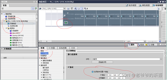
配置好IP地址
跳到编程界面,选择开放式通讯下的模块
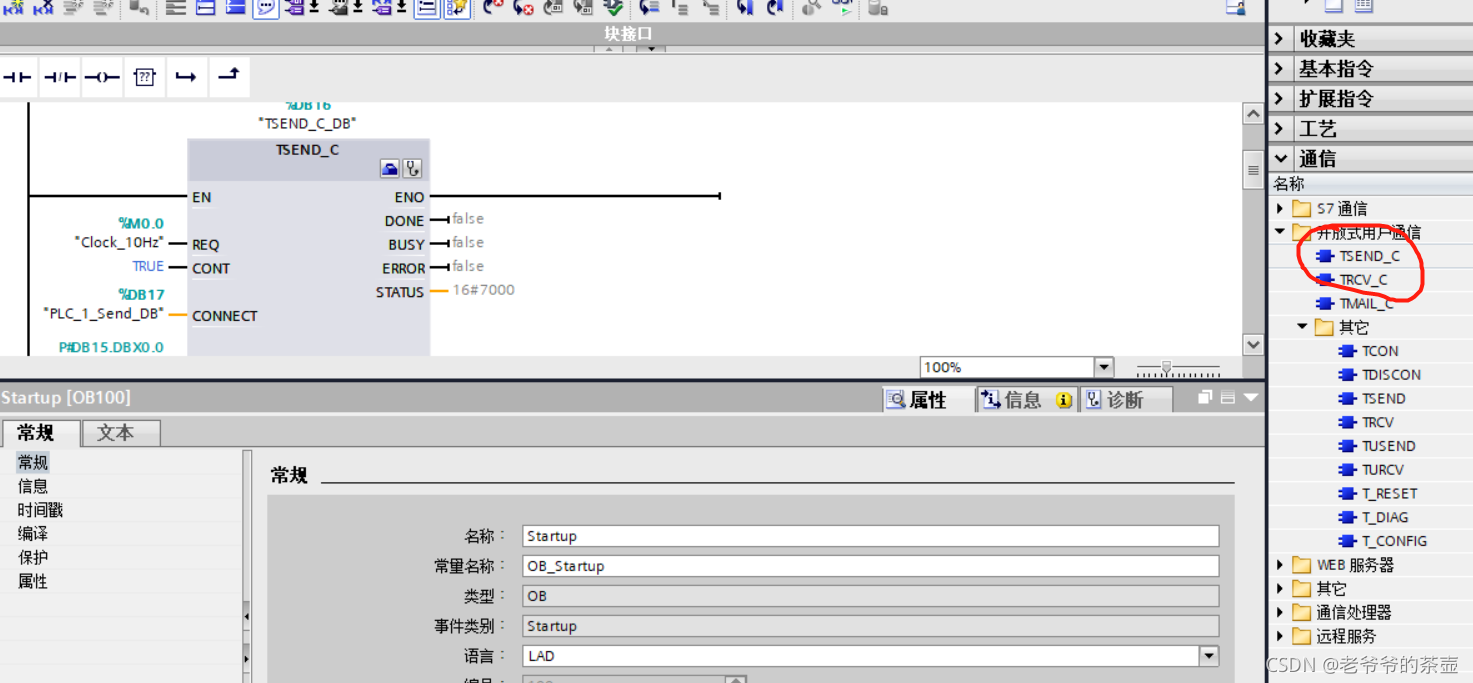
配好模块的IP地址,端口号,接收的缓存数据区,和要发送的数据
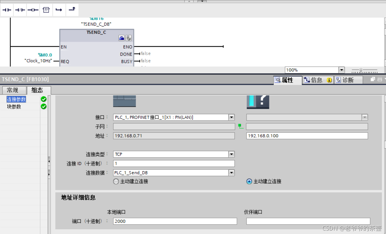
缓存的数据区域发送和接受都用同一个,系统会自动生成
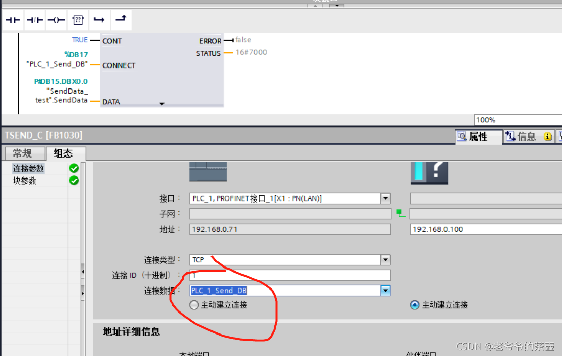
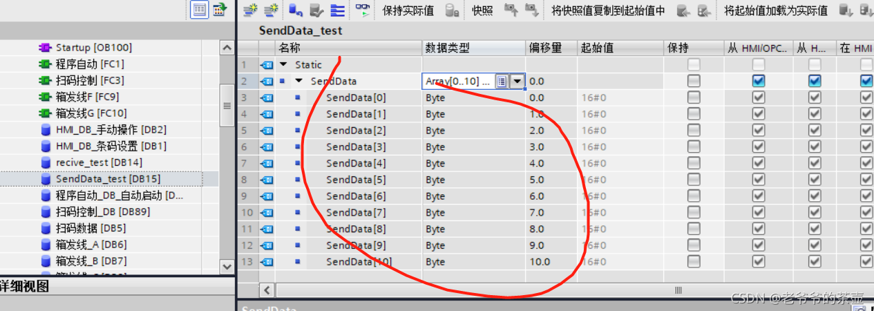
数据发送器我们自己建立:
我这里设置了11个byte的数组
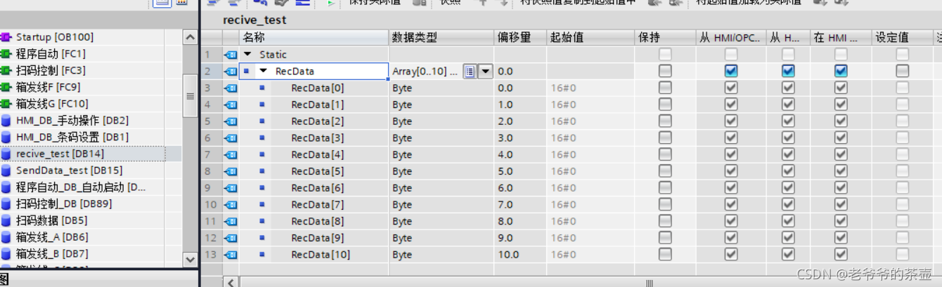
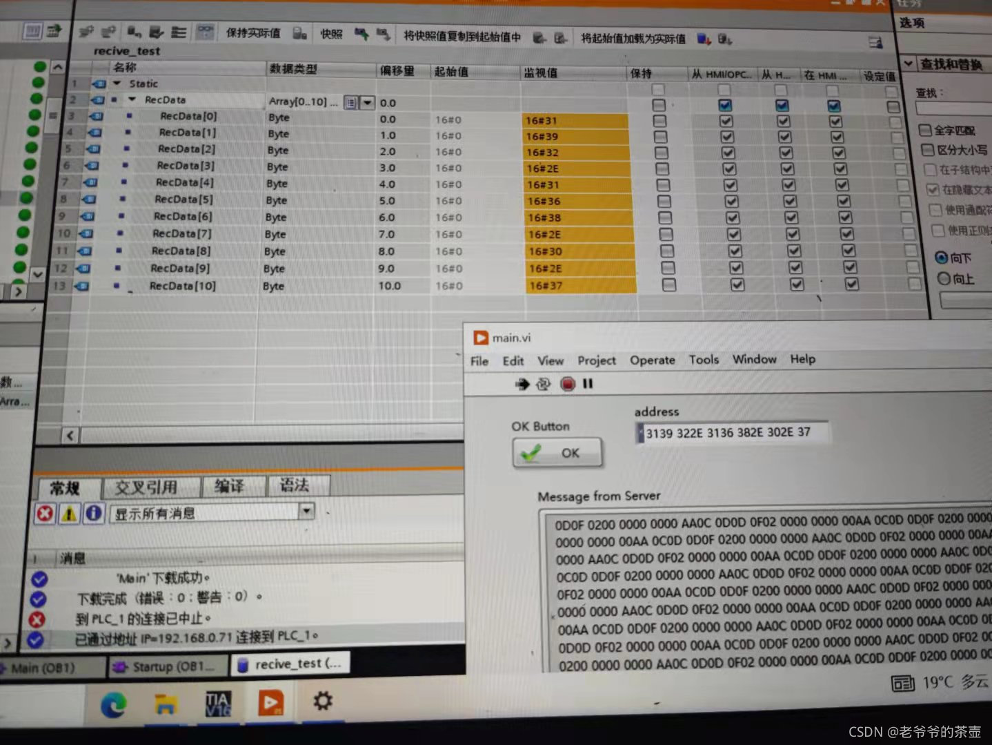
接收也配置了11个字节的数组
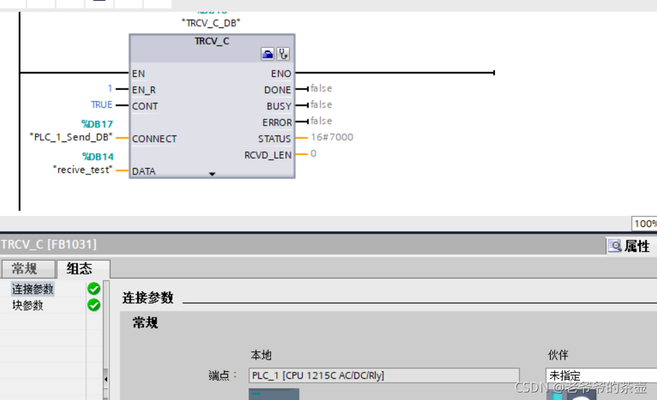
接收模块配置的参数如下
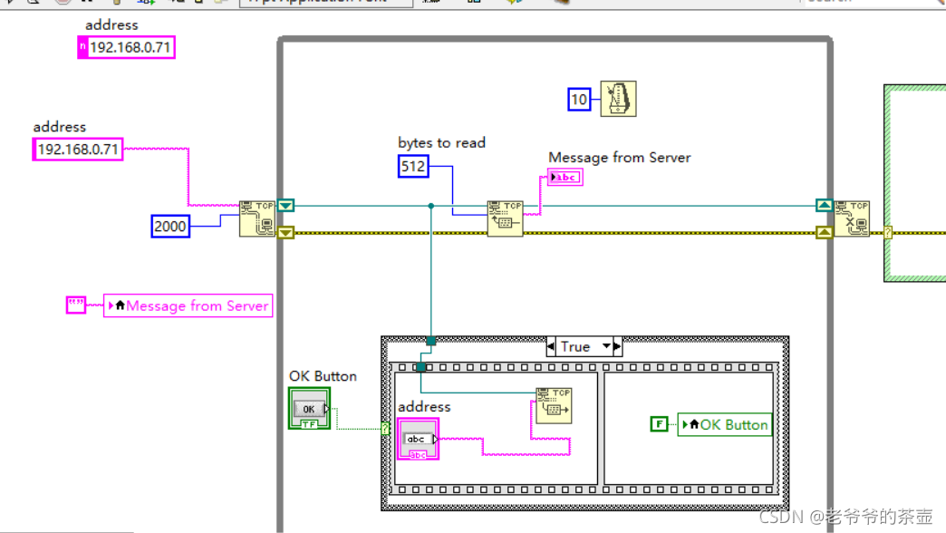
接下来我们通过Labview建立TCP连接
后面板
前面板:
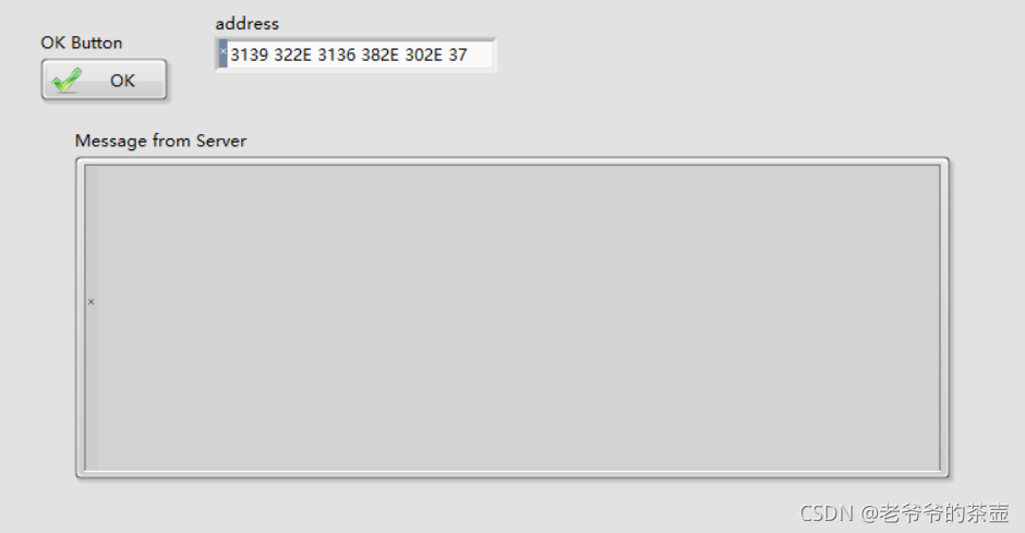
测试结果:发送的数据已经再windows端接收到
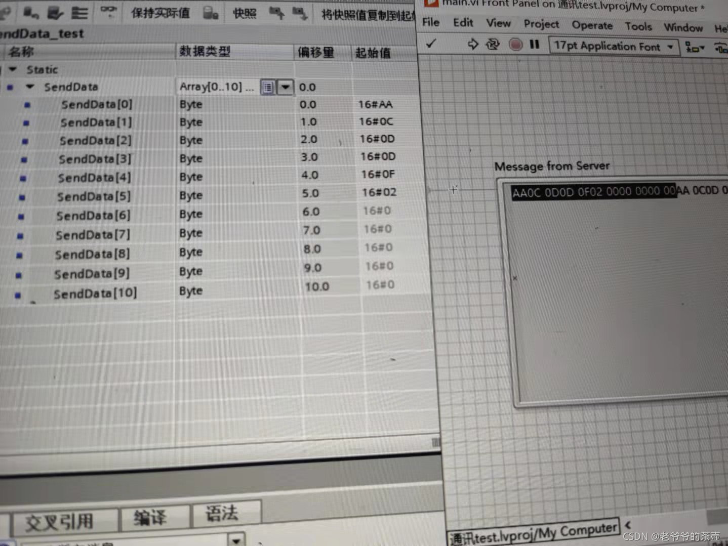
通过wondows发送的数据PLC也接收到了:
完成。
再PLC的接收端还有点小问题,不能一次全部接收到。
另外,下载IP地址和通讯IP地址不能是同一个,别人有冲突。


 1534
1534

 被折叠的 条评论
为什么被折叠?
被折叠的 条评论
为什么被折叠?
 到【灌水乐园】发言


