


小华HC32L136K8TA 单片机PRINTF
一、将前面建立好的工程文件LED_TEST文件夹复制一份,命名为PRINTF. 将LED_TEST\MDK\LED_TEST.uvprojx,改为PRINTF.uvprojx.双击这个文件打开工程。
二、修改工程配置
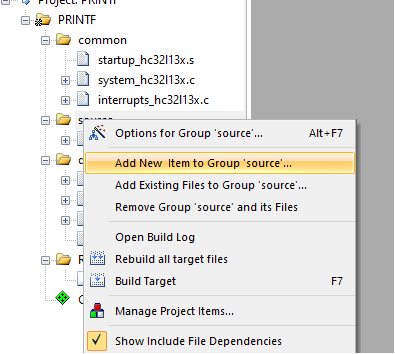
1.组driver下面添加uart.c
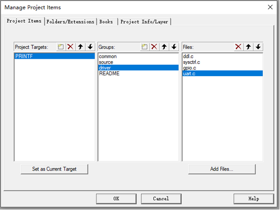
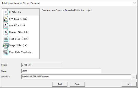
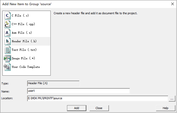
2.source下面添加usart.c,usart.h
usart.c的文件内容如下
#include "usart.h"
#include "gpio.h"
#include "uart.h"


//串口引脚配置
void UART0_PortInit(void)
{
  	stc_gpio_cfg_t stcGpioCfg;
    DDL_ZERO_STRUCT(stcGpioCfg);
    Sysctrl_SetPeripheralGate(SysctrlPeripheralGpio,TRUE); //使能GPIO模块时钟

    ///<TX
    stcGpioCfg.enDir = GpioDirOut;
#if defined(DEBUG_UART0_B6B7)
    Gpio_Init(GpioPortB, GpioPin6, &stcGpioCfg);
    Gpio_SetAfMode(GpioPortB, GpioPin6, GpioAf2);          //配置Pb6 端口为 010 ---- UART0_TXD UART0模块TXD信号
#elif defined(DEBUG_UART0_B8B9)
	Gpio_Init(GpioPortB, GpioPin8, &stcGpioCfg);
    Gpio_SetAfMode(GpioPortB, GpioPin8, GpioAf7);          //配置Pb8 端口为 ---- UART0_TXD UART0模块TXD信号
#elif defined(DEBUG_UART0_A9A10)
	Gpio_Init(GpioPortA, GpioPin9, &stcGpioCfg);
    Gpio_SetAfMode(GpioPortA, GpioPin9, GpioAf1);
#endif

    ///<RX
    stcGpioCfg.enDir = GpioDirIn;
#if defined(DEBUG_UART0_B6B7)
    Gpio_Init(GpioPortB, GpioPin7, &stcGpioCfg);
    Gpio_SetAfMode(GpioPortB, GpioPin7, GpioAf2);          //配置Pb7 端口010 ---- UART0_RXD UART0模块RXD信号
#elif defined(DEBUG_UART0_B8B9)
	Gpio_Init(GpioPortB, GpioPin9, &stcGpioCfg);
    Gpio_SetAfMode(GpioPortB, GpioPin9, GpioAf7);          //配置Pb9 端口 ---- UART0_RXD UART0模块RXD信号
#elif defined(DEBUG_UART0_A9A10)
	Gpio_Init(GpioPortA, GpioPin10, &stcGpioCfg);
    Gpio_SetAfMode(GpioPortA, GpioPin10, GpioAf1);
#endif

}


//串口配置
void Uart0Cfg(uint32_t baud)
{
    stc_uart_cfg_t    stcCfg;

    DDL_ZERO_STRUCT(stcCfg);

    ///< 开启外设时钟
    Sysctrl_SetPeripheralGate(SysctrlPeripheralUart0,TRUE);///<使能uart0模块时钟

    ///<UART Init
    stcCfg.enRunMode        = UartMskMode1;          ///<模式1
    stcCfg.enStopBit        = UartMsk1bit;           ///<1bit停止位
    //stcCfg.enMmdorCk        = UartMskEven;           ///<偶检验
	stcCfg.enMmdorCk        = UartMskDataOrAddr;//
    stcCfg.stcBaud.u32Baud  = baud;                  ///<波特率
    stcCfg.stcBaud.enClkDiv = UartMsk8Or16Div;       ///<通道采样分频配置 模式1/3 8分频
    stcCfg.stcBaud.u32Pclk  = Sysctrl_GetPClkFreq(); ///<获得外设时钟(PCLK)频率值
    Uart_Init(M0P_UART0, &stcCfg);                   ///<串口初始化

    ///<UART中断使能
    Uart_ClrStatus(M0P_UART0,UartRC);                ///<清接收请求
    Uart_ClrStatus(M0P_UART0,UartTC);                ///<清接收请求
    Uart_EnableIrq(M0P_UART0,UartRxIrq);             ///<使能串口接收中断
    //Uart_EnableIrq(M0P_UART0,UartTxIrq);             ///<使能串口发送中断
	Uart_DisableIrq(M0P_UART0,UartTxIrq);			//禁止发送中断
    EnableNvic(UART0_IRQn, IrqLevel3, TRUE);       ///<系统中断使能

}


Uart.h

//UART1中断
void Uart0_IRQHandler(void)
{
    uint8_t revdata;
	if(Uart_GetStatus(M0P_UART0, UartRC))
    {
        Uart_ClrStatus(M0P_UART0, UartRC);              //清除中断状态位
        revdata=Uart_ReceiveData(M0P_UART0);  //接收到数据
			  Uart_SendDataPoll(M0P_UART0,revdata);
         //Uart_DisableIrq(M0P_UART1,UartRxIrq);       //禁止接收中断
    }

    if(Uart_GetStatus(M0P_UART0, UartTC))
    {
        Uart_ClrStatus(M0P_UART0, UartTC);              //清除中断状态位
        //Uart_SendDataIt(M0P_UART0, 0x55);               //发送数据
		//Uart_DisableIrq(M0P_UART1,UartTxIrq);       //禁止发送中断
        //Uart_EnableIrq(M0P_UART1,UartRxIrq);        //使能接收中断
    }

}
usart.h
  #ifndef __USART_H
#define __USART_H

#include "ddl.h"

//#define DEBUG_UART0_B6B7          //测试成功
#define DEBUG_UART0_B8B9            //测试成功
//#define DEBUG_UART0_A9A10         //测试成功


void UART0_PortInit(void);
void Uart0Cfg(uint32_t baud);


#endif
Main.c
#include "gpio.h"
#include "usart.h"
static void App_LedInit(void);
int32_t main(void)
{
UART0_PortInit();
Uart0Cfg(57600);
printf("hello world \r\n");
while(1)
{
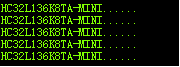
printf("HC32L136K8TA-MINI......\r\n");
delay1ms(1000);
}
}
Ddl.c修改
int fputc(int ch, FILE *f)
{
	Uart_SendDataPoll(M0P_UART0,ch);
    return ch;
}
编译下载,烧录后的打印效果


 5827
5827

 被折叠的 条评论
为什么被折叠?
被折叠的 条评论
为什么被折叠?
 到【灌水乐园】发言


