############################################################# # 1) Synthesis and Scripting Techniques for Designing Multi-Asynchronous Clock Designs #############################################################
1
Introduction
Multi-Clock design exits almost everywhere
2
Metastability
Dally and Poulton's Book 1) how metastability comes from 2) how metastability damage circuit generating unstable value propagating unstable value in combinational logic
3
Synchronizers
Dally and Poulton's Book MTBF Metastability theoretically cant be removed
4
Static Timing Analysis
1) What does STA do compared with Dynamic Verification 2) CDC path should not be analynized in STA
5
Clock Naming Convertions
identify clock source of signals by Naming Conventions 1) easy to read 2) easy to write synthesis script
6
Design Partitions
1) one clock in one module easy to do Synthesis and STA, such as group
2) one module for synchronizers from one clock to another
7
Synthesis Scripts & Timing Analysis
1) group modules of the same clock domain 2) set_false_path for CDC paths
8
Synchroning Fast Signals into Slow clock domain
Problem data loss Solution 1) pulse widen 2) handshake
9
Passing Multiple Control Signals (Take Caution)
Problem data coherence simplified design examples
Solutions 1)consolidate signals before passing them through clocks 2)generate new signals in new clock domain 3)and so on
10
Data-Path Synchronization
Solution 1) handshake A) valid(TX) ack(RX) B) ready(RX) valid(TX) ack(RX)
############################################################# # 2) Simulation and Synthesis Techniques for Asynchronous FIFO Design #############################################################
1
Introduction
2
Passing Multiple asynchronous signlas
1. be used to passing multiple asynchronous signals
2. major problem is to transfer pointers, usually with Gray code. however, binary pointer can also be used with handshake. these two methods will be compared.
3. FIFO correctness should be considerd from the start, it cant be garanteed by SDF simulation which relies on luck.
3
Gray code counter - Style #1
4
Gray code counter - Style #2
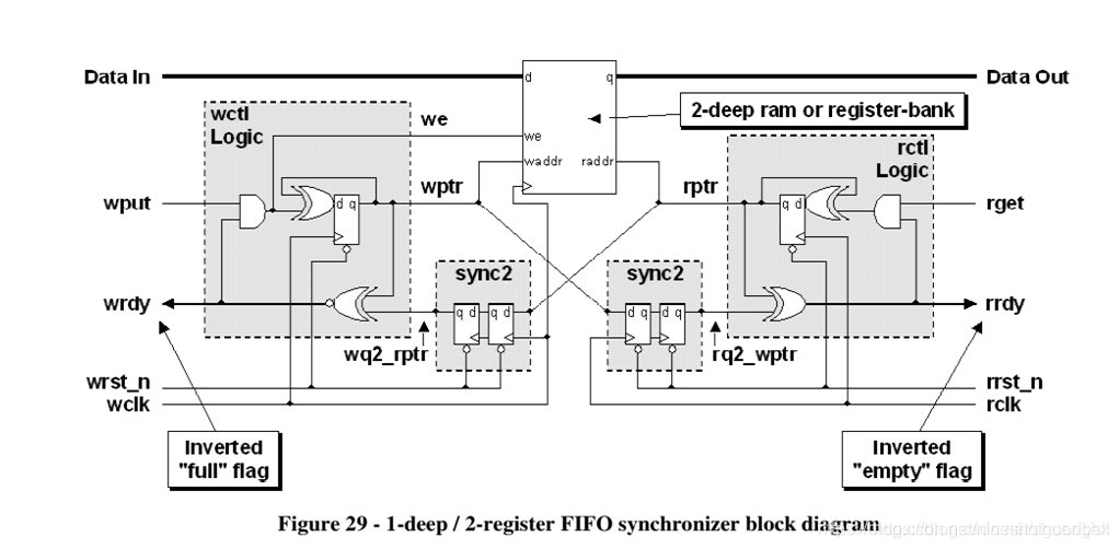
5
Handling full & empty conditions
1. full 2. empty 3. it works well even with different clock speed. two more questions are discussed. 4. pessimistic full & empty 5. it works well even with asynchronous reset
Two synchronization scenarios (1) It is permitted to miss samples that are passed between clock domains. (2) Every signal passed between clock domains must be sampled
MTBF 1) Two flip-flop synchronizer 2) Three flip-flop synchronizer, For some very high speed designs
Register signal in sending clock domain combinational logic will produce glitch that increase metastability chance or even worse sample intermediate state into destination clock domain
4
Synchronizing fast signals into slow clock domains
Solutions when missed samples are not allowed 1) An open-loop solution to ensure that signals are captured without acknowledgment 2) A closed-loop solution that requires acknowledgement of receipt of the signal that crosses a CDC boundary.
Requirement "Three edges" "1 to 1.25 or 1.5 clock period"
Comparison Open loop is fastest but not safe enough (difficult to maintain and modify) Close loop is safe but takes more delay in both clock domains
5
Passing multiple signals between clock domains
Problem skewed sampling of the multi-bit value
Solution 1) Multi-bit signal consolidation 2) Multi-cycle path formulations sending unsynchronized data to a receiving clock domain paired with a synchronized control signal i.e. handshake A) no feedback B) with feedback 3) Gray codes
1) Use a clock naming convention to identify the clock source of every signal in a design.
2) Partitioning Although tools have improved over the past decade to help automate the analysis and verification of signals in separate clock domains, it is still a good practice to approach multiclock design using good partitioning and naming conventions.
By partitioning a design to permit only one clock per module, static timing analysis becomes a significantly easier task for each domain in the design.
7
Multi-clock gate-level simulation issues
Problem X propagation
Solution set_annotate_check 0 -setup -hold
8
Summary & conclusions
1) Recommended 1-bit CDC techniques A) register the signal in the sending clock domain B) synchronize the signal into the receiving clock domain Multi-Cycle Path (MCP) formulation may be necessary.
2) Recommended multi-bit CDC techniques A) Consolidate B) Multi-Cycle Path (MCP) formulations C) FIFO D) gray code counters
3) Recommended naming conventions and design partitioning A) Use a clock-based naming convention B) As much as possible, partition the design sub-blocks into completely synchronous 1-clock designs


 被折叠的 条评论
为什么被折叠?
被折叠的 条评论
为什么被折叠?
 到【灌水乐园】发言


