


 本文详细介绍如何使用ros_arduino_bridge在ROS与Arduino间建立通信,包括安装配置、Arduino代码开发及ROS上位机开发等内容。
更多创客作品,请关注笔者网站园丁鸟,搜集全球极具创意,且有价值的创客作品
ros_arduino_bridge封装了通过串口于底盘控制器Arduino的通信,并提供了一个标准的base controller,所以对arduino资源的占用非常小,arduino只是作为一个单纯的硬件控制器来使用,而所有的运算逻辑都放在上位机进行,通过串口指令的方式控制Arduino程序的运行。在Arduino UNO编译一个完整的ros_arduino_bridge后的资源占用情况如下图:

从上图可以看出占用资源非常上,用户还可以在Arduino UNO开发更多的应用,接更多的传感器。
1.ros_arduino_bridge的安装
a.下载
进入你的workspace目录下的src目录,catkin_ws是workspace
cd ~/catkin_ws/src
git clone https://github.com/hbrobotics/ros_arduino_bridge.git
b.编译,在workspace目录编译
cd <catkin_ws>
catkin_make
c.拷贝Arduino看库文件到,相应的Arduino IDE的libraries目录
$ cd SKETCHBOOK_PATH//Arduino IDE的库文件目录
$ \cp -rp  `rospack find ros_arduino_firmware`/src/libraries/ROSArduinoBridge -T ROSArduinoBridge
这时候可以把ROSArduinoBridge拷贝到其他windows, Mac电脑的Arduino IDE环境下使用,重启后既可以用
2.开发Arduino 代码
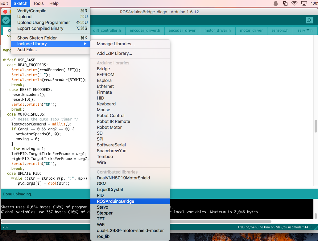
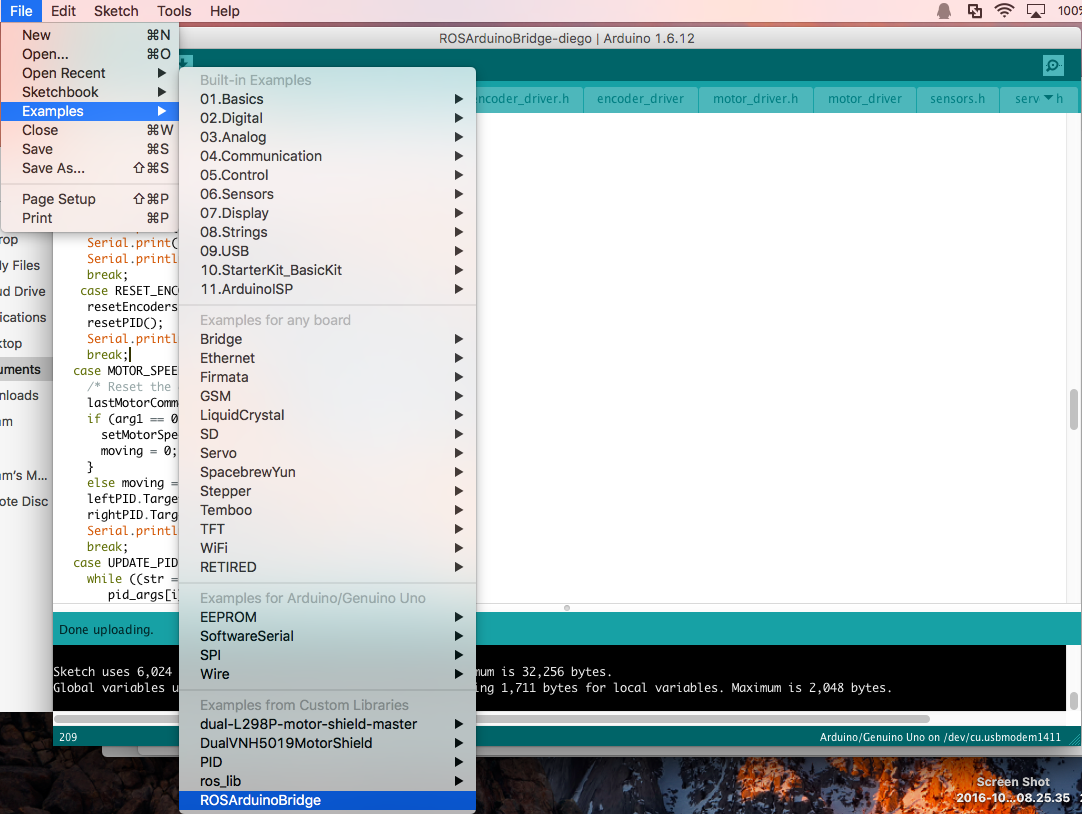
a.从Example中打开ROSArduinoBridge的示例代码,另存为自己喜欢的项目名称,我们只需要根据自己的需求修改示例代码即可
b.示例代码文件介绍
ROSArduinoBridge.ino 主程序
commands.h 串口命令的预定义
diff_controller.h PID控制代码
encoder_driver.h 编码器,这里只是针对了Arduino UNO,使用了中断接口D2,D3,和模拟接口A4,A5;所以电机编码器的输出接线需要按照此规则接线,另外要注意编码器要有两路输出
左侧电机的编码输出接D2,D3;右侧电机的编码输出接A4,A5
encoder_driver.ino 编码器的实现代码
motor_driver.h 马达驱动的接口定义,用不动的马达驱动板都要实现此文件定义的三个函数
motor_driver.ino马达驱动实现代码,根据预定义选择不同的驱动板库,在这里我使用了L298P,所以需要自己实现一个新的驱动库,后面会介绍
sensors.h传感器的实现文件
servos.h舵机的实现文件
c.为了满足我们控制的需要需要修改的是ROSArduinoBridge.ino文件,主要修改的点如下:
启用Base Controller
#define USE_BASE      // Enable the base controller code启用base controller
//#undef USE_BASE     // Disable the base controller code
马达控制板定义
/* Define the motor controller and encoder library you are using */
#ifdef USE_BASE
   /* The Pololu VNH5019 dual motor driver shield */
   //#define POLOLU_VNH5019

   /* The L298P dual motor driver shield,这里我们使用我们自己写的L298P库 */
   #define L298P


   /* The Pololu MC33926 dual motor driver shield */
   //#define POLOLU_MC33926

   /* The RoboGaia encoder shield */
   //#define ROBOGAIA

   /* Encoders directly attached to Arduino board,启用Arduino UNO的板载Encoder功能 */
   #define ARDUINO_ENC_COUNTER
#endif
定义电机PWM控制范围
/* Maximum PWM signal */
#define MAX_PWM        255//最大的PWM为255
d.motor_driver.ino的修改///主要是增加对L298P马达驱动板的支持
/***************************************************************
   Motor driver definitions

   Add a "#elif defined" block to this file to include support
   for a particular motor driver.  Then add the appropriate
   #define near the top of the main ROSArduinoBridge.ino file.

   *************************************************************/

#ifdef USE_BASE

#if defined POLOLU_VNH5019
  /* Include the Pololu library */
  #include "DualVNH5019MotorShield.h"

  /* Create the motor driver object */
  DualVNH5019MotorShield drive;

  /* Wrap the motor driver initialization */
  void initMotorController() {
    drive.init();
  }

  /* Wrap the drive motor set speed function */
  void setMotorSpeed(int i, int spd) {
    if (i == LEFT) drive.setM1Speed(spd);
    else drive.setM2Speed(spd);
  }

  // A convenience function for setting both motor speeds
  void setMotorSpeeds(int leftSpeed, int rightSpeed) {
    setMotorSpeed(LEFT, leftSpeed);
    setMotorSpeed(RIGHT, rightSpeed);
  }
#elif defined POLOLU_MC33926
  /* Include the Pololu library */
  #include "DualMC33926MotorShield.h"

  /* Create the motor driver object */
  DualMC33926MotorShield drive;

  /* Wrap the motor driver initialization */
  void initMotorController() {
    drive.init();
  }

  /* Wrap the drive motor set speed function */
  void setMotorSpeed(int i, int spd) {
    if (i == LEFT) drive.setM1Speed(spd);
    else drive.setM2Speed(spd);
  }

  // A convenience function for setting both motor speeds
  void setMotorSpeeds(int leftSpeed, int rightSpeed) {
    setMotorSpeed(LEFT, leftSpeed);
    setMotorSpeed(RIGHT, rightSpeed);
  }
#elif defined L298P////////增加对L298P的支持
   #include "DualL298PMotorShield.h"

  /* Create the motor driver object */
  DualL298PMotorShield drive;
  /* Wrap the motor driver initialization */
  void initMotorController() {
    drive.init();
  }

  /* Wrap the drive motor set speed function */
  void setMotorSpeed(int i, int spd) {
    if (i == LEFT) drive.setM1Speed(spd);
    else drive.setM2Speed(spd);
  }

  // A convenience function for setting both motor speeds
  void setMotorSpeeds(int leftSpeed, int rightSpeed) {
    setMotorSpeed(LEFT, leftSpeed);
    setMotorSpeed(RIGHT, rightSpeed);
  }

#else
  #error A motor driver must be selected!
#endif

#endif
e.L298P的驱动库,把.h和.cpp文件放在同一个目录下,拷贝到Arduino IDE的库文件目录下就可以。
DualL298PMotorShield.h代码
#ifndef DualL298PMotorShield_h
#define DualL298PMotorShield_h

#include <Arduino.h>

class DualL298PMotorShield
{
  public:
    // CONSTRUCTORS
    DualL298PMotorShield(); // Default pin selection.
    DualL298PMotorShield(unsigned char M1DIR, unsigned char M1PWM,
                           unsigned char M2DIR, unsigned char M2PWM); // User-defined pin selection.

    // PUBLIC METHODS
    void init(); // Initialize TIMER 1, set the PWM to 20kHZ.
    void setM1Speed(int speed); // Set speed for M1.
    void setM2Speed(int speed); // Set speed for M2.
    void setSpeeds(int m1Speed, int m2Speed); // Set speed for both M1 and M2.

  private:
    static const unsigned char _M1DIR = 4;
    static const unsigned char _M2DIR = 7;
    static const unsigned char _M1PWM = 5;
    static const unsigned char _M2PWM = 6;
};

#endif
DualL298PMotorShield.cpp代码
#include "DualL298PMotorShield.h"

// Constructors ////////////////////////////////////////////////////////////////

DualL298PMotorShield::DualL298PMotorShield()
{
  //Pin map

}


// Public Methods //////////////////////////////////////////////////////////////
void DualL298PMotorShield::init()
{
// Define pinMode for the pins and set the frequency for timer1.

  pinMode(_M1DIR,OUTPUT);
  pinMode(_M1PWM,OUTPUT);
  pinMode(_M2DIR,OUTPUT);
  pinMode(_M2PWM,OUTPUT);

}
// Set speed for motor 1, speed is a number betwenn -400 and 400
void DualL298PMotorShield::setM1Speed(int speed)
{
  unsigned char reverse = 0;

  if (speed < 0)
  {
    speed = -speed;  // Make speed a positive quantity
    reverse = 1;  // Preserve the direction
  }
  if (speed > 255)  // Max PWM dutycycle
    speed = 255;
  if (reverse)
  {
    digitalWrite(_M1DIR,LOW);
    analogWrite(_M1PWM, speed);
  }
  else
  {
    digitalWrite(_M1DIR,HIGH);
    analogWrite(_M1PWM, speed);
  }
}

// Set speed for motor 2, speed is a number betwenn -400 and 400
void DualL298PMotorShield::setM2Speed(int speed)
{
  unsigned char reverse = 0;

  if (speed < 0)
  {
    speed = -speed;  // Make speed a positive quantity
    reverse = 1;  // Preserve the direction
  }
  if (speed > 255)  // Max PWM dutycycle
    speed = 255;
  if (reverse)
  {
    digitalWrite(_M2DIR,LOW);
    analogWrite(_M2PWM, speed);
  }
  else
  {
    digitalWrite(_M2DIR,HIGH);
    analogWrite(_M2PWM, speed);
  }
}

// Set speed for motor 1 and 2
void DualL298PMotorShield::setSpeeds(int m1Speed, int m2Speed)
{
  setM1Speed(m1Speed);
  setM2Speed(m2Speed);
}
修改完成后变可以编译upload到Arduino UNO上了。
3.ROS上位机开发
a.配置你的机器人参数
进入配置文件目录
$ roscd ros_arduino_python/config
拷贝一份新的配置文件
$ cp arduino_params.yaml my_arduino_params.yaml
用nano打开编辑
sudo nano my_arduino_params.yaml
修改后的my_arduino_params.yaml如下图,主要修改就是启用base Controller,修改PID参数,修改机器人的参数:
# For a direct USB cable connection, the port name is typically
# /dev/ttyACM# where is # is a number such as 0, 1, 2, etc
# For a wireless connection like XBee, the port is typically
# /dev/ttyUSB# where # is a number such as 0, 1, 2, etc.

port: /dev/ttyACM0
baud: 57600
timeout: 0.1

rate: 50
sensorstate_rate: 10

use_base_controller: True
base_controller_rate: 10

# For a robot that uses base_footprint, change base_frame to base_footprint
base_frame: base_link

# === Robot drivetrain parameters
wheel_diameter: 0.02900 #轮胎直径
wheel_track: 0.18 #两个轮胎间距
encoder_resolution: 2 # 码盘孔数
gear_reduction: 75.0 #转速比
motors_reversed: True

# === PID parameters
Kp: 10
Kd: 12
Ki: 0
Ko: 50
accel_limit: 1.0

# === Sensor definitions.  Examples only - edit for your robot.
#     Sensor type can be one of the follow (case sensitive!):
#	  * Ping
#	  * GP2D12
#	  * Analog
#	  * Digital
#	  * PololuMotorCurrent
#	  * PhidgetsVoltage
#	  * PhidgetsCurrent (20 Amp, DC)


sensors: {
  #motor_current_left:   {pin: 4, type: PololuMotorCurrent, rate: 5},
  #motor_current_right:  {pin: 7, type: PololuMotorCurrent, rate: 5},
  #ir_front_center:      {pin: 2, type: GP2D12, rate: 10},
  #sonar_front_center:   {pin: 5, type: Ping, rate: 10},
  arduino_led:          {pin: 13, type: Digital, rate: 5, direction: output}
}
修改完成后,既可以运行了
b.运行测试
启动roscore
roscore
增加路径到bash
. ~/catkin_ws/devel/setup.bash
启动节点
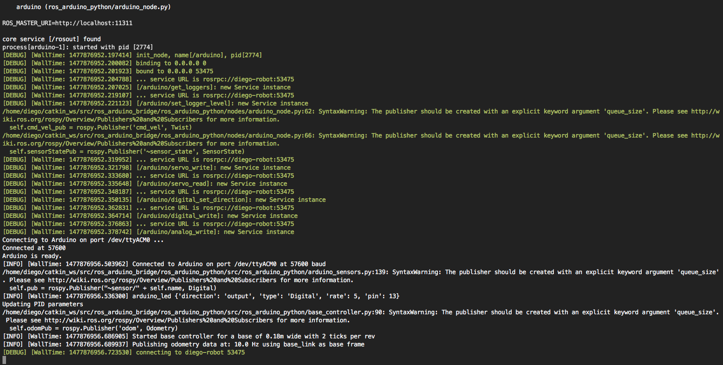
roslaunch ros_arduino_python arduino.launch
启动后的截图
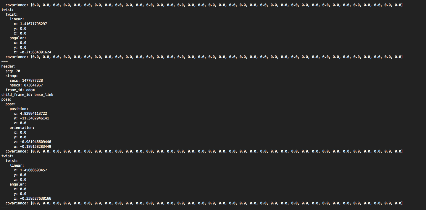
这时候我们可以发布Twist消息来控制机器人的运行,如:
rostopic pub /cmd_vel geometry_msgs/Twist -r 1 -- '[2.0, 0.0, 0.0]' '[0.0, 0.0, 1.8]'
运行此命令,机器人会原地打转,用如下命令查看odom的信息,此信息会不断的变化
rostopic echo /odom
```
至此机器人已经可以按照Twist消息进行控制,发布功move base使用的odom信息,不过做到这里,为了控制精度,我们还需要标定机器人,即标定机器人按照机器人给定的线速度,和角速度行进,下篇博文,我们将讲述如何标定。


 1万+
1万+

 被折叠的 条评论
为什么被折叠?
被折叠的 条评论
为什么被折叠?
 到【灌水乐园】发言


