


关于FastLED库添加LED SM16705PD芯片过程
关于FastLED库添加未知LED芯片过程
注意:这只是本人随便做的记录,仅供参考
环境: vscode + PlatformIO
芯片:
测试: ws2812b
修改后的测试: SM16705PD
其他芯片添加可以参考一下!
一、导入FastLED库
1. 搜索FastLED库
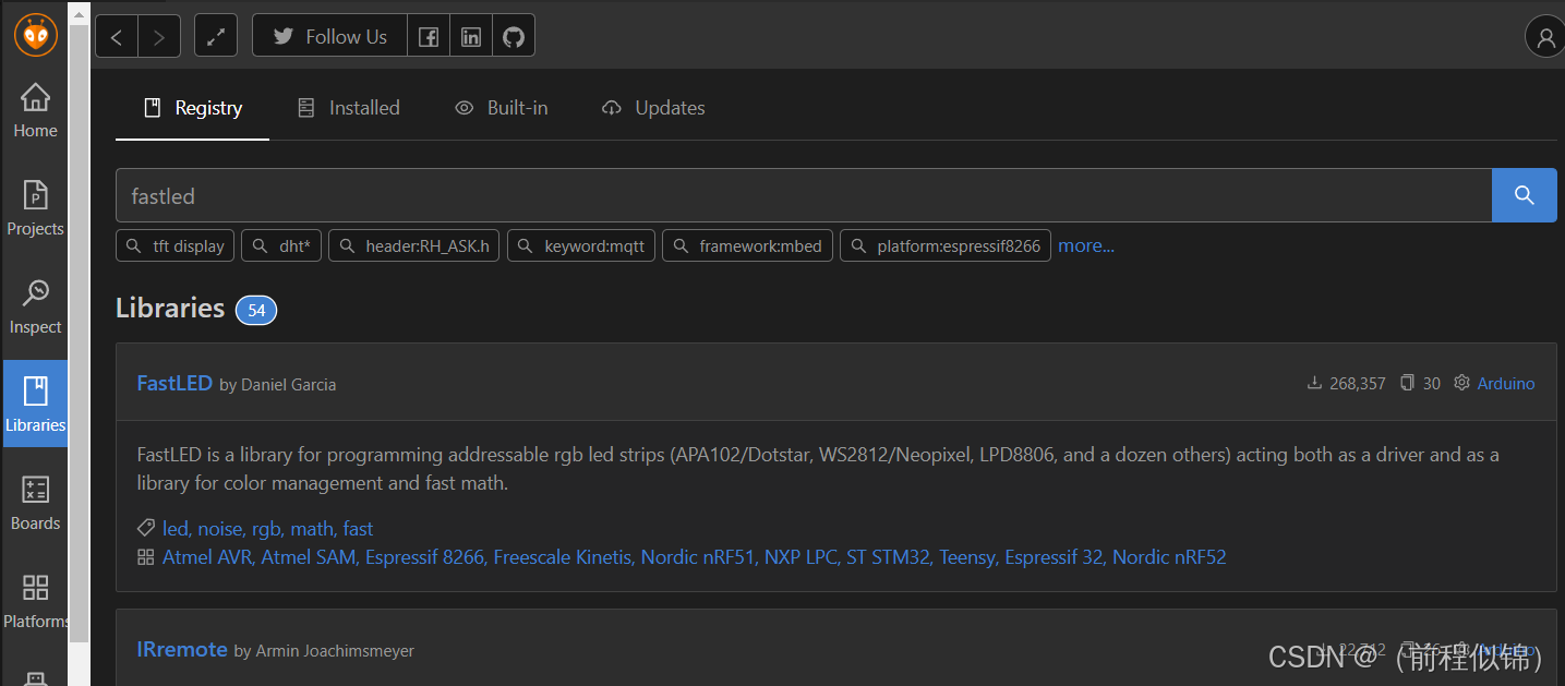
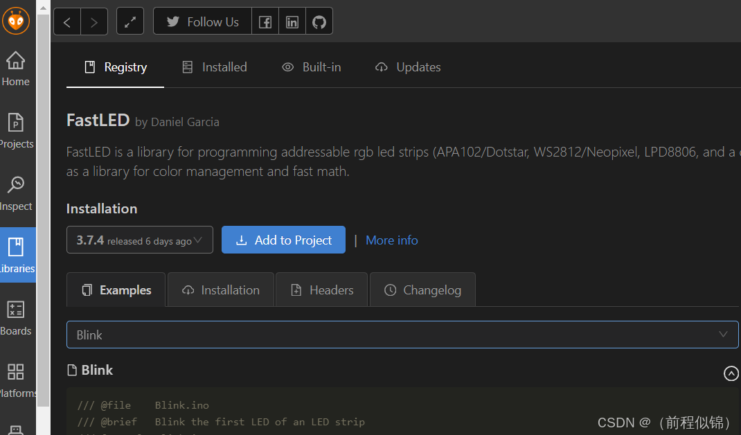
2. 选择版本
- 我选择的是目前最新版本 3.7.4
- 选择后点击添加到项目即可
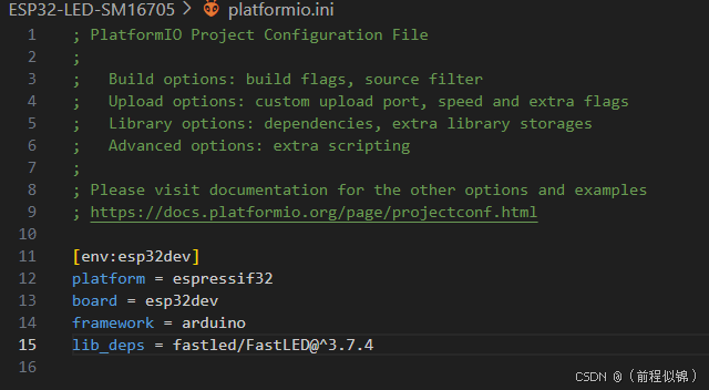
3. 导入项目
- 在项目文件里面就可以看见导入的库了
二、写个 LED 例程
- 随便写个可以运行LED灯带的项目(一般ws2812b最为经典,也最为常用)
#include "FastLED.h"

// 定义LED的数量和连接的引脚
#define NUM_LEDS 12  //12颗灯
#define DATA_PIN 12  //引脚
// 定义LED的类型。这里以常见的WS2812B为例
CRGB leds[NUM_LEDS];
void setup() {
  // 初始化串口通讯
  Serial.begin(115200);
  // 初始化FastLED,设置引脚和数据速率
  FastLED.addLeds<WS2812, DATA_PIN, RGB>(leds, NUM_LEDS).setCorrection(TypicalLEDStrip);
  // 设置亮度,范围为0(关闭)到255(最亮)
  FastLED.setBrightness(50);
}
void loop() {
  // 遍历所有LED,并将它们逐个设置为红色
  for(int i = 0; i < NUM_LEDS; i++) {
    leds[i] = CRGB::Yellow;
    // 发送数据到LED条,更新显示
    FastLED.show();
    // 等待一小段时间后点亮下一个LED
    delay(500);
  }
  // 等待一小段时间后再次更新
  delay(1000);
  // 遍历所有LED,并将它们逐个设置为蓝色
  for(int i = 0; i < NUM_LEDS; i++) {
    leds[i] = CRGB::Green;
    // 发送数据到LED条,更新显示
    FastLED.show();
    // 等待一小段时间后点亮下一个LED
    delay(500);
  }
  // 等待一小段时间后再次更新
  delay(1000);
}
- 复制文件到项目运行测试这个代码是否可用(可用就进行下一步)
三、定位修改文件位置
1. 需要在 FastLED.h 文件内添加芯片模板
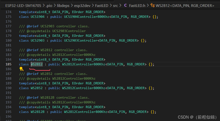
(1) 找到 WS2812 这个变量 的位置
(2) 按 Ctrl + 右键 进入WS2812所在位置 FastLED.h 文件
(3)
(4)
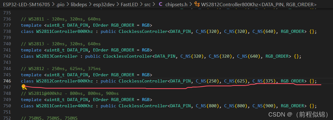
2. 在 chipsets.h 文件添加一个模板
(1) 在这之前还需要去实现我们需要的 SM16705PD芯片的父类
(2) 所以先进入WS2812的父类
(3) 按 Ctrl + 右键 点击 父类 WS2812Controller800Khz 进入父类所在文件 chipsets.h
3. 在 clockless_rmt_esp32.h 文件修改(对类进行派生扩展)
(1) 按 Ctrl + 右键 进入 ClocklessController所在位置 clockless_rmt_esp32.h
(2) 准备对文件进行修改派生
4. 在 controller.h 添加 loadAndScale 和 getScale 的实例化对象
(1) 在文件里面有个叫 pixels.loadAndScale0() 的代码
(2) 按 Ctrl + 右键 进入找到其位置,总的有 3 个派生函数都需要添加(这里原本只有3个,被我改为了9个)
5. 在 pixeltypes.h 文件下 EOrder 枚举里面添加 颜色通道
(1) 在 main.cpp文件里面找到 RGB 这个变量, 按 Ctrl + 右键 进入枚举 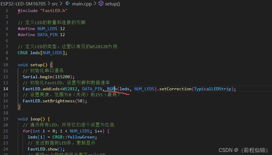
(2) 添加枚举类型画圈部分都是(这里面 0 :红色 ,1:绿色,2:蓝色,3:白色,4:黄色)
6. 在 controller.h 里面修改 下面这几段代码
#define RGB_BYTE(RO,X) (((RO)>>(3*(2-(X)))) & 0x3)

/// @see RGB_BYTE(RO,X)
#define RGB_BYTE0(RO) ((RO>>6) & 0x3)
/// Gets the color channel for byte 1.
/// @see RGB_BYTE(RO,X)
#define RGB_BYTE1(RO) ((RO>>3) & 0x3)
/// Gets the color channel for byte 2.
/// @see RGB_BYTE(RO,X)
#define RGB_BYTE2(RO) ((RO) & 0x3)
四、修改文件
注意:文件修改顺序可能要变,不按寻找顺序来。
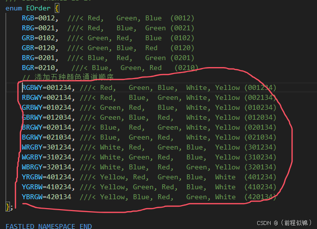
1. 首先在 EOrder 枚举里面添加 颜色通道(在RGB 后面添加即可)
// 添加五种颜色通道顺序
    RGBWY=001234, ///< Red,   Green, Blue,  White, Yellow (001234)
    RBGWY=002134, ///< Red,   Blue,  Green, White, Yellow (002134)
    GRBWY=010234, ///< Green, Red,   Blue,  White, Yellow (010234)
    GBRWY=012034, ///< Green, Blue,  Red,   White, Yellow (012034)
    BRGWY=020134, ///< Blue,  Red,   Green, White, Yellow (020134)
    BGRWY=021034, ///< Blue,  Green, Red,   White, Yellow (021034)
    WRGBY=301234, ///< White, Red,   Green, Blue,  Yellow (301234)
    WGRBY=310234, ///< White, Green, Red,   Blue,  Yellow (310234)
    WBRGY=320134, ///< White, Blue,  Red,   Green, Yellow (320134)
    YRGBW=401234, ///< Yellow, Red,  Green, Blue,  White  (401234)
    YGRBW=410234, ///< Yellow, Green, Red,  Blue,  White  (410234)
    YBRGW=420134  ///< Yellow, Blue, Red,   Green, White  (420134)
2. 修改 controller.h 里面 的 RGB_BYTE 计算值(不修改无法使用4和5通道,那么前面 EOrder 里面我们自己定义的值就没有用)
#define RO(X) RGB_BYTE(RGB_ORDER, X)

/// Gets the assigned color channel for a byte's position in the output,
/// using a passed RGB color order
/// @param RO the RGB color order
/// @param X the byte's position in the output (0-2)
/// @returns the color channel for that byte (0 = red, 1 = green, 2 = blue)
/// @see EOrder
// #define RGB_BYTE(RO,X) (((RO)>>(3*(2-(X)))) & 0x3) //原来的值
#define RGB_BYTE(RO,X) (((RO)>>(3*(4-(X)))) & 0x7)
// Gets the color channel for byte 0.
// /// @see RGB_BYTE(RO,X)
// #define RGB_BYTE0(RO) ((RO>>6) & 0x3) //原来的值
// /// Gets the color channel for byte 1.
// /// @see RGB_BYTE(RO,X)
// #define RGB_BYTE1(RO) ((RO>>3) & 0x3) //原来的值
// /// Gets the color channel for byte 2.
// /// @see RGB_BYTE(RO,X)
// #define RGB_BYTE2(RO) ((RO) & 0x3) //原来的值

/// 获取字节 0 的颜色通道。
/// @see RGB_BYTE(RO,X)
#define RGB_BYTE0(RO) ((RO>>12) & 0x7)
/// 获取字节 1 的颜色通道。
/// @see RGB_BYTE(RO,X)
#define RGB_BYTE1(RO) ((RO>>9) & 0x7)
/// 获取字节 2 的颜色通道。
/// @see RGB_BYTE(RO,X)
#define RGB_BYTE2(RO) ((RO>>6) & 0x7)
/// 获取字节 3 的颜色通道。
/// @see RGB_BYTE(RO,X)
#define RGB_BYTE3(RO) ((RO>>3) & 0x7)
/// 获取字节 4 的颜色通道。
/// @see RGB_BYTE(RO,X)
#define RGB_BYTE4(RO) ((RO) & 0x7)
3. 在 clockless_rmt_esp32.h 文件修改(对类进行派生扩展)
- 直接写个基类,并派生出两个类 ClocklessController80Bit 和 ClocklessController
- 值得注意的是 ClocklessController 就是本来库的类,只是我们对其稍微修改了下,让其成为其中一个派生类。
// 基类,包含虚函数
template <int DATA_PIN, int T1, int T2, int T3, EOrder RGB_ORDER = RGB, int XTRA0 = 0, bool FLIP = false, int WAIT_TIME = 5>
class ClocklessControllerBase : public CPixelLEDController<RGB_ORDER>{}

// 处理80位数据的派生类
template <int DATA_PIN, int T1, int T2, int T3, EOrder RGB_ORDER = RGB, int XTRA0 = 0, bool FLIP = false, int WAIT_TIME = 5>
class ClocklessController80Bit : public ClocklessControllerBase<DATA_PIN, T1, T2, T3, RGB_ORDER, XTRA0, FLIP, WAIT_TIME>{}

// 处理24位数据的派生类
template <int DATA_PIN, int T1, int T2, int T3, EOrder RGB_ORDER = RGB, int XTRA0 = 0, bool FLIP = false, int WAIT_TIME = 5>
class ClocklessController : public ClocklessControllerBase<DATA_PIN, T1, T2, T3, RGB_ORDER, XTRA0, FLIP, WAIT_TIME>{}
#pragma once
#include "rmt.h"
FASTLED_NAMESPACE_BEGIN
#define FASTLED_HAS_CLOCKLESS 1
#define NUM_COLOR_CHANNELS 3

// 基类,包含虚函数
template <int DATA_PIN, int T1, int T2, int T3, EOrder RGB_ORDER = RGB, int XTRA0 = 0, bool FLIP = false, int WAIT_TIME = 5>
class ClocklessControllerBase : public CPixelLEDController<RGB_ORDER>
{
protected:
    ESP32RMTController mRMTController;
    static_assert(FastPin<DATA_PIN>::validpin(), "Invalid pin specified");
public:
    ClocklessControllerBase()
        : mRMTController(DATA_PIN, T1, T2, T3, FASTLED_RMT_MAX_CHANNELS, FASTLED_RMT_BUILTIN_DRIVER)
    {}
    virtual void init() {}
    virtual uint16_t getMaxRefreshRate() const { return 400; }
    // 虚函数,派生类需要实现
    virtual void loadPixelData(PixelController<RGB_ORDER> & pixels) = 0;
    virtual void showPixels(PixelController<RGB_ORDER> & pixels) = 0;
};
// 处理80位数据的派生类
template <int DATA_PIN, int T1, int T2, int T3, EOrder RGB_ORDER = RGB, int XTRA0 = 0, bool FLIP = false, int WAIT_TIME = 5>
class ClocklessController80Bit : public ClocklessControllerBase<DATA_PIN, T1, T2, T3, RGB_ORDER, XTRA0, FLIP, WAIT_TIME>
{
public:
    using ClocklessControllerBase<DATA_PIN, T1, T2, T3, RGB_ORDER, XTRA0, FLIP, WAIT_TIME>::ClocklessControllerBase;

    void loadPixelData(PixelController<RGB_ORDER> & pixels) override
    {
        int size_in_bytes = pixels.size() * 10; // 5个颜色通道,每个16位
        uint8_t * pData = this->mRMTController.getPixelBuffer(size_in_bytes);

        while (pixels.has(1)) {
            // *pData++ = pixels.loadAndScale0();
            // *pData++ = pixels.loadAndScale1();
            // *pData++ = pixels.loadAndScale2();
            // *pData++ = pixels.loadAndScale3();
            // *pData++ = pixels.loadAndScale4();
            // *pData++ = pixels.loadAndScale5();
            // *pData++ = pixels.loadAndScale6();
            // *pData++ = pixels.loadAndScale7();
            // *pData++ = pixels.loadAndScale8();
            // *pData++ = pixels.loadAndScale9();
            uint8_t r = pixels.loadAndScale0();
            uint8_t g = pixels.loadAndScale1();
            uint8_t b = pixels.loadAndScale2();
            uint8_t w = 0;
            uint8_t y = 0;


            // *pData++ = r >> 8;
            // *pData++ = r & 0xFF;
            // *pData++ = g >> 8;
            // *pData++ = g & 0xFF;
            // *pData++ = b >> 8;
            // *pData++ = b & 0xFF;
            // *pData++ = w >> 8;
            // *pData++ = w & 0xFF;
            // *pData++ = y >> 8;
            // *pData++ = y & 0xFF;
            // 将8位颜色数据扩展为16位
            *pData++ = r; // 高8位
            *pData++ = r; // 低8位
            *pData++ = g; // 高8位
            *pData++ = g; // 低8位
            *pData++ = b; // 高8位
            *pData++ = b; // 低8位
            *pData++ = w; // 高8位
            *pData++ = w; // 低8位
            *pData++ = y; // 高8位
            *pData++ = y; // 低8位

            pixels.advanceData();
            pixels.stepDithering();
        }
    }
    void showPixels(PixelController<RGB_ORDER> & pixels) override
    {
        this->loadPixelData(pixels);
        this->mRMTController.showPixels();
        // this->sendStandbyCommand(); // 发送待机指令
    }
    void sendStandbyCommand() {
        // 待机指令数据为 2'b01
        uint8_t standbyData = 0b01;
        sendData(standbyData);
    }
private:
    void sendData(uint8_t data) {
        uint8_t * pData = this->mRMTController.getPixelBuffer(1);
        *pData = data;
        this->mRMTController.showPixels();
    }
};
// 处理24位数据的派生类
template <int DATA_PIN, int T1, int T2, int T3, EOrder RGB_ORDER = RGB, int XTRA0 = 0, bool FLIP = false, int WAIT_TIME = 5>
class ClocklessController : public ClocklessControllerBase<DATA_PIN, T1, T2, T3, RGB_ORDER, XTRA0, FLIP, WAIT_TIME>
{
public:
    using ClocklessControllerBase<DATA_PIN, T1, T2, T3, RGB_ORDER, XTRA0, FLIP, WAIT_TIME>::ClocklessControllerBase;

    void loadPixelData(PixelController<RGB_ORDER> & pixels) override
    {
        int size_in_bytes = pixels.size() * 3; // 3个颜色通道,每个8位
        uint8_t * pData = this->mRMTController.getPixelBuffer(size_in_bytes);

        while (pixels.has(1)) {
            *pData++ = pixels.loadAndScale0();
            *pData++ = pixels.loadAndScale1();
            *pData++ = pixels.loadAndScale2();
            pixels.advanceData();
        }
    }
    void showPixels(PixelController<RGB_ORDER> & pixels) override
    {
        this->loadPixelData(pixels);
        this->mRMTController.showPixels();
    }
};
FASTLED_NAMESPACE_END
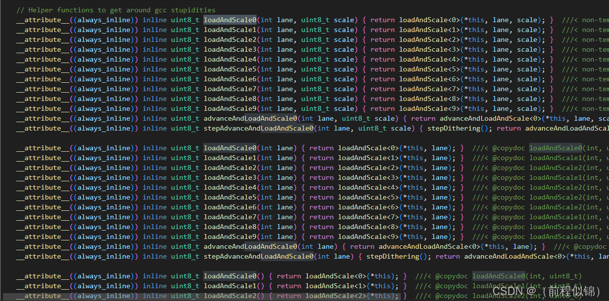
4. 在 controller.h 添加 loadAndScale 和 getScale 的实例化对象
(1) 在文件里面有个叫 pixels.loadAndScale0() 的代码
(2) 按 Ctrl + 右键 进入找到其位置,总的有 3 个派生函数都需要添加(这里原本只有3个,被我改为了9个)
// Helper functions to get around gcc stupidities
        __attribute__((always_inline)) inline uint8_t loadAndScale0(int lane, uint8_t scale) { return loadAndScale<0>(*this, lane, scale); }  ///< non-template alias of loadAndScale<0>()
        __attribute__((always_inline)) inline uint8_t loadAndScale1(int lane, uint8_t scale) { return loadAndScale<1>(*this, lane, scale); }  ///< non-template alias of loadAndScale<1>()
        __attribute__((always_inline)) inline uint8_t loadAndScale2(int lane, uint8_t scale) { return loadAndScale<2>(*this, lane, scale); }  ///< non-template alias of loadAndScale<2>()
        __attribute__((always_inline)) inline uint8_t loadAndScale3(int lane, uint8_t scale) { return loadAndScale<3>(*this, lane, scale); }  ///< non-template alias of loadAndScale<3>()//自己添加的
        __attribute__((always_inline)) inline uint8_t loadAndScale4(int lane, uint8_t scale) { return loadAndScale<4>(*this, lane, scale); }  ///< non-template alias of loadAndScale<4>()//自己添加的
        __attribute__((always_inline)) inline uint8_t loadAndScale5(int lane, uint8_t scale) { return loadAndScale<5>(*this, lane, scale); }  ///< non-template alias of loadAndScale<4>()//自己添加的
        __attribute__((always_inline)) inline uint8_t loadAndScale6(int lane, uint8_t scale) { return loadAndScale<6>(*this, lane, scale); }  ///< non-template alias of loadAndScale<2>()
        __attribute__((always_inline)) inline uint8_t loadAndScale7(int lane, uint8_t scale) { return loadAndScale<7>(*this, lane, scale); }  ///< non-template alias of loadAndScale<3>()//自己添加的
        __attribute__((always_inline)) inline uint8_t loadAndScale8(int lane, uint8_t scale) { return loadAndScale<8>(*this, lane, scale); }  ///< non-template alias of loadAndScale<4>()//自己添加的
        __attribute__((always_inline)) inline uint8_t loadAndScale9(int lane, uint8_t scale) { return loadAndScale<9>(*this, lane, scale); }  ///< non-template alias of loadAndScale<4>()//自己添加的
        __attribute__((always_inline)) inline uint8_t advanceAndLoadAndScale0(int lane, uint8_t scale) { return advanceAndLoadAndScale<0>(*this, lane, scale); }  ///< non-template alias of advanceAndLoadAndScale<0>()
        __attribute__((always_inline)) inline uint8_t stepAdvanceAndLoadAndScale0(int lane, uint8_t scale) { stepDithering(); return advanceAndLoadAndScale<0>(*this, lane, scale); }  ///< stepDithering() and advanceAndLoadAndScale0()

        __attribute__((always_inline)) inline uint8_t loadAndScale0(int lane) { return loadAndScale<0>(*this, lane); }  ///< @copydoc loadAndScale0(int, uint8_t)
        __attribute__((always_inline)) inline uint8_t loadAndScale1(int lane) { return loadAndScale<1>(*this, lane); }  ///< @copydoc loadAndScale1(int, uint8_t)
        __attribute__((always_inline)) inline uint8_t loadAndScale2(int lane) { return loadAndScale<2>(*this, lane); }  ///< @copydoc loadAndScale2(int, uint8_t)
        __attribute__((always_inline)) inline uint8_t loadAndScale3(int lane) { return loadAndScale<3>(*this, lane); }  ///< @copydoc loadAndScale1(int, uint8_t)//自己添加的
        __attribute__((always_inline)) inline uint8_t loadAndScale4(int lane) { return loadAndScale<4>(*this, lane); }  ///< @copydoc loadAndScale2(int, uint8_t)//自己添加的
        __attribute__((always_inline)) inline uint8_t loadAndScale5(int lane) { return loadAndScale<5>(*this, lane); }  ///< @copydoc loadAndScale2(int, uint8_t)//自己添加的
        __attribute__((always_inline)) inline uint8_t loadAndScale6(int lane) { return loadAndScale<6>(*this, lane); }  ///< @copydoc loadAndScale2(int, uint8_t)
        __attribute__((always_inline)) inline uint8_t loadAndScale7(int lane) { return loadAndScale<7>(*this, lane); }  ///< @copydoc loadAndScale1(int, uint8_t)//自己添加的
        __attribute__((always_inline)) inline uint8_t loadAndScale8(int lane) { return loadAndScale<8>(*this, lane); }  ///< @copydoc loadAndScale2(int, uint8_t)//自己添加的
        __attribute__((always_inline)) inline uint8_t loadAndScale9(int lane) { return loadAndScale<9>(*this, lane); }  ///< @copydoc loadAndScale2(int, uint8_t)//自己添加的
        __attribute__((always_inline)) inline uint8_t advanceAndLoadAndScale0(int lane) { return advanceAndLoadAndScale<0>(*this, lane); }  ///< @copydoc advanceAndLoadAndScale0(int, uint8_t)
        __attribute__((always_inline)) inline uint8_t stepAdvanceAndLoadAndScale0(int lane) { stepDithering(); return advanceAndLoadAndScale<0>(*this, lane); }  ///< @copydoc stepAdvanceAndLoadAndScale0(int, uint8_t)

        __attribute__((always_inline)) inline uint8_t loadAndScale0() { return loadAndScale<0>(*this); }  ///< @copydoc loadAndScale0(int, uint8_t)
        __attribute__((always_inline)) inline uint8_t loadAndScale1() { return loadAndScale<1>(*this); }  ///< @copydoc loadAndScale1(int, uint8_t)
        __attribute__((always_inline)) inline uint8_t loadAndScale2() { return loadAndScale<2>(*this); }  ///< @copydoc loadAndScale2(int, uint8_t)
        __attribute__((always_inline)) inline uint8_t loadAndScale3() { return loadAndScale<3>(*this); }  ///< @copydoc loadAndScale1(int, uint8_t)//自己添加的
        __attribute__((always_inline)) inline uint8_t loadAndScale4() { return loadAndScale<4>(*this); }  ///< @copydoc loadAndScale2(int, uint8_t)//自己添加的
        __attribute__((always_inline)) inline uint8_t loadAndScale5() { return loadAndScale<5>(*this); }  ///< @copydoc loadAndScale2(int, uint8_t)//自己添加的
        __attribute__((always_inline)) inline uint8_t loadAndScale6() { return loadAndScale<6>(*this); }  ///< @copydoc loadAndScale2(int, uint8_t)
        __attribute__((always_inline)) inline uint8_t loadAndScale7() { return loadAndScale<7>(*this); }  ///< @copydoc loadAndScale1(int, uint8_t)//自己添加的
        __attribute__((always_inline)) inline uint8_t loadAndScale8() { return loadAndScale<8>(*this); }  ///< @copydoc loadAndScale2(int, uint8_t)//自己添加的
        __attribute__((always_inline)) inline uint8_t loadAndScale9() { return loadAndScale<9>(*this); }  ///< @copydoc loadAndScale2(int, uint8_t)//自己添加的
        __attribute__((always_inline)) inline uint8_t advanceAndLoadAndScale0() { return advanceAndLoadAndScale<0>(*this); }  ///< @copydoc advanceAndLoadAndScale0(int, uint8_t)
        __attribute__((always_inline)) inline uint8_t stepAdvanceAndLoadAndScale0() { stepDithering(); return advanceAndLoadAndScale<0>(*this); }  ///< @copydoc stepAdvanceAndLoadAndScale0(int, uint8_t)

        __attribute__((always_inline)) inline uint8_t getScale0() { return getscale<0>(*this); }  ///< non-template alias of getscale<0>()
        __attribute__((always_inline)) inline uint8_t getScale1() { return getscale<1>(*this); }  ///< non-template alias of getscale<1>()
        __attribute__((always_inline)) inline uint8_t getScale2() { return getscale<2>(*this); }  ///< non-template alias of getscale<2>()
        __attribute__((always_inline)) inline uint8_t getScale3() { return getscale<3>(*this); }  ///< non-template alias of getscale<1>()//自己添加的
        __attribute__((always_inline)) inline uint8_t getScale4() { return getscale<4>(*this); }  ///< non-template alias of getscale<2>()//自己添加的
        __attribute__((always_inline)) inline uint8_t getScale5() { return getscale<5>(*this); }  ///< non-template alias of getscale<2>()//自己添加的
        __attribute__((always_inline)) inline uint8_t getScale6() { return getscale<6>(*this); }  ///< non-template alias of getscale<2>()
        __attribute__((always_inline)) inline uint8_t getScale7() { return getscale<7>(*this); }  ///< non-template alias of getscale<1>()//自己添加的
        __attribute__((always_inline)) inline uint8_t getScale8() { return getscale<8>(*this); }  ///< non-template alias of getscale<2>()//自己添加的
        __attribute__((always_inline)) inline uint8_t getScale9() { return getscale<9>(*this); }  ///< non-template alias of getscale<2>()//自己添加的
};
5. 在 chipsets.h 文件添加一个模板
- 模板添加就参照下面这个来
- 值得注意的是它的参数
- DATA_PIN //这个是引脚
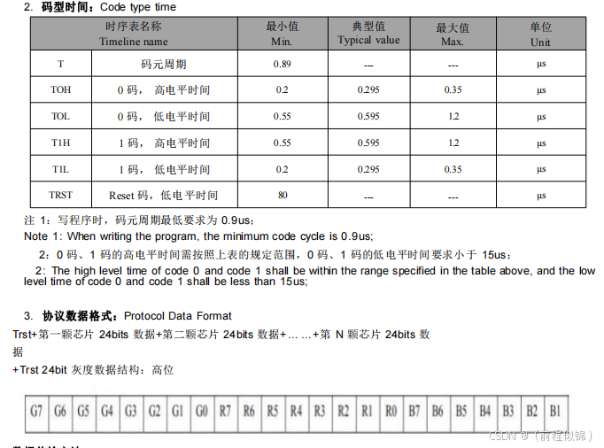
- C_NS(300) //表示 300 纳秒的时间常数,用于控制信号的时序。(0 码,高电平时间 和 1 码,低电平时间)
- C_NS(900) // 0 码,低电平时间 和 1 码,高电平时间
- C_NS(300) // Reset 码,低电平时间
- RGB_ORDER //RGB通道选择
//这个是自带的
template <uint8_t DATA_PIN, EOrder RGB_ORDER = RGB>
class SM16703Controller : public ClocklessController<DATA_PIN, C_NS(300), C_NS(600), C_NS(300), RGB_ORDER> {};
//下面这个是自己添加的
template <uint8_t DATA_PIN, EOrder RGB_ORDER = RGB>
class SM16705Controller : public ClocklessController80Bit<DATA_PIN, C_NS(300), C_NS(900), C_NS(300), RGB_ORDER> {};
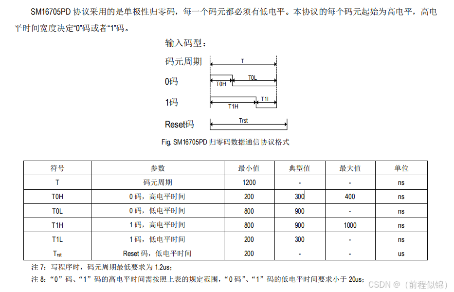
SM16705时序图:
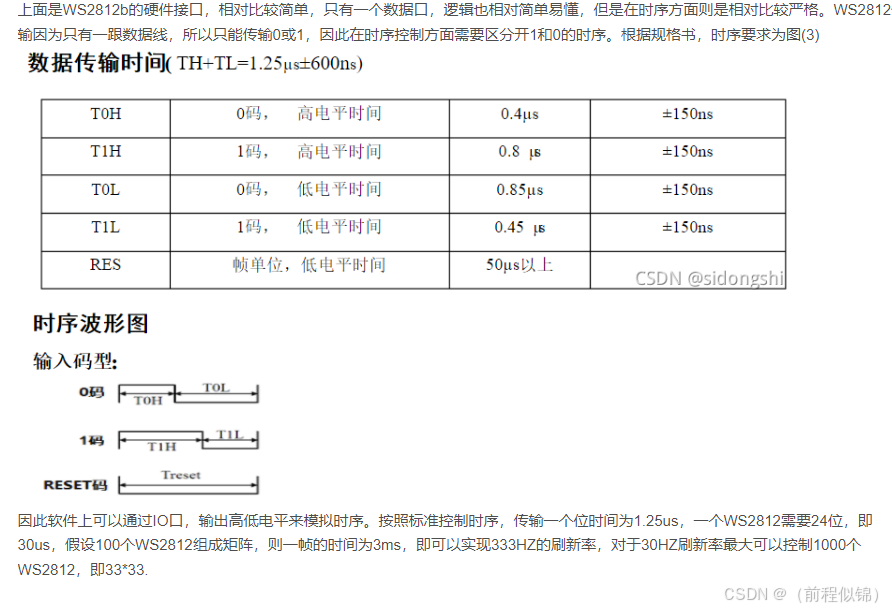
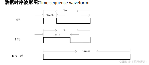
SW2812时序图(作为参考):
6. 在 FastLED.h 文件内添加芯片模板
- 有了这个才可以在 FastLED.addLeds() 这里面调用它,否则无法使用
/// @copydetails SM16703Controller //自己定义添加的
template<uint8_t DATA_PIN, EOrder RGB_ORDER>
class SM16705 : public SM16705Controller<DATA_PIN, RGB_ORDER> {};
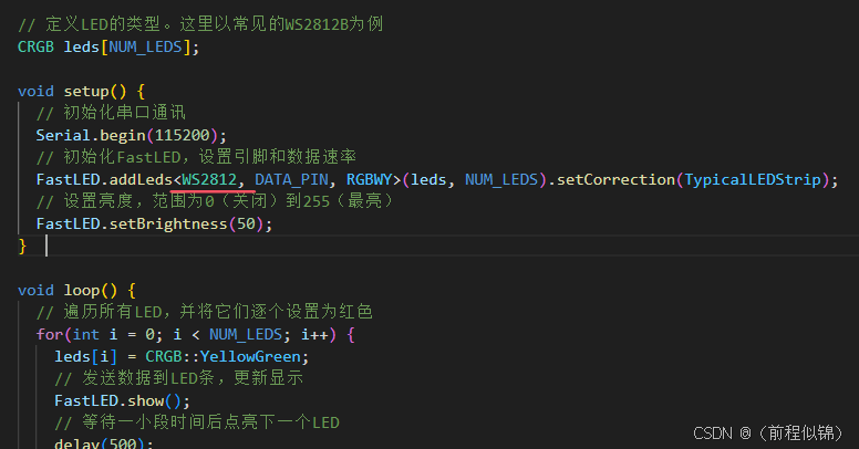
- 调用
// 初始化FastLED,设置引脚和数据速率
  FastLED.addLeds<SM16705, DATA_PIN, RGBWY>(leds, NUM_LEDS).setCorrection(TypicalLEDStrip);
  // 设置亮度,范围为0(关闭)到255(最亮)
  FastLED.setBrightness(50);
五、测试LED
下面给出个测试代码:下面的代码效果会按顺序点亮LED灯,并切换颜色。
#include "FastLED.h"
// 定义LED的数量和连接的引脚
#define NUM_LEDS 12
#define DATA_PIN 12

// 定义LED的类型。这里以常见的WS2812B为例
CRGB leds[NUM_LEDS];
void setup() {
  // 初始化串口通讯
  Serial.begin(115200);
  // 初始化FastLED,设置引脚和数据速率
  FastLED.addLeds<SM16705, DATA_PIN, RGBWY>(leds, NUM_LEDS).setCorrection(TypicalLEDStrip);
  // 设置亮度,范围为0(关闭)到255(最亮)
  FastLED.setBrightness(50);
}
void loop() {
  // 遍历所有LED,并将它们逐个设置为红色
  for(int i = 0; i < NUM_LEDS; i++) {
    leds[i] = CRGB::YellowGreen;
    // 发送数据到LED条,更新显示
    FastLED.show();
    // 等待一小段时间后点亮下一个LED
    delay(500);
  }
  // 等待一小段时间后再次更新
  delay(1000);

  // 遍历所有LED,并将它们逐个设置为蓝色
  for(int i = 0; i < NUM_LEDS; i++) {
    leds[i] = CRGB::Green;
    // 发送数据到LED条,更新显示
    FastLED.show();
    // 等待一小段时间后点亮下一个LED
    delay(500);
  }
  // 等待一小段时间后再次更新
  delay(1000);
}
六、添加芯片小结问题
1. 为什么会要在添加 ClocklessControllerBase 添加派生类
- 因为 FastLED库只支持 24bit 的颜色设置,一般 ws2812 芯片 只需要 3 个字节的数据来表示颜色 分别为 R \ G \ B 三种每一种占一个字节,一个字节就是 8bit 数据,3个字节就是 24bit 数据
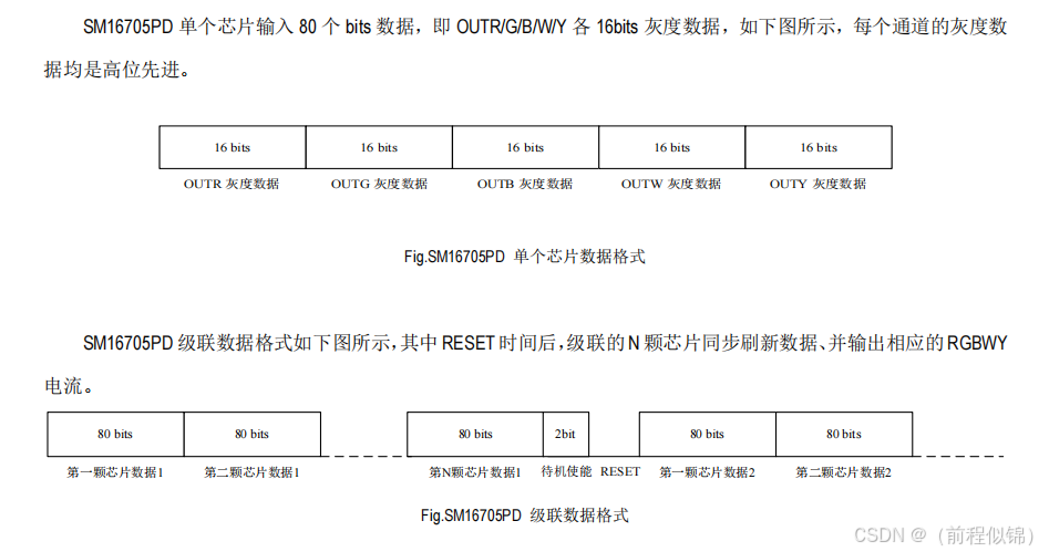
- SM16705PD 支持 5 种颜色(或5个通道),每种颜色需要 16 个bit表示(2个字节),因此总共有 80bit 的数据,因此才需要派生出一个类来专门处理 80bit 的数据
- 下面是 WS2812与SM16705PD对比图:
SM16705PD数据格式图:
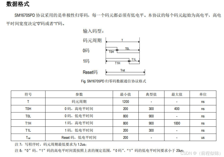
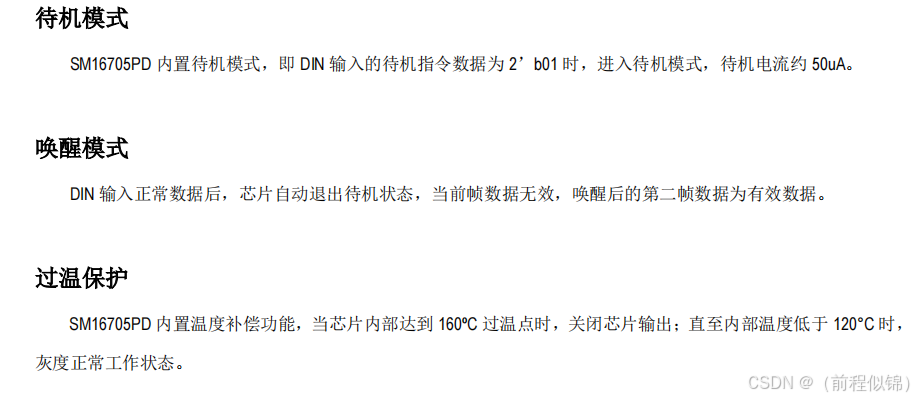
SM16705PD数据模式图:
WS2812数据时序图:
2. pixels.loadAndScale0() 的作用:
观察代码 :
uint8_t r = pixels.loadAndScale0();
uint8_t g = pixels.loadAndScale1();
uint8_t b = pixels.loadAndScale2();
- 这里面每个代码的返回值就是一个 字节的颜色数据,因此这里会有3个字节的数据返回出来
- 而我们添加 loadAndScale4() 和 loadAndScale5() 的作用就是让数据在返回两个通道的值,会分别给 W 和 Y ,就是白色和黄色,这样我们才能凑齐 5 个通道的值
- 但是 因为 loadAndScale()本身就只返回一个字节的数据,而我们的 SM16705需要2和字节的数据,因此我们才需要下面这样做(这样就可以凑齐80bit的数据了):
// 将8位颜色数据扩展为16位
            *pData++ = r; // 高8位
            *pData++ = r; // 低8位
            *pData++ = g; // 高8位
            *pData++ = g; // 低8位
            *pData++ = b; // 高8位
            *pData++ = b; // 低8位
            *pData++ = w; // 高8位
            *pData++ = w; // 低8位
            *pData++ = y; // 高8位
            *pData++ = y; // 低8位
3. 模板解释:
//父类
template <int DATA_PIN, int T1, int T2, int T3, EOrder RGB_ORDER = RGB, int XTRA0 = 0, bool FLIP = false, int WAIT_TIME = 5>
class ClocklessController80Bit : public ClocklessControllerBase<DATA_PIN, T1, T2, T3, RGB_ORDER, XTRA0, FLIP, WAIT_TIME>
//派生类
template <uint8_t DATA_PIN, EOrder RGB_ORDER = RGB>
class SM16705Controller : public ClocklessController80Bit<DATA_PIN, C_NS(300), C_NS(900), C_NS(300), RGB_ORDER> {};
参数解释:
ClocklessController80Bit 类是一个模板类,继承自 ClocklessControllerBase 类。该类用于控制无时钟信号的 LED 灯带,通常用于 ESP32 平台。
模板参数:
DATA_PIN:数据引脚,用于控制 LED 灯带。
T1:第一个时间常数,单位为纳秒。(0 码,高电平时间;1 码,低电平时间)
T2:第二个时间常数,单位为纳秒。(0 码,低电平时间;1 码,高电平时间)
T3:第三个时间常数,单位为纳秒。(Reset 码,低电平时间)
RGB_ORDER:颜色顺序,默认为 RGB。
XTRA0:额外参数,默认为 0。
FLIP:布尔值,指示是否翻转信号,默认为 false。
WAIT_TIME:等待时间,单位为微秒,默认为 5。
4. 如果不想修改库,也可以使用以下代码:
#include "Arduino.h"
#include "esp32-hal.h"

// 根据不同的 ESP32 目标板定义内置 RGB LED 引脚
#define BUILTIN_RGBLED_PIN   12   // ESP32 没有内置 RGB LED

// 定义 LED 数量和总位数
#define NR_OF_LEDS   12  // LED 数量
#define NR_OF_ALL_BITS 80*NR_OF_LEDS  // 每个 LED 80 bits

// 定义 RMT 数据数组
rmt_data_t led_data[NR_OF_ALL_BITS + 2];  // 额外的 2 bits 用于待机指令

// 定义 RMT 发送对象指针
rmt_obj_t* rmt_send = NULL;

void setup()
{
    Serial.begin(115200);  // 初始化串口通信,波特率为 115200

    // 初始化 RMT 发送对象
    if ((rmt_send = rmtInit(BUILTIN_RGBLED_PIN, RMT_TX_MODE, RMT_MEM_64)) == NULL)
    {
        Serial.println("init sender failed\n");  // 如果初始化失败,打印错误信息
    }

    // 设置 RMT 时钟周期
    float realTick = rmtSetTick(rmt_send, 100);  // 设置 RMT 时钟周期为 100ns
    Serial.printf("real tick set to: %fns\n", realTick);  // 打印实际设置的时钟周期
}

// 定义 RGB 颜色值
uint16_t color[] =   { 0x0000, 0x0000, 0x0000, 0x0000, 0xFFFF };  // 仅黄色通道有值,其他通道为 0
int led_index = 0;  // 当前点亮的 LED 索引

void loop()
{
    // 初始化数据,仅点亮一个 LED
    int led, col, bit;
    int i = 0;
    for (led = 0; led < NR_OF_LEDS; led++) {
        for (col = 0; col < 5; col++) {
            for (bit = 0; bit < 16; bit++) {
                if ((color[col] & (1 << (15 - bit))) && (led == led_index)) {
                    // 设置 RMT 数据项表示逻辑 1
                    led_data[i].level0 = 1;  // 第一个阶段为高电平
                    led_data[i].duration0 = 9;  // 第一个阶段持续 900ns
                    led_data[i].level1 = 0;  // 第二个阶段为低电平
                    led_data[i].duration1 = 3;  // 第二个阶段持续 300ns
                } else {
                    // 设置 RMT 数据项表示逻辑 0
                    led_data[i].level0 = 1;  // 第一个阶段为高电平
                    led_data[i].duration0 = 3;  // 第一个阶段持续 300ns
                    led_data[i].level1 = 0;  // 第二个阶段为低电平
                    led_data[i].duration1 = 9;  // 第二个阶段持续 900ns
                }
                i++;  // 增加 RMT 数据数组的索引
            }
        }
    }

    // 添加待机指令 2'b01
    // led_data[i].level0 = 1;  // 第一个阶段为高电平
    // led_data[i].duration0 = 3;  // 第一个阶段持续 300ns
    // led_data[i].level1 = 0;  // 第二个阶段为低电平
    // led_data[i].duration1 = 9;  // 第二个阶段持续 900ns
    // i++;
    // led_data[i].level0 = 1;  // 第一个阶段为高电平
    // led_data[i].duration0 = 9;  // 第一个阶段持续 900ns
    // led_data[i].level1 = 0;  // 第二个阶段为低电平
    // led_data[i].duration1 = 3;  // 第二个阶段持续 300ns
    // i++;

    // 使 LED 在面板上移动
    if ((++led_index) >= NR_OF_LEDS) {
        led_index = 0;  // 如果超过 LED 数量,则重置为 0
    }

    // 发送数据
    rmtWrite(rmt_send, led_data, NR_OF_ALL_BITS + 2);  // 使用 RMT 发送 LED 数据

    // 进入待机模式后,进行 RESET
    delay(100);  // 延迟 100 毫秒
    rmtWrite(rmt_send, NULL, 0);  // 发送空数据以触发 RESET
    delay(200);  // 延迟 200 微秒以确保 RESET 完成
}
5. 修改定位顺序:
WS2812 定位:WS2812 -> WS2812Controller800Khz(父类) -> ClocklessController(父类)-> loadAndScale0()
LED通道定位顺序: RGB -> EOrder
增加通道上限: controller.h -> RGB_BYTE(RO,X)


 被折叠的 条评论
为什么被折叠?
被折叠的 条评论
为什么被折叠?
 到【灌水乐园】发言


