


路由
实验步骤:
第一步:IP地址规划
PC1:192.168.1.2 24 网关:192.168.1.1 24
PC2:192.168.2.2 24 网关:192.168.2.1 24
PC3:192.168.3.2 24 网关:192.168.3.1 24
PC4:192.168.4.2 24 网关:192.168.4.1 24
PC5:192.168.5.2 24 网关:192.168.5.1 24
R1-R4:R1 g0/0/1:16.1.1.1 24 R4 g2/0/0:16.1.1.2 24
R1 g0/0/2: 61.1.1.1 24 R4 g0/0/0:61.1.1.2 24
R2-R4: R2:24.1.1.1 24 R4:24.1.1.2 24
R3-R4: R3:34.1.1.1 24 R4:34.1.1.2 24
R5-R4: R5:54.1.1.1 24 R4:54.1.1.2 24
R6-R4: R6:64.1.1.1 24 R4:64.1.1.2 24
R4环回:4.4.4.4 24
第二步:IP地址配置
R1:
[R1]int g0/0/0
[R1-GigabitEthernet0/0/0]ip add 192.168.1.1 24
[R1]int g0/0/1
[R1-GigabitEthernet0/0/1]ip add 14.1.1.1 24
[R1]int g0/0/2
[R1-GigabitEthernet0/0/2]ip add 41.1.1.1 24
R2:
[R2]int g0/0/0
[R2-GigabitEthernet0/0/0]ip add 192.168.2.1 24
[R2]int g0/0/1
[R2-GigabitEthernet0/0/1]ip add 24.1.1.1 24
R3:
[R3]int g0/0/0
[R3-GigabitEthernet0/0/0]ip add 192.168.3.1 24
[R3]int g0/0/1
[R3-GigabitEthernet0/0/1]ip add 34.1.1.1 24
R4:
[R4]int g0/0/0
[R4-GigabitEthernet0/0/0]ip add 41.1.1.2 24
[R4]int g2/0/0
[R4-GigabitEthernet2/0/0]ip add 14.1.1.2 24
[R4]int g0/0/1
[R4-GigabitEthernet0/0/1]ip add 24.1.1.2 24
[R4]int g0/0/2
[R4-GigabitEthernet0/0/2]ip add 34.1.1.2 24
[R4]int g3/0/0
[R4-GigabitEthernet3/0/0]ip add 54.1.1.2 24
[R4]int g4/0/0
[R4-GigabitEthernet4/0/0]ip add 64.1.1.2 24
[R4]int LoopBack 0
[R4-LoopBack0]ip add 4.4.4.4 24
R5:
[R5]int g0/0/0
[R5-GigabitEthernet0/0/0]ip add 192.168.4.1 24
[R5]int g0/0/1
[R5-GigabitEthernet0/0/1]ip add 54.1.1.1 24
R6:
[R6]int g0/0/0
[R6-GigabitEthernet0/0/0]ip add 192.168.5.1 24
[R6]int g0/0/1
[R6-GigabitEthernet0/0/1]ip add 64.1.1.1 24
第三步:配置缺省路由
[R1]ip route-static 0.0.0.0 0 14.1.1.2
[R1]ip route-static 0.0.0.0 0 41.1.1.2
[R2]ip route-static 0.0.0.0 0 24.1.1.2
[R3]ip route-static 0.0.0.0 0 34.1.1.2
[R5]ip route-static 0.0.0.0 0 54.1.1.2
[R6]ip route-static 0.0.0.0 0 64.1.1.2
第四步:NAT
R1:
[R1]acl 2000
[R1-acl-basic-2000]rule 1 permit source any
[R1]int g0/0/1
[R1-GigabitEthernet0/0/1]nat outbound 2000
[R1]int g0/0/2
[R1-GigabitEthernet0/0/2]nat outbound 2000
R2:
[R2]acl 2000
[R2-acl-basic-2000]rule 1 permit source any
[R2]int g0/0/1
[R2-GigabitEthernet0/0/1]nat outbound 2000
R3、R5、R6同理。
第五步:R1-2-3 构建一个星型结构的MGRE结构,其中R1为中心点
注意:需要开启伪广播
R1:
[R1]interface Tunnel 0/0/0
[R1-Tunnel0/0/0]tunnel-protocol gre p2mp
[R1-Tunnel0/0/0]ip add 10.1.1.1 24
[R1-Tunnel0/0/0]source 41.1.1.1
[R1-Tunnel0/0/0]nhrp network-id 100
[R1-Tunnel0/0/0]nhrp entry multicast dynamic
R2:
[R2]interface Tunnel 0/0/0
[R2-Tunnel0/0/0]tunnel-protocol gre p2mp
[R2-Tunnel0/0/0]ip add 10.1.1.2 24
[R2-Tunnel0/0/0]source g0/0/1
[R2-Tunnel0/0/0]nhrp network-id 100
[R2-Tunnel0/0/0]nhrp entry 10.1.1.1 41.1.1.1 register
R3:
[R3]interface Tunnel 0/0/0
[R3-Tunnel0/0/0]tunnel-protocol gre p2mp
[R3-Tunnel0/0/0]ip add 10.1.1.3 24
[R3-Tunnel0/0/0]source g0/0/1
[R3-Tunnel0/0/0]nhrp network-id 100
[R3-Tunnel0/0/0]nhrp entry 10.1.1.1 41.1.1.1 register
第六步:R1-5-6 构建另一个全连网状的MGRE网络,其中R1/5均中心区域
注意:需要开启伪广播
R1:
[R1]interface Tunnel 0/0/1
[R1-Tunnel0/0/1]tunnel-protocol gre p2mp
[R1-Tunnel0/0/1]ip add 20.1.1.1 24
[R1-Tunnel0/0/1]source 14.1.1.1
[R1-Tunnel0/0/1]nhrp network-id 101
[R1-Tunnel0/0/1]nhrp entry 20.1.1.2 54.1.1.1 register
[R1-Tunnel0/0/1]nhrp entry multicast dynamic
R5:
[R5]interface Tunnel 0/0/1
[R5-Tunnel0/0/1]tunnel-protocol gre p2mp
[R5-Tunnel0/0/1]ip add 20.1.1.2 24
[R5-Tunnel0/0/1]source 54.1.1.1
[R5-Tunnel0/0/1]nhrp network-id 101
[R5-Tunnel0/0/1]nhrp entry 20.1.1.1 14.1.1.1 register
[R5-Tunnel0/0/1]nhrp entry multicast dynamic
R6:
[R6]interface Tunnel 0/0/1
[R6-Tunnel0/0/1]tunnel-protocol gre p2mp
[R6-Tunnel0/0/1]ip add 20.1.1.3 24
[R6-Tunnel0/0/1]source g0/0/1
[R6-Tunnel0/0/1]nhrp network-id 101
[R6-Tunnel0/0/1]nhrp entry 20.1.1.1 14.1.1.1 register
[R6-Tunnel0/0/1]nhrp entry 20.1.1.2 54.1.1.1 register
第七步:OSPF路由配置
R1:
[R1]ospf 1 router-id 1.1.1.1
[R1-ospf-1]area 0
[R1-ospf-1-area-0.0.0.0]network 192.168.1.0 0.0.0.255
[R1-ospf-1-area-0.0.0.0]network 10.1.1.0 0.0.0.255
[R1-ospf-1-area-0.0.0.0]network 20.1.1.0 0.0.0.255
R2:
[R2]ospf 1 router-id 2.2.2.2
[R2-ospf-1]area 0
[R2-ospf-1-area-0.0.0.0]network 192.168.2.0 0.0.0.255
[R2-ospf-1-area-0.0.0.0]network 10.1.1.0 0.0.0.255
R3:
[R3]ospf 1 router-id 3.3.3.3
[R3-ospf-1]area 0
[R3-ospf-1-area-0.0.0.0]network 192.168.3.0 0.0.0.255
[R3-ospf-1-area-0.0.0.0]network 10.1.1.0 0.0.0.255
R5:
[R5]ospf 1 router-id 5.5.5.5
[R5-ospf-1]area 0
[R5-ospf-1-area-0.0.0.0]network 192.168.4.0 0.0.0.255
[R5-ospf-1-area-0.0.0.0]network 20.1.1.0 0.0.0.255
R6:
[R6]ospf 1 router-id 6.6.6.6
[R6-ospf-1]area 0
[R6-ospf-1-area-0.0.0.0]network 192.168.5.0 0.0.0.255
[R6-ospf-1-area-0.0.0.0]network 20.1.1.0 0.0.0.255
在MGRE环境中,接口默认的ospf工作方式为点到点,这种方式无法实现该NBMA网段的邻居全连;故只能去修改接口的工作方式
修改接口的工作方式:
[R1-Tunnel0/0/0]ospf network-type broadcast
[R1-Tunnel0/0/1]ospf network-type broadcast
[R2-Tunnel0/0/0]ospf network-type broadcast
[R3-Tunnel0/0/0]ospf network-type broadcast
[R5-Tunnel0/0/1]ospf network-type broadcast
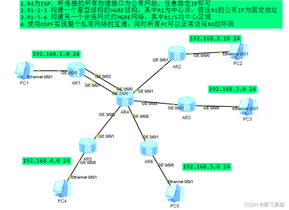
[R6-Tunnel0/0/1]ospf network-type broadcast 现在可以看见R1与其他路由器都是邻接关系
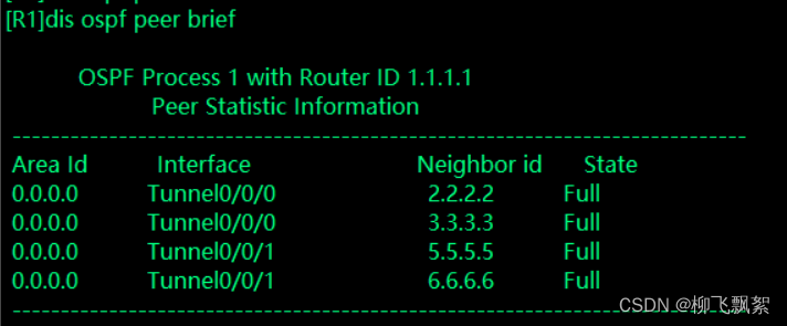
但是没有R2的ospf路由
需要修改R2和R3的优先级:
[R2]interface Tunnel 0/0/0
[R2-Tunnel0/0/0]ospf dr-priority 0
[R3]interface Tunnel 0/0/0
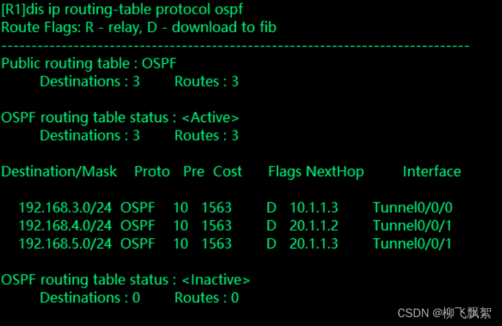
[R3-Tunnel0/0/0]ospf dr-priority 0现在R1上有所有的ospf路由了
测试:
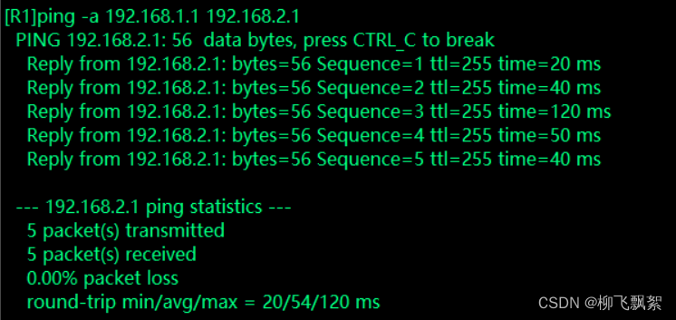
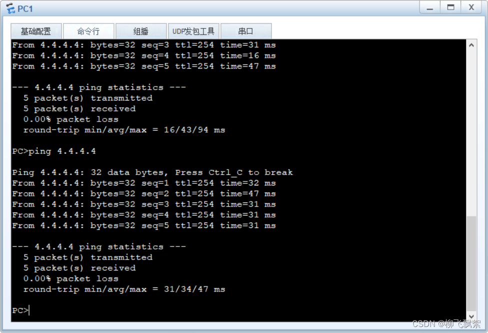


 7294
7294

 被折叠的 条评论
为什么被折叠?
被折叠的 条评论
为什么被折叠?
 到【灌水乐园】发言


