 静态路由综合实验步骤与实现


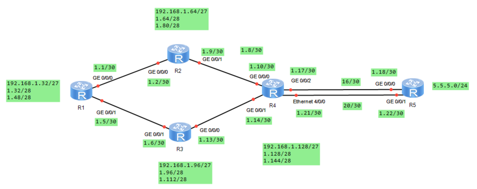
一、实验拓扑
二、实验要求
1.除了R5的环回地址固定5.5.5.0/24,其他网段基于192.168.1.0/24进行合理划分;
2.R1-R4每个路由器存在两个环回接口,模拟PC,地址也在192.168.1.0/24网络内;
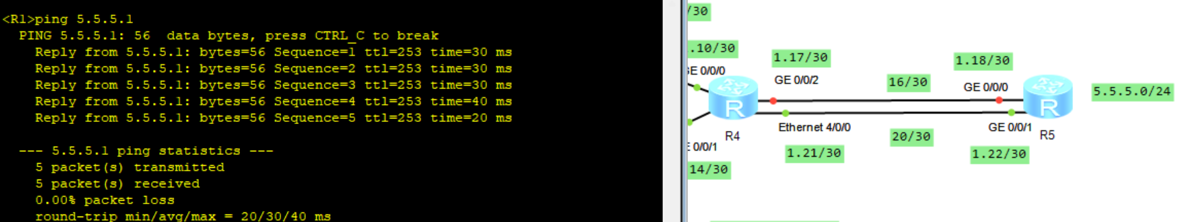
3.R1-R4不能直接编写到达5.5.5.0/24的静态路由,但依然可以访问;
4.全网可达,尽量减少每台路由器路由条目数量,避免环路;
5.R4与R5间,正常1000M链路通信,故障时自动改为100M;
三、实验步骤
步骤一:
划分网段,根据要求和拓扑图,共有15个广播域,可分为骨干链路与各环回。
先将192.168.1.0/24划分5个网段,由2^3=8,子网掩码/27---255.255.255.224。
(1)192.168.1.0000 0000----192.168.1.0/27----骨干链路
再将该网段细化分出六个网段:
192.168.1.0000 0000--192.168.1.0/30---255.255.255.252
192.168.1.0000 0100--192.168.1.4/30
192.168.1.0000 1000--192.168.1.8/30
192.168.1.0000 1100--192.168.1.12/30
192.168.1.0001 0000--192.168.1.16/30
192.168.1.0001 0100--192.168.1.20/30
各环回也得一个大网段后再细化成两个网段:
(2)192.168.1.0010 0000----192.168.1.32/27----R1环回
192.168.1.0010 0000---192.168.1.32/28
192.168.1.0011 0000---192.168.1.48/28
(3)192.168.1.0100 0000----192.168.1.64/27---R2环回
192.168.1.0100 0000---192.168.1.64/28
192.168.1.0101 0000---192.168.1.80/28
(4)192.168.1.0110 0000----192.168.1.96/27--R3环回
192.168.1.0110 0000---192.168.1.96/28
192.168.1.0111 0000--192.168.1.112/28
(5)192.168.1.1000 0000----192.168.1.128/27--R4环回
192.168.1.1000 0000---192.168.1.128/28
192.168.1.1001 0000--192.168.1.144/28
步骤二:
进入路由设备的用户视图,改名字后,配置IP地址。以R1为例:
<Huawei> system-view
[Huawei] sysname R1环回配置
[R1] interface LoopBack 1
[R1-LoopBack0] ip address 192.168.1.33 28
[R1-LoopBack0] quit
[R1] interface LoopBack 2
[R1-LoopBack1] ip address 192.168.1.49 28
[R1-LoopBack1] quit接口配置
[R1]int g0/0/0
[R1-GigabitEthernet0/0/0]ip address 192.168.1.1 30
[R1-GigabitEthernet0/0/0]q
[R1]int g0/0/1
[R1-GigabitEthernet0/0/1]ip address 192.168.1.5 30
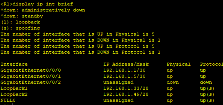
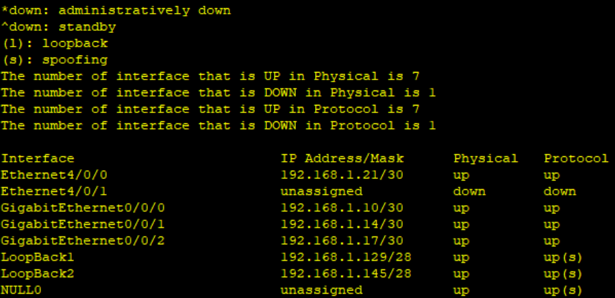
R1接口信息
[R1]display ip int brief
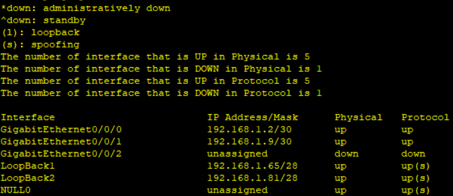
R2
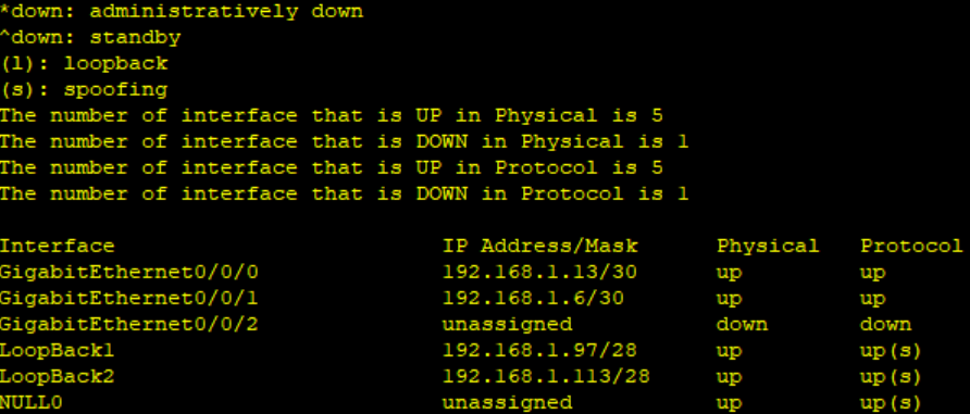
R3
R4
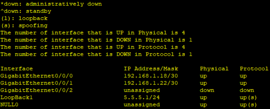
R5
步骤三:
配置静态路由信息,除直连路由及5.5.5.0/24网段外全部用静态路由写入网段信息。
格式:
ip route-static 192.168.1. 8 30 192.168.1.2
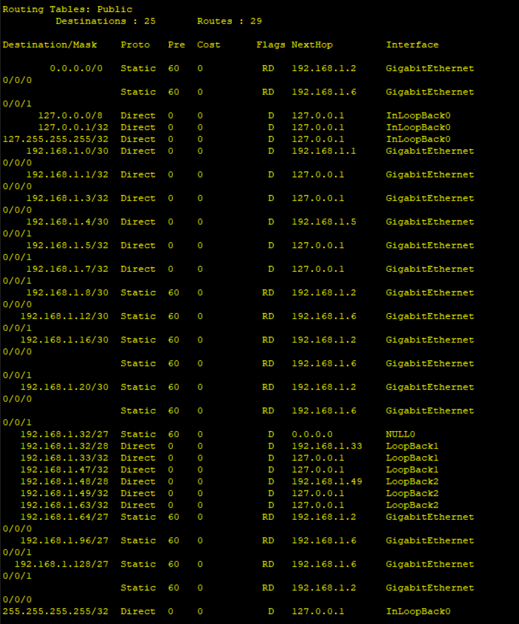
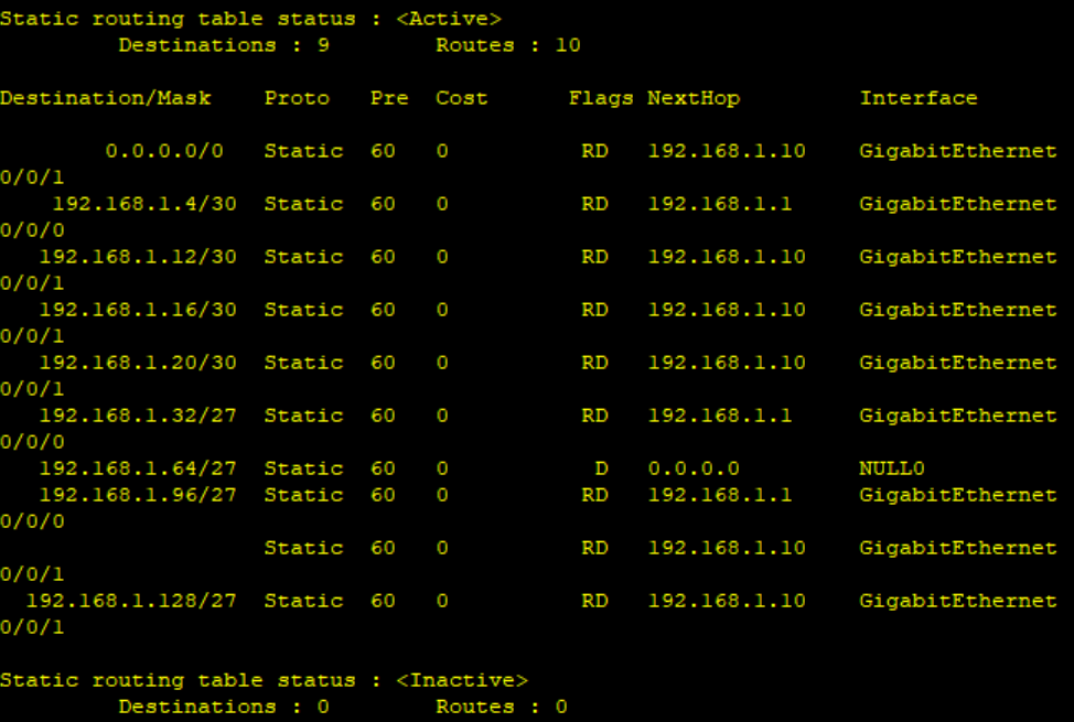
查看本设备路由表信息:
[R1]display ip routing-table
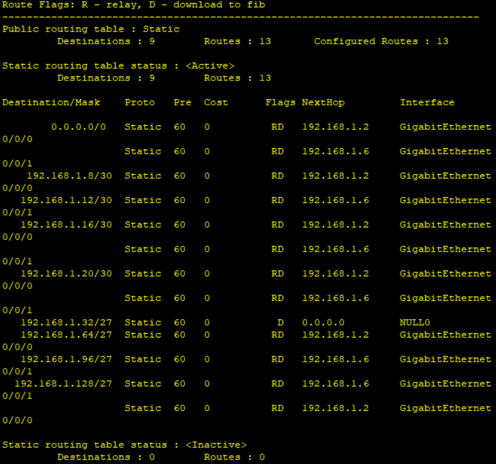
display ip routing-table protocol static
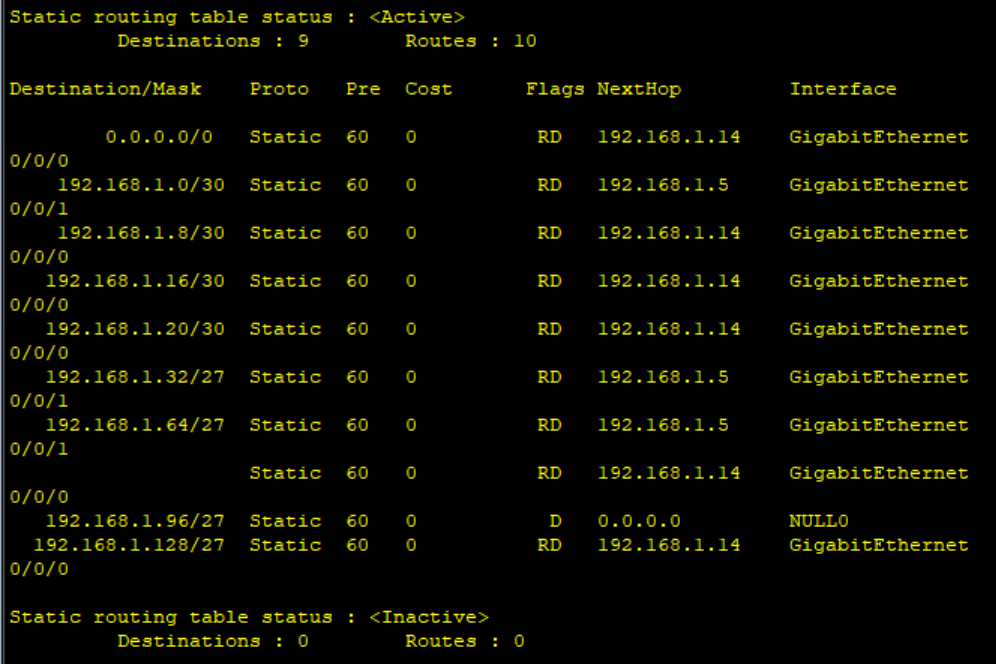
R2
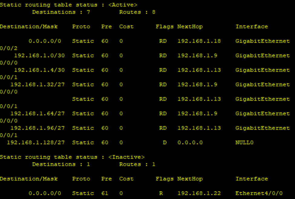
R3
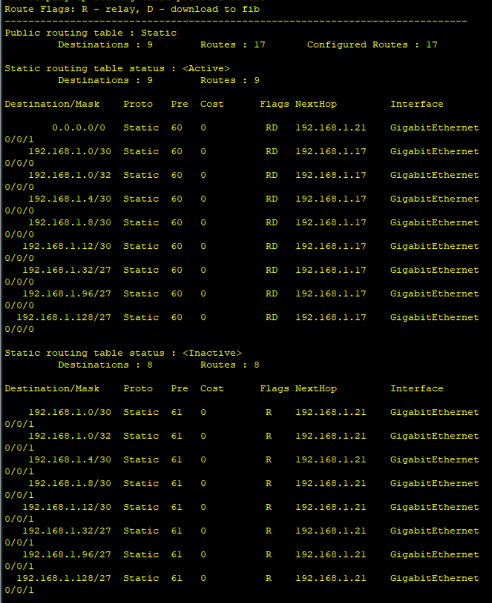
R4
R5
步骤四:R1-R4不能直接编写到达5.5.5.0/24的静态路由,但依然可以访问;
给R1-R4配置缺省路由:
[R1]ip route-static 0.0.0.0 0 192.168.1.2
[R1]ip route-static 0.0.0.0 0 192.168.1.6
[R2]ip route-static 0.0.0.0 0 192.168.1.10
[R3]ip route-static 0.0.0.0 0 192.168.1.14
[R4]ip route-static 0.0.0.0 0 192.168.1.18
[R4]ip route-static 0.0.0.0 0 192.168.1.22
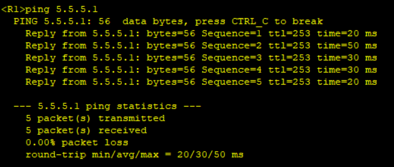
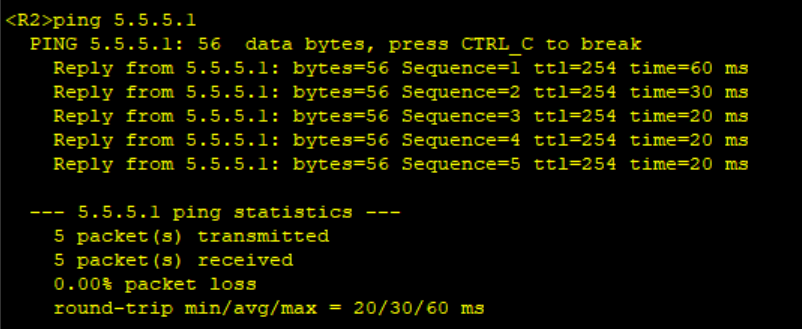
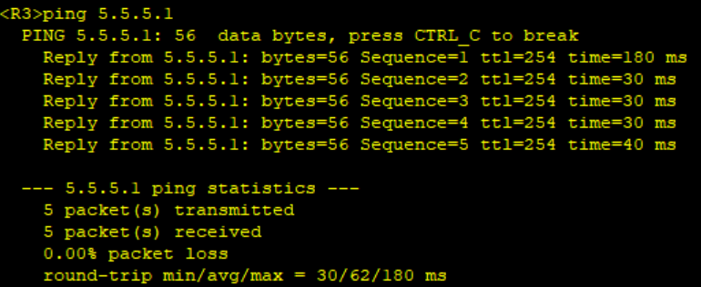
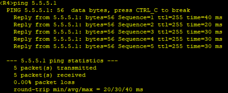
检验:
步骤五:全网可达,尽量减少每台路由器路由条目数量,避免环路;
[R1] ip route-static 192.168.1.32 27 null0
[R2] ip route-static 192.168.1.64 27 null0
[R3] ip route-static 192.168.1.96 27 null0
[R4] ip route-static 192.168.1.128 27 null0
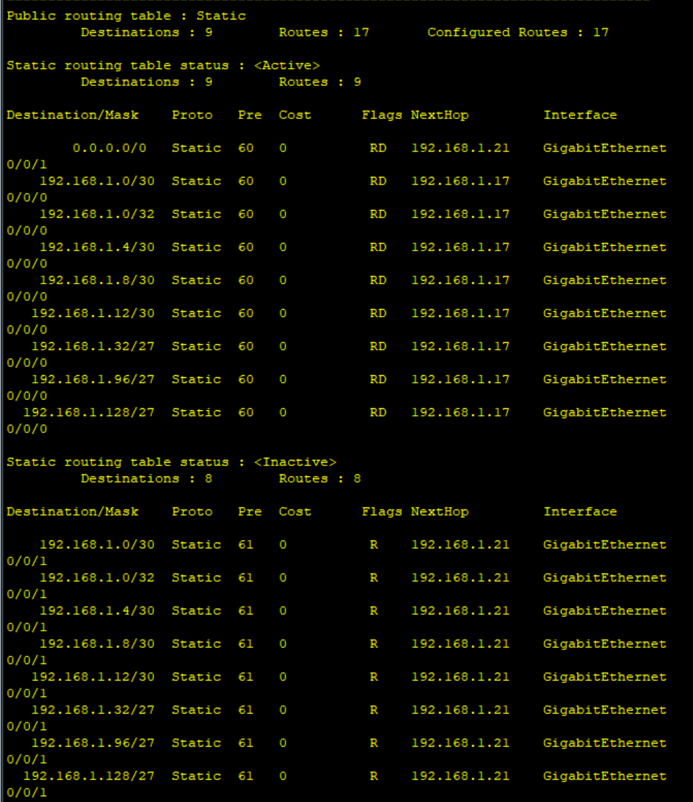
步骤六:R4与R5间,正常1000M链路通信,故障时自动改为100M;
Eg:
[R4]ip route-static 0.0.0.0 0 192.168.1.22 preference 61
修改后R5:
检验,shutdown R4的g0/0/2 接口,依旧可以通信:
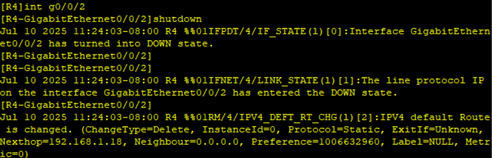
实验完成。


 3168
3168

 被折叠的 条评论
为什么被折叠?
被折叠的 条评论
为什么被折叠?
 到【灌水乐园】发言


