


 本文介绍了一种使用STM32官方固件库的方法,通过配置GPIO端口来实现机械按键控制RGB LED灯的开关。硬件中,KEY1连接到PA0,KEY2连接到PC13,RGB LED的红、绿、蓝分别连接到PB5、PB0和PB1。主要涉及的代码文件包括bsd_led.h和.c,bsd_key.h和.c以及main.c。
- 利用官方固件库开发
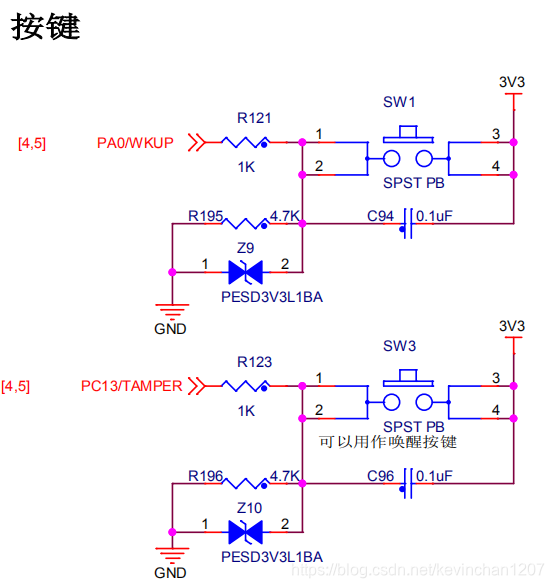
1.硬件说明
机械按键:KEY1-> PA0; KEY2->PC13
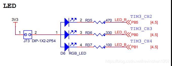
RGB LED:R-> PB5; G->PB0; B->PB1
2.bsd_led.h
//为了防止被多个文件调用的时候出现重复定义的错误,我们需要用#ifndef 。。。#endif
#ifndef _BSP_LED_H
#define _BSP_LED_H

#include "stm32f10x.h"

#define LED_R_GPIO_PIN	GPIO_Pin_5
#define LED_G_GPIO_PIN	GPIO_Pin_0
#define LED_B_GPIO_PIN	GPIO_Pin_1
#define LED_RGB_GPIO_PORT	GPIOB
#define LED_RGB_GPIO_CLK	RCC_APB2Periph_GPIOB

#define ON 0
#define OFF 1

#define LED_G(a) if(a) GPIO_SetBits(LED_G_GPIO_PORT, LED_G_GPIO_PIN);else GPIO_ResetBits(LED_G_GPIO_PORT, LED_G_GPIO_PIN);
//^异或
//与1异或改变为0,与0异或不变还是0
#define LED_G_TOGGLE {LED_RGB_GPIO_PORT->ODR ^= LED_G_GPIO_PIN;}
#define LED_R_TOGGLE {LED_RGB_GPIO_PORT->ODR ^= LED_R_GPIO_PIN;}

void led_init(void);

#endif /* _BSP_LED_H */
3.bsd_led.c
#include "bsp_led.h"

void led_init(void)
{
	//新建初始化结构体
	GPIO_InitTypeDef GPIO_InintStruct;

	//打开GPIOB->RCC端口的时钟,PB0和PB5相同端口,
	RCC_APB2PeriphClockCmd(LED_RGB_GPIO_CLK, ENABLE);

	//定义IO口引脚PB0
	GPIO_InintStruct.GPIO_Pin = LED_G_GPIO_PIN;
	//配置IO口GPIOB->CRL为推挽输出模式
	GPIO_InintStruct.GPIO_Mode = GPIO_Mode_Out_PP;
	//配置IO口GPIOB->CRL为输出速度
	GPIO_InintStruct.GPIO_Speed = GPIO_Speed_50MHz;
		//初始化
	GPIO_Init(LED_RGB_GPIO_PORT, &GPIO_InintStruct);

	//定义IO口引脚PB5
	GPIO_InintStruct.GPIO_Pin = LED_R_GPIO_PIN;
	//初始化
	GPIO_Init(LED_RGB_GPIO_PORT, &GPIO_InintStruct);
}
4.bsd_key.h
#ifndef _BSP_KEY1_H
#define _BSP_KEY1_H

#include "stm32f10x.h"

#define KEY1_GPIO_PIN	GPIO_Pin_0  //定义LED引脚
#define KEY1_GPIO_PORT	GPIOA
#define KEY1_GPIO_CLK	RCC_APB2Periph_GPIOA

#define KEY2_GPIO_PIN	GPIO_Pin_13  //定义LED引脚
#define KEY2_GPIO_PORT	GPIOC
#define KEY2_GPIO_CLK	RCC_APB2Periph_GPIOC

#define KEY_ON 1
#define KEY_OFF 0


void key_init(void);
uint8_t Key_Scan(GPIO_TypeDef *GPIOx,uint16_t GPIO_Pin);
#endif /* _BSP_KEY1_H */
5.bsd_key.c
#include "bsp_key.h"

void key_init(void)
{
		//新建初始化结构体
	GPIO_InitTypeDef GPIO_InintStruct;

		//使能PA,PC端口时钟
	RCC_APB2PeriphClockCmd(KEY1_GPIO_CLK|KEY2_GPIO_CLK, ENABLE);

	GPIO_InintStruct.GPIO_Pin = KEY1_GPIO_PIN;
	GPIO_InintStruct.GPIO_Mode = GPIO_Mode_IN_FLOATING;
	GPIO_Init(KEY1_GPIO_PORT, &GPIO_InintStruct);

	GPIO_InintStruct.GPIO_Pin = KEY2_GPIO_PIN;
	GPIO_InintStruct.GPIO_Mode = GPIO_Mode_IN_FLOATING;
	GPIO_Init(KEY2_GPIO_PORT, &GPIO_InintStruct);

}


uint8_t Key_Scan(GPIO_TypeDef *GPIOx,uint16_t GPIO_Pin) //*GPIOx端口;GPIO_Pin引脚
{
	if (GPIO_ReadInputDataBit(GPIOx, GPIO_Pin) == KEY_ON)
	{
		while(GPIO_ReadInputDataBit(GPIOx, GPIO_Pin) == KEY_ON);
		return KEY_ON;
	}
	else return KEY_OFF;

}
6.main.c
/* Includes ------------------------------------------------------------------*/
#include "stm32f10x.h"
#include "bsp_led.h"
#include "bsp_key.h"

int main(void)
{
	led_init();
    key_init();

	while(1)
	{
		if(Key_Scan(KEY1_GPIO_PORT,KEY1_GPIO_PIN) == KEY_ON)
			LED_G_TOGGLE;
		if(Key_Scan(KEY2_GPIO_PORT,KEY2_GPIO_PIN) == KEY_ON)
			LED_R_TOGGLE;
	}
}


 5520
5520

 被折叠的 条评论
为什么被折叠?
被折叠的 条评论
为什么被折叠?
 到【灌水乐园】发言


